
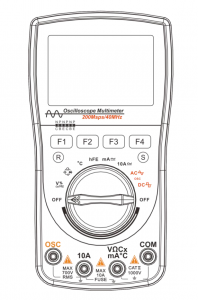
Oscilloscope Multimeter
Safety Instructions
This digital oscilloscope multi-meter is designed in conformity with safety specifications of IEC1010-1. Second category of overvoltage measurement: CAT III – 1000V; pollution protection level: Level 1.
- Before use, please check the housing first to see if it has any crack or any required plastic part is missing. Do not use instrument with broken housing. Special attention shall be paid to the insulating layer of test leads and connecting lines. When using test leads, do not touch the metal part of the probe of test leads with your finger;
- Do not operate the multimeter in high-temperature, moist, rainy, inflammable and explosive environment or when the instrument is wet;
- Never apply any voltage or current which exceeds the maximum limit of the instrument.
Measuring function
Input end used Maximum limit
V DC
V/
 ,COM
,COM1000V DC+AC peak value, within 10 seconds V AC
V/
,COM750V DC+AC virtual value, within 10 seconds Hz%
V/
,COM750V DC+AC virtual value, within 10 seconds mA AC/ DC
500mA,COM
500mA DC/AC virtual value, 250V/500mA fuse protective tube A AC/ DC
10A,COM
10A DC/AC virtual value, within 30 seconds. 15-minute interval for cooling. 250V/10A fuse protective tube V/
,COM250V DC/AC virtual value, within 10 seconds ℃
V/
,COM250V DC/AC virtual value, within 10 seconds hFE
V/
,COM250V DC/AC virtual value, within 10 seconds - When changing measuring function, please make sure the probe of test leads is taken away from the test point before plugging in/out the plug of test leads and before switching on/off the device.
- Pay attention to the safety warning signal displayed on the instrument: When the measured voltage exceeds the “safety voltage” (24VDC/AC), a warning information “ ”is displayed to remind you;
- When the voltage to earth on the reference end “COM” of the instrument reaches 500V, please do not make voltage measurement;
- Please do not make AC current measurement of circuits with a voltage of over AC 250V;
- When measuring functions are pointed at the gears of current, resistance, continuity test, diode, capacitance and ℃ etc., never bridge the test leads over the two ends of the probe of voltage;
- Before the test of resistance, diode/continuity test, the power of the equipment to be tested must be cut off and make sure the capacitor of the circuit has been fully discharged;
- Before opening the back cover of instrument for replacement of protective tube, the power of the instrument must be turned off and the test lead should be kept away from the circuit to be tested; protective tube of the same specification must be used for replacement;
- Do not alter or dismantle the product or its accessories or use them for purposes other than the purpose for which the product is designed. No accessory and attachment may be replaced casually
Safety signs
 |
Caution, danger! This sign appears near other signs or socket terminals to remind users that the instruction of the manual must be followed during operation, so as to prevent damage to the instrument/personal injury. |
 |
Caution, electricity shock! This sign appears near one or more terminals to indicate that there may be hazard voltage in the terminal(s) during use. To ensure utmost safety, please avoid touching the testing end of test leads when there is voltage in the terminal(s). |
|
Instruction! |
Instruction suggests that special attention should be paid during operation, as wrongful operation will result in incorrect measurement result or damage of accessories. |
|
Attention! |
Attention suggests that the operation must be done very carefully, as wrongful operation or violation may result in damage of the product or other property. |
|
Warning! |
Warning suggests that high concentration is required during operation, as wrongful operation or violation may result in personal injury or even endangering of life. |
Introduction to the Instrument
Main features
- 200Msps high-speed sampling, 40MHz analog bandwidth, 6000 digital multimeter
- Rotary knob for switching oscillography with three types of waveform scanning mode i.e. automatic mode, regular mode and single-time mode
- Save function for data and waveform in the measurement; a total of 100 sets of data and 50 waveform can be saved
- Parameters i.e. time base and waveform scanning mode can be set in measurement of waveform
- TRMS, measure the virtual value of waveform without taking into account the waveform parameter and distortion
- REL, effectively eliminate the lead resistance, distributed capacitance and interference signal
- The functions include DC/AC voltage/current, resistance, capacitance, frequency, temperature, diode/continuity test, triode
- Automatic/manual switching for measuring range and display of measurement data and historic data on the same screen
- Overload protection 500mA/10A double protective tube, dual protection of the instrument
- Automatic shutdown in case of no operations for 15 minutes: bright backlight and clear display
- higher reliability: no adjustment of potentiometer is required for panel calibration and internal storage calibration
|
BUTTONS |
Name |
Function |
|
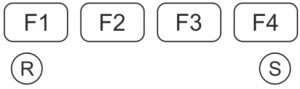
F1 ~ F4 |
The actual function varies with the measuring range and work mode. The option menu displayed on the LCD serves as the prompt for action. |
|
R |
Waveform capture button | |
|
S |
Data save button | |
 |
OFF |
Instrument switch |
 |
AC/DC Voltage/Frequency/Duty ratio | |
 |
Resistance/Diode/Continuity test/ Capacitance | |
|
℃ |
Temperature | |
|
hFE |
Triode | |
|
mA |
AC/DC mA | |
|
10A |
AC/DC 10A | |
| AC waveform | ||
| DC waveform |
Basic operation
Start-up and shutdown
Rotate the rotary knob to desired measurement gear and the power is connected to the instrument; rotate the rotary knob to OFF position to turn off the power
|
Attention! |
|
Automatic sleep
If there is no operation for a set period of time, the instrument will get into automatic sleep. To turn off the function of automatic sleep, user may press the “R” button and then rotate the rotary knob to turn on the instrument. In this way, the instrument is set to continuous working mode. To prevent over discharge of battery inside the instrument, the instrument may also get into automatic sleep when the electricity of batter is about to be exhausted.After the function of automatic close is initiated, a sleep symbol of “ ” will be displayed less than 1 minute before the instrument gets into sleep mode.
Operations of the scopemeter
Entering into the scopemeter mode
Rotate the rotary knob to select the scopemeter (OSC) mode
|
Instructions! |
As no shielding measures are provided for the testing rod of the multimeter, it hard to thoroughly eliminate the interference when using the testing rod of the multimeter for waveform test. To meet the needs of high-quality test, user may purchase adapters and high-frequency shielding lines. Please consult the Company’s Products Service Center for details. |
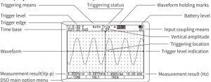
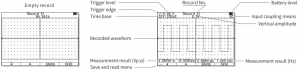
Basic displayed items under the scopemeter mode
The function buttons of F1~F4 are located at the lower of the LCD screen. With the option menu on the screen, these buttons will enable users to realize several functions. Some functions are provided with sub-option menu for further operations. Please refer to relevant later sections for the usage of these option menu and optional option menu.
The main option menu provides the instructions for basic operations of the instrument and the details are as follows:
|
Horizontal adjustment |
Vertical adjustment | Triggering control |
Cursor function |
|
TIME |
VOLT | TRIG |
CURS |
|
F1 |
F2 | F3 |
F4 |
- Press F1 button (TIME) to enter into sub-option menu of time base setting and adjust the scanning time base and triggering position
- Press F2 button (VOLT) to enter into sub-option menu of vertical sensitivity setting and adjusts the vertical amplitude and waveform position
- Press F3 button (TRIG) to enter into sub-option menu of trig setting and adjust the trigger level, gradient and mode. 4. Press F4 button (CURS) to enter into cursors measurement function. This function is valid only after completion of waveform holding or single-time scanning and is not displayed at other time
Selection of coupling means of input signal
The selected input coupling will determine what part of signal is allowed to be transmitted to the scopemeter. The coupling means include DC/AC types.
|
DC coupling |
The AC and DC part of signal is allowed pass through. |
|
AC coupling |
The DC part of signal is blocked but the dynamic AC part is allowed to pass through. |
Time base control
Under the main option menu of scopemeter, press F1 button to enter into the sub-option menu of scanning time base control:
|
Back |
Adjustment of scanning time base |
Horizontal position |
|
|
EXIT |
◄ | ► |
POS |
|
F1 |
F2 | F3 |
F4 |
- Press F1 button (EXIT) to exit the sub-option menu of time base setting and back to the main option menu.
- Press F2 button (◄) and F3 button (►) to adjust the time base (t /div).
- Press F4 button (POS) to enter into the sub-option menu of adjustment of triggering position (horizontal position)
Instructions!
- When measuring a signal whose frequency is unknown, user has to try to collect the waveform from the fastest time base and then gradually select the slower time base until the signal can be displayed correctly. Otherwise, due to “aliasing effect”, waveform may fail to correctly reflect the actual situation of the signal.
- There are several ways to avoid aliasing effect: adjust the time base or press“R”button.
Adjustment of horizontal position
Under the sub-option menu of scanning time base setting, press F4 button (POS) to enter into the sub-option of adjustment of triggering position. With the change of triggering position, the horizontal position of waveform will change accordingly. Therefore, the adjustment of triggering position is also referred to as adjustment of horizontal position.
|
Back |
Adjustment of horizontal position |
Center the horizontal position |
|
|
EXIT |
◄ | ► |
RESET |
|
F1 |
F2 | F3 |
F4 |
- Press F1 button (EXIT) to exit the sub-option menu of adjustment of waveform horizontal position and back to the sub-option menu of scanning time base setting.
- Press F2 button (◄) and F3 button (►) to adjust the position of scanning trigger point and the horizontal position of waveform on the screen is changed accordingly. The current scanning trigger point is marked on the monitor.
- Press F4 button (RESET) to set the trigger point to default position (the right center of the screen).
Vertical amplitude control
Under the main option menu of scopemeter mode, press F2 button (VOLT) to enter into the sub-option menu of vertical control:
|
Back |
Adjustment of vertical sensitivity |
Vertical position |
|
|
EXIT |
▼ |
▲ |
|
|
F1 |
F2 | F3 |
F4 |
- Press F1 button (EXIT) to exit the sub-option menu of vertical control and back to main option menu.
- Press F2 button (▼) and F3 button (▲) to adjust the vertical amplitude (V/div).
Instruction!
To ensure the stability of circuit inside the instrument, the movement of adjustment of sensitivity may be a little delayed during adjustment of vertical sensitivity by pressing F2 button or F3 button.
Trigger control
Under the main option menu of scopemeter mode, press F3 button (TRIG) to enter into the sub-option menu of trigger setting:
|
Back |
Trigger edge | Triggering mode |
Trigger level |
|
EXIT |
MODE |
LEVEL |
|
|
F1 |
F2 | F3 |
F4 |
- Press F1 button (EXIT) to exit the sub-option menu of trigger setting and back to the main option menu.
- Press F2 button ( or ) to select the rising or descending edge. triggering.
- Press F3 button (MODE) to select the trigger mode.
- Press F4 button (LEVEL) to enter into the sub-option menu of adjustment of trigger level
Adjustment of trigger level
Under the sub-option menu of trigger setting, press F4 to enter into sub option menu of adjustment of trigger level
|
Back |
Adjustment of trigger level |
Reset of trigger level |
|
|
EXIT |
▼ | ▲ |
RESET |
|
F1 |
F2 | F3 |
F4 |
- Press F1 button (EXIT) to exit the sub-option menu of adjustment of trigger level and back to the sub-option menu of trigger setting.
- Press F2 button (▼) and F3 button (▲) to reduce or increase trigger level. The current corresponding position of trigger level is marked on the monitor.
- Press F4 button (RESET) to set the electrical level to 0 volt.
About the trigger mode
Automatic: Even if no trigger conditions are detected, the scopemeter can still collect waveforms. If there are no trigger conditions, the scopemeter will be automatically triggered and start to collect data after waiting for a certain period of time. As it’s not correctly triggered, the waveform displayed by the scopemeter will scroll on the screen due to failure of synchronization. Once legal trigger signals are detected, the waveform will become stable on the screen. User may use this mode to monitor low-frequency irregular signal or observe the amplitude of signals, such as waveform of DC power etc.Normal: After trigger signals are detected, the scopemeter will start collecting waveform data. If there is no triggering, the scopemeter will not collect new waveforms. The content of monitor will not be refreshed.Single : In single-time mode, once trigger conditions are detected, the scopemeter will start to collect waveform data. After new data is collected, the latest waveform will be automatically saved.
Prompt message of scanning status
|
Auto |
Automatic mode. Waveform can be collected even without trigger conditions. |
|
Ready |
Waiting for trigger conditions. |
|
Trigger |
Trigger conditions has been detected. |
Trigger operations of single scan
The data collection of single trigger is carried out in the following steps:
- Adjust the vertical amplitude V/div and horizontal amplitude to adapt to the waveform to be collected.
- Select appropriate trigger level, gradient and then select single trigger mode.
- Once signals are appeared, the scopemeter will be triggered to capture the signals.
Instructions!
After waveform is held, press F4 button to activate the cursor measurement function; press “S” button for 2 seconds to save the waveform.One single trigger mode is selected, any adjustment to waveform will be prohibited. If you want to change scanning time base, vertical amplitude, coupling means and waveform position etc., please press F3 button (TRIG) to activate the adjustment of trigger mode and adjust the trigger mode to automatic mode or normal mode.

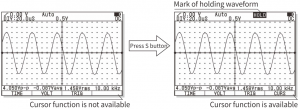
Cursor measurement reading function
The cursor measurement reading function can be used to measure the voltage difference (ΔV) or time difference (Δt) between the two cursors on the monitor. When ΔV measurement function is selected, the scopemeter will generate a pair of horizontal cursors; whenΔt measurement function is selected, the scopemeter will generate a pair of vertical cursors. The voltage difference or time difference between cursors will be displayed on the screen from time to time.
The cursor measurement reading function is only available when the waveform is held (Use HOLD or single time scan). After the waveform is held, press F4 button to enter into sub-menu of cursor measurement reading function:
|
Back |
Voltage difference |
Time difference |
|
EXIT |
DV |
Dt |
|
F1 |
F2 |
F3 |
The operation of the cursor measurement readout function is as follows:
- Press F1 button (EXIT) to exit the cursor measurement reading function.
- Press F2 button (ΔV) to activate the voltage difference measurement and enter into the sub-option menu of ΔV measurement. This allows the measurement of voltage difference between the upper and lower cursors i.e. the crest of measured waveform—-peak value.The sub-option of voltage difference (ΔV) measurement is as follows:
Back
Adjustment of cursor position Selection of cursor
EXIT
▼ ▲ UPPER
F1
F2 F3 F4
a. Press F1 button (EXIT) to exist the sub-option menu of voltage difference measurement and back to the sub-option menu of cursor control.b. Press the F2 key (▼) and the F3 key (▲) to adjust the position of the cursor. c. Press F4 button to switch for upper or lower cursor (UPPER/LOWER).
- Press F3 button (Δt) to activate the time difference measurement and enter into the sub-option menu of Δt measurement. This allows the measurement of time difference between the left and right cursors and the corresponding frequency i.e. measurement of pulse width or cycle/frequency of signalsThe sub-option menu of time difference (Δt) is as follows:
Back
Adjustment of cursor position Selection of cursor
EXIT
◀ ▶ LEFT
F1
F2 F3 F4
a. Press F1 button (EXIT) to exit the sub-option menu of time difference measurement and back to the sub-option menu of cursor control.b. Press F2 button (◀) and F3 button (▶) to adjust the location of cursor.c. Press F4 button to switch for left or right cursor (LEFT/RIGHT)
Automatic measurement of waveform
The scopemeter is able to automatically measure the amplitude and frequency of current waveform. The measurement result is more accurate than visual observation or cursor measurement. The measurement result is displayed beneath the waveform. The measurement result of amplitude is displayed on the left side and that of frequency is displayed on the right side. The measurement result of amplitude can be crest of waveform—-peek value, mean value or virtual value.
|
Instructions! |
These measurement results are based on the calculation of displayed waveform. Obviously, the smaller the amplitude of signals, the greater the error. When the amplitude of signals is too small, the instrument will mark the measurement result with “?”, so as to remind user to correctly understand the measurement result. On the other hand, when the amplitude of signals is too big and is close to or exceeds the measuring range of the instrument, the instrument will also mark a “?” to call for user’s attention. |
Holding of signal waveform
When collection of data is continuing, the waveform of signals will be constantly refreshed. When the data collection is stopped, the display content will be held. The main purpose of holding waveform is to hold the current data or waveform, so as to make close observation easier. The current wave also has to be held before it is stored into database. There are two methods for holding wavedata: Press “S” button or use single trigger scanning mode. Press “S” button to start or stop the collection of waveform data. Once the collection of wavedata by the scopemeter is ceased, the display is held.
When scanning speed set to 200ms/div or a faster time base, after pressing “S” button, user will immediately hold the last waveform on the screen. If the instrument is set to 50ms/div or a slower time base, the instrument will hold the waveform when scanning by rolling. The instrument will automatically transmit the earliest data display to the left of the screen to maintain the continuity of waveform.
|
Instructions! |
After waveform is held, press F4 button to activate cursor measurement function (fast movement of cursor will probably cause blurring screen due to delayed response of monitor; in such case, user may exit and get back to measurement status for recovery); press “S” button for 2 seconds to enter into database and save the waverform. Once waveform is held, any adjustment of waveform will be disabled. If you need to change scanning time base, vertical amplitude, coupling means and wave position etc., you may press “S” button and restart the collection of waveform data.
|
Storage and reading of waveform of signals
The OSC database of the instrument is provided with a memory space for 50 OSC waveform data. The operation method of the storage is as follows:
- Press “S” button for 2 seconds and enter into the database.
- If user needs to save current waveform, user may press “S” button to hold current waveform, or use single-time scanning to get held waveform; press “S” button again, and the monitor will list the status of storage position of the first page.
- Press “S” button to exit database.The option menu of database is as follows:
Page up
Page down Delete Save
◀
▶ ERASE SAVE
F1
F2 F3 F4
a. Press F1 button (◀) to select the next data position in order.b. Press F2 button (▶) to select the next page in order.c. Press F3 button (ERASE) to erase the waveform at current page.d. Press F4 button (SAVE) to save current held wave on current page.
Instructions!
- If user wants to save current waveforms and data, use has to hold these waveforms first. Otherwise, the reminding of function button F3 (SAVE) will not appear.
- If the new waveform is saved to a position where original waveform has been saved, the original waveform will be replaced. Therefore, user has to be careful during operation, so as to prevent loss of useful data.
After accessing the memory waveform reading function, all stored waveforms and relevant parameters will be displayed on the screen. The waveform automatic measurement result will also be displayed. The amplitude measurement result can be the crest of waveform—–peak value, mean value and virtual value.The option menu under the memory waveform display status is as follows:
Page up
Page down Delete Cursor measurement
◀
▶ ERASE CURS
F1
F2 F3 F4
a. Press F1 button (◀) to read the previous waveform.b. Press F2 button (▶) to rest the next waveform.c. Press F3 button (ERASE) to delete the waveform on current page.d. Press F4 button (CURS) to access cursor reading function.


Operations of multimeter
Entering into the mode of multimeter
Rotate the rotary knob to select the mode of multimeter (DMM)
|
Warning! |
|
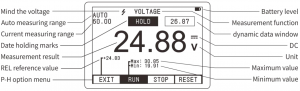
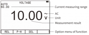
Basic content displayed under multimeter mode
The following are the basic content displayed under DMM status. Please note that the symbols in the picture do not include the entire character set of the instrument and that these symbols do not necessarily appear at the same time.
Switching measurement function
Rotate rotary button for selection of test function. The switching of measurement function follows the following circulation order: voltage (AC/DC)/frequency/duty ratio resistance/diode/continuity/capacitance temper a turetriodemA current (AC/DC) 10A current (AC/DC) AC waveform DC waveform. For multi-functional gear, press F3/SEL for switching of functions; for voltage and current gear, press F3/SEL for switching to AC/ DC/Hz/%.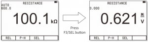
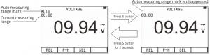
Selection of manual/automatic measuring range
Automatic measuring range is adopted after start-up or switching to measurement function. For most occasions of application, this is the most convenient measuring method. On occasions where a certain measuring range shall be fixed, user may perform the following operations:
- Press “R” button and the mark of automatic measuring range “AUTO” will disappear and the instrument enters into manual measuring state.
- At each time when “R” button is pressed, the instrument will be switched to the next measuring range.
- Press “R” button for 2 seconds, the instrument will return to automatic measuring state.
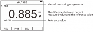
Relative value measuring mode
Relative value mode is a measuring mode which displays the difference between the actual measurement value and the reference value. Relative value mode is available for most functions of the instrument.
- Press F1 button (REL) and the current displayed measurement value will be saved as the reference value. Then, the relative value mode is activated.
- The value displayed on the screen is the difference between the current measured value and the expected reference value.
- Press F1 button (REL) to exit relative value mode.
- After entering into relative value mode, the measuring range control mode of the instrument will be automatically switched to manual mode.
- When the measuring function or measuring range is changed, the relative value mode will be automatically
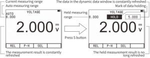
Holding of measurement data
Press data holding button “S”, the displayed reading will be held. At this time, the icon of data holding “HOLD” will be displayed on the LCD screen. Press “S” button again, normal operation will be resumed.
- After the data is held, press “S” button for 2 seconds to access to database function. In this way, the data is saved.
- Under the data holding state, a small window (dynamic data window) will appear on the upper right corner of the screen. The data in the window is still constantly refreshed.
- Once the instrument is in data holding state, the measuring range control mode will be switched to manual mode.
- When the measuring range or measuring function is changed, the instrument will automatically exit the holding state.
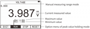
Peak value holding (P-H) mode
The peak value holding mode will display the measured maximum value and minimum value. These values are constantly refreshed accordingly based on each time of refresh of measurement result. The peak value holding mode is available for most functions of the instrument. User may press F2 button (P H) to activate this function. The maximum and minimum peak value of measured data will be displayed on the LCD.
The menu of peak value holding mode is as follows:
|
Exit the peak value holding |
Run measurement | Stop measurement |
Reset peak value |
|
EXIT |
RUN | STOP |
RESET |
|
F1 |
F2 | F3 |
F4 |
a. Press F1 button (EXIT) to exist the peak value holding mode.b. Press F2 button (RUN) to run measurement of peak value.c. Press F3 button (STOP) to stop refreshing peak value measurement. The current maximum/minimum value will be no longer changed.d. Press F4 button (RESET) to reset the measured peak value and restart new measurement
|
Instructions! |
|
AC and DC voltage measurement
|
Instructions! |
When the measured voltage exceeds the “safety voltage” (24VDC/AC), the warning information “ |
|
Warning! |
|
- Plug the banana plug of the black test line into the negative COM socket and the banana plug of the red test line into the positive “V” socket.
- Rotate the rotary knob to select the “ ” function. A sign of “VOLTAGE” will appear on the top of the screen to remind user that the function of voltage measurement is currently available.
- Press F3 button to switch to DC/AC/Hz/% measuring mode (the default mode is DC).
- Use test lead to touch the test point.
- The instrument will display the value of voltage. The displayed result includes the value, decimal point and polarity. The option menu of voltage measurement is as follows:
Relative value mode
Peak value holding mode Extended measuring function
REL
P-H SEL
F1
F2 F3
a. Press F1 button (REL) to enter into relative value mode.b. Press F2 button (P-H) to enter into peak value holding mode.c. Press F3 button (SEL) to select other functions: DC, AC, frequency Hz, duty ratio %.
Measurement of AC and DC current (500mA, 10A
|
Warning! |
|
- Plug the banana plug of the black test line into the negative COM socket and the banana plug of the red test line into the positive 500mA or 10A socket.
- Rotate the rotary knob to select “ mA” or “ 10A” function. Then, a sign of “CURRENT” will appear on the top of the screen to remind user that the function of current measurement is currently available.
- Press F3 button to switch to DC, AC, Hz, % measuring mode.
- Add the test lead in series with the circuit to be tested. The instrument will display the value of current, decimal point and polarity.
The option menu of current measurement is as follows:
|
Relative value mode |
Peak value holding mode |
Extended measuring function |
|
REL |
P-H |
SEL |
|
F1 |
F2 |
F3 |
a. Press F1 button (REL) to enter into relative value mode.b. Press F2 button (P-H) to enter into peak value holding mode.c. Press F3 button (SEL) to select other functions: DC, AC, frequency Hz, duty ratio %.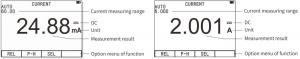
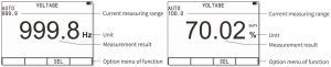
Frequency counting and measurement of duty ratio
The instrument adopts FIV (Frequency in Voltage) and FIX (Frequency in Ampere) for the measurement of frequency/duty ratio. In this way, the frequency counting and duty ratio also become extended function of the function of voltage and current measurement.
- Plug the banana plug of the black test line into the negative COM socket and the banana plug of the red test line into the positive V/mA or 10A socket.
- Rotate the rotary knob to select the voltage or current measurement function and choose appropriate measuringrange to read current voltage or current value.
- Press F3 (SEL) to select extended function: frequency and duty rat
|
Attention! |
To measure the frequency and duty ratio, the signal must reach certain amplitude: the voltage signal amplitude shall be ³ 500mVp-p; the current signal shall be ³ 20mA RMS. For signals which are close to 10MHz or higher, a large amplitude of (voltage/current) signal may be required. |
|
Attention! |
When carrying out frequency counting and measurement of duty ratio, manual mode shall not be adopted and the function of relative value (REL) and Peak value holding shall not be used either. |
|
Instruction! |
For higher frequency, the automatic measurement function under scopemeter mode may be utilized. |
Resistance measurement
|
Warning! |
To avoid electricity shock, before the resistance measurement, user shall first cut off (taking out the battery/ remove the power line) the power of the device to be tested and discharge the capacitor of the power. |
- Plug the banana plug of the black test line into the negative COM socket and the banana plug of the red test line into the positive resistor socket.
- Rotate the rotary knob to select “ ” measurement function. Then, a sign of “RESISTANCE” will appear on the top of the screen to remind user that the function of resistance measurement is currently available.
- Bridge the test lead over the circuit or component to be tested. The tested part online is better to be removed from the original circuit connection, so as to ensure other part of the circuit will not affect its correct reading.
- The instrument will display the value of resistance, unit and decimal point.
The operation option menu of resistance measurement is as follows:
|
Relative value mode |
Peak value holding mode |
Extended measuring function |
|
REL |
P-H |
SEL |
a. Press F1 button (REL) to enter into relative value mode.b. Press F2 button (P-H) to enter into peak value holding mode.c. Press F3 button (SEL) to enter into extended functions: diode test, continuity test and capacitance measurement.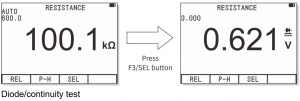
Diode test
|
Warning! |
To avoid electricity shock, please do not test the diode with load of voltage. |
- Plug the banana plug of the black test line into the negative COM socket and the banana plug of the red test line into the positive resistor socket.
- Rotate the rotary knob to select “ ” measurement function. Then, a sign of “RESISTANCE” will appear on the top of the screen to remind user that the function of resistance measurement is currently available.
- Press F3 button (SEL) to select the function of diode test.
- Bridge the test lead over the two ends of diode or semiconductor PN junction. Please note the reading of the instrument.
- Interchange the test leads to reverse the polarity. Please note the reading of the instrument.
- The nature of the diode or semiconductor PN junction may be judged from the following:If a reading at one time displays a voltage value (about 0.2V to 0.7V) and a reading at another time displays “O.L”, then this diode is good. If the reading of both times displays “O.L”, there is break circuit with the diode. If the reading of both times is very small or 0, there is short circuit with the diode.Continuity test
Warning!
To avoid electricity shock, please do not perform continuity test of circuit with load of voltage.
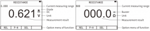 Continuity test
- Plug the banana plug of the black test line into the negative COM socket and the banana plug of the red test line into the positive resistor socket.
- Rotate the rotary knob to select “ ” measurement function. Then, a sign of “RESISTANCE” will appear on the top of the screen to remind user that the function of resistance measurement is currently available.
- Press F3 button (SEL) to select the function of continuity test.
- Use the test lead to touch the circuit to be tested. If the resistance is smaller than 50Ω, the buzzer will sound
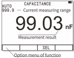
Capacitor measurement
|
Warning! |
To avoid electricity shock, please do not test the capacitor with load of voltage. |
- Plug the banana plug of the black test line into the negative COM socket
- Plug the banana plug of the red test line into the positive CAP socket.
- Rotate the rotary knob to select “ ” measurement function. Then, a sign of “RESISTANCE” will appear on the top of the screen to remind user that the function of resistance measurement is currently available.
- Press F3 button (SEL) to select the function of capacitor measurement. Then, a sign of “CAPACITANCE” will appear on the top of the screen to remind user that the function of capacitor measurement is currently available.
- For capacitor measurement, the measuring range mode can only be automatic mode.
- Use the test lead to touch the capacitor to be tested and read the capacitance, decimal point and unit etc.
|
Attention! |
Manual measuring range cannot be adopted for the function of capacitance measurement and the function of relative value (REL) and Peak value holding shall not be used either. |
Temperature measurement
- Insert standard K type temperature sensor into the negative COM socket and the positive TEMP (Mind the polarity)
- Rotate the rotary knob to select “ ” measurement function. Then, a sign of “TEMPERATURE” will appear on the top of the screen to remind user that the function of temperature measurement is currently available.
- Use the probe of sensor to touch the liquid or surface of object whose temperature is to be measured and read the displayed temperature (Centigrade or Fahrenheit).

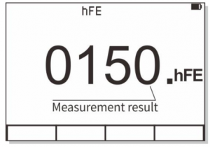
Measurement of amplification factor of triode
- Rotate the rotary knob to select “hFE” measurement function. Then, a sign of “hFE” will appear on the top of the screen to remind user that the function of measurement of amplification factor of triode is currently available.
- Insert the pin of triode to be tested into the corresponding EBC plugs of NPN or PNP type triode based on their polarity.
- Read the amplification factor of triode.
Storage and reading of measurement data
The database of the instrument is able to save 100 DMM measurement data.
- Press “S” button for 2 seconds to enter into the database of the instrument.
- If user needs to save current measurement value into database, use shall first press “S” button to hold this data. Then, press “S” button for 2 seconds to enter into the database.
- In the database, LCD will list the 10 storage position of the first page and indicate where there is data on such positions.
- If there is data on a certain position, the value and unit of the data will be also listed.The operation option menu of database is as follows:
Select record position
Select a neighboring page Delete record Save held data
▼
▶ ERASE SAVE
F1
F2 F3 F4
a. Press F1 button (▼) and the selection marks points to the next storage position. Press F1 button for 0.5 seconds for invert selection of the previous storage position.b. Press F2 button (▶) and the selection marks points to the next page. Press F2 button for 0.5 seconds for invert selection of the previous page.c. Press F3 button (ERASE) to delete current record. d. Press F4 button (SAVE) to save the held data to the currently selected storage position.
- Press “S” button again to exit the database function.
Instructions!
If you want to save data, you need to hold the data first. If the data is not held, the F4 mark SAVE will not appear after you enter into the database.If the data is saved to a recording position where original data has been saved, the original data will be replaced. Therefore, user has to be careful during operation, so as to prevent loss of useful data.

Technical Parameters and the entire set of instrument
Features and technical parameters of the instrument
General features
| Display | 240*160dot-matrix graphics | Observation area | 60mm x 40mm |
| Backlight | Constantly on | Input resistance | 10MΩ |
| Battery | 3 AA5 batteries | Auto shutdown | 15 minutes or disabled |
| Power shortage | Operation height | 0~2000m | |
| Use time | More than 8 hours | Storage capacity | 100/Data, 50/ Waveform |
| Use environment | 0°C~+40°C;<75%RH | Storage condition | -10°C ~ +60°C ; <90%RH |
| Overall dimension | 83 mm ´ 160 mm ´ 32mm | Weight |
Feature of digital storage scopemeter
| Analog bandwidth | 40MHz | Maximum real-time sampling rate | 200Msps |
| Vertical resolution | 8 bits | Degree of nonlinearity | ±1 bit |
| Number of channels | 1 | Coupling means | DC/AC |
| ccc | About 100MΩ | Division | Vertical ± 6.0, horizontal 24.0 |
| Range of vertical sensativity | 500mV/div ~ 200V/div | Range of time base | 12.5ns/div ~ 10s/div |
| Accuracy of vertical amplitude | ±(5%+ 0.2div) | Accuracy of time base | ±(0.01% + 0.1div) |
| Automatic zero point reference | During DC measurement | Scanning mode | Auto/normal/single |
| Trigger level | ± 6 div (0.1div/step) | Selection of trigger gradient | Rising/descending edge |
| Adjustment of trigger
position |
± 12 div (0.1div/step) | Automatic setting | Automatic setting of time base and vertical amplitude |
| Cursor measurement
function |
dV, dt, 1/dt (Frequency) | Automatic measurement function | Vp-p, Vavg, Vrms |
| Auto measurement accuracy | ±(5%+ 0.2div) | Length of recording | 24.0div |
* Where the analog bandwidth is 40MHz and the voltage is reduced to 3db, if there is interference to the input signal, adapters and special high-frequency shielding lines may be used.* The vertical dilution is 1-2-5 measurement range switching.
Features of digital multimeter
The uncertainty of all measuring ranges is indicated as: ± (a% reading + number). The calibration is valid for one year after which it shall be adjusted. The environmental conditions for ensuring the uncertainty are: 23°C±5°C, <75%RH (mV measuring range can be switched only through manual measurement.
| Function | Measuring range | Resolution | Uncertainty |
| DC voltage | 600.0mV | 0.1mV |
± (1.0%rdg + 10dgt) |
| 6.000V | 1mV | ||
| 60.00V | 10mV | ||
| 600.0V | 100mV | ||
| 1000V | 1V | ± (1.5%rdg + 10dgt) | |
| AC voltageTrue virtual value | 600.0mV | 0.1mV | 50Hz~400Hz ± (1.5%rdg + 10dgt) 400Hz~1kHz (for reference only if it’s above 1kHz) ± (2.0%rdg + 10dgt) |
| 6.000V | 1mV | ||
| 60.00V | 10mV | ||
| 600.0V | 100mV | ||
| 750V | 1V | ± (2.0%rdg + 10dgt) | |
| (50Hz~400Hz) | |||
| DC current | 60.00/500.0mA | 10µA /100µA | ± (1.2%rdg + 10dgt) |
| 6.000/10.00A | 1mA /10mA | ||
| AC current true virtual value | 60.00/500.0mA | 10µA /100µA | ± (1.5%rdg + 10dgt) 50Hz~1kHz (for reference only if it’s above 1kHz) |
| 6.000/10.00A | 1mA /10mA | ||
| Resistance | 600.0W | 0.1 Ω |
± (1.2%rdg + 5dgt) |
| 6.000kW | 1 Ω | ||
| 60.00kW | 10 Ω | ||
| 600.0kW | 100 Ω | ||
| 6.000MW | 1kW | ||
| 60.00MW | 10kW | ± (3.0%rdg + 10dgt) | |
| Capacitance | 9.999nF | 1pF | ± (3.0%rdg + 10dgt) |
| 99.99nF | 10pF | ||
| 999.9nF | 100pF | ||
| 9.999μF | 1nF | ± (3.0%rdg + 10dgt) | |
| 99.99μF | 10nF | ||
| 999.9μF | 100nF | ||
| 9.999mF | 1μF | ± (5.0%rdg + 10dgt) | |
| 99.99mF | 10μF | ||
| Temperature | 0℃~600℃ | 0.1℃ | ± (2.0%rdg + 10dgt) |
| Triode | 1~1999 | 1 |
Symbols and icons
| A | ampere | AC ~ | Alternate current |
| AUTO | Auto measuring range/auto
scanning/auto setting |
AVG, avg | Average value |
| CURS | Cursor | COM | Reference end of measurement (near the socket of input reference end) |
| DC | Direct current | mV | millivolt |
| div | Division (Scopemeter mode) | DUTY | Duty ratio |
| ERASE | Erase record | EXIT | Exit current state or option menu |
| F | Farad (Unit of capacitance) | hFE | Amplification factor of triode |
| HOLD | Data/waveform holding | Hz | Hertz (Unit of frequency) |
| P-H | Peak value holding | LEVEL | Trigger level |
| LEFT | Select left cursor | LOWER | Select lower cursor |
| MANUA | Manual selection of measuring range | MAX | Maximum value |
| mA | milliampere | mF | Millifarad (unit of capacitance) |
| MIN | Minimum value | ms | Millisecond |
| NORM | Normal trigger means | nF | Nano-farad (unit of capacitance) |
| POS | (Horizontal/vertical) position | RANGE | Manual selection of measuring range |
| READ | Read waveform/data in the memory | READY | Ready to be triggered |
| REL | Relative value | RESET | Reset or back to centered position |
| Restore | Restore original setting | RIGHT | Select right cursor |
| SAVE | Save current signal to memory | RUN | Make recording in MIN/MAX mode |
| SETUP | Setting | Single | Single-time waveform |
| STOP | Stop the “MIN/MAX” function | TEMP | Temperature measurement °C/°F |
| TIME | Time, time base | TRIG | Scan trigger |
| UPPER | Select upper cursor | V | volt |
| VOLT | Voltage, input sensitivity | μF | Microfarad (unit of capacitance) |
| μs | microsecond | μS | Micro siemens (unit of conductivity) |
| Ω | Ohm (unit of resistance) | ΔV | Voltage difference |
| Δt | Width of time difference of signals | ▲▼ | Option adjustment or (upward/downward) movement of cursor |
| ◀ ▶ | Option adjustment or (leftward/
rightward) movement of cursor |
|
Remaining capacity of battery |
|
|
Trigger gradient (rising edge/descending edge) |  |
Sounding, continuity test |
| Power switch and an icon displayed
1 minute before automatic sleep |
Diode | ||
| Safety warning (harmful or extreme voltage or current reminding) |
Entire set of instrument and optional fittings
Standard fittings of instrument: one mainframe, a pair of low-noise test leads, one Proof Canvas bag and one product manual
Daily maintenance and troubleshooting
Keep the instrument dry
If the instrument is wet, please wipe it until it’s dry. If you are not sure whether it’s dry, please do not use it.
Use and store the instrument in ambient temperature
Extreme ambient temperature will reduce the service life of electric components, deform plastic parts or even cause non-availability for use of the instrument.
Handle the instrument with care
Fall may cause damage to liquid crystal display, electric components or housing.
Keep the instrument clean
Use a piece of wet cloth dipped with a little of detergent to wipe the housing of the instrument often. Do not use rough objects, chemical solutions or alcohol etc.
Replacement of protective tube
- Remove the probe from test point and shut down the power.
- Loosen the fixing screw and take off the back cover. The protective tube is at the back side of the test socket.
- Take out the burnt protective tube and replace it with a new one of the same specification: for 500mA current, the 500mA /250V fuse type protective tube is used; for 10A current, the 10A/250V fuse type protective tube is used.
- Put back the back cover and fixed it with screws.
Repair and maintenance of the instrument
- This is a precision instrument. Without the authorization of the products center of the company, please do not alter any circuit, replace any component or perform any calibration or repair of the product.
- All test leads, accessories or optional fittings of the instrument cannot be replaced, repaired or substituted randomly.
Warning! Before opening the back cover of the battery, please make sure to disconnect the probe from any probe of voltage. Before the back cover is closed and fixed, please do not use this instrument.
Troubleshooting
In case of any failure of the instrument, please check the following by yourself before deciding to send it for repair.
No display on the screen and no response of buttons
1. No power is available. Please make sure the batter of the instrument is not exhausted and the battery and battery plate are in good condition and correctly connected.2. Rotate the rotary knob to the power-off position and then rotate it to the measurement position.
Incorrect voltage reading
- The reference point of zero voltage of OSC mode is incorrect.
- When measuring virtual value (RMS) under OSC mode, please make sure there is at 1 complete cycle of waveform display.
Failure of display of waveform or incorrect frequency measurement of OSC
- The time base setting is incorrect. You may try automatic setting.
- The instrument is in waveform holding (HOLD) mode or single-time (Single) scanning mode.
- The waveform has not reached the trigger mode. Please try automatic setting.
- The input signal is too large or there is error with vertical position. You may re-adjust the vertical amplitude (Volt/div) or try the automatic setting.
Failure of measurement of current
The protective tube is burnt. Please replace the protective tube.
Oscilloscope Multimeter Users Manual 6102 – Oscilloscope Multimeter Users Manual 6102 –
[xyz-ips snippet=”download-snippet”]