Pandora Radio relay BT-02 User Guide
Peripheral devices, designed to expand the functional of the Pandora security system or to work separately with the direct control by the mobile application Pandora Relay (iOS/Android). Available functions of the system: LIN – digital control of the engine heaters, IN BT1 / IN BT2 – programmableinputs, CH BLE R1 – programmable built-in relay. Available functions of the application: CH BLE R1 – constant or timed (1 – 60 sec) control of the built in relay
SPECIFICATION
Nominal voltage: +12V Current com of the relay: <1mASwitching current of the built-in relay: min 10mA, nom 1A, max 2A2,4 GHz radio protocol: Bluetooth 4.2 Low Energy Degree of protection: IP64Operating temperatures: from -40°C to +85°C Dimensions: 39x16x13 Dimensions: 39x16x13


PROGRAMMING
- Enter the programming level №10.6 (see «Programming table» section of the system manual) or use the «Pairing» function in the Pandora Specialist mobile app (go to «Advanced mounting»-> «Bluetooth»-> «Pairing, upcoming devices»).
- Connect the wire №1 (red) to a reliable +12V power supply.
- Connect the wire №7 (black) with the wire №8 (green/yellow). Connect them to the grounded spotof a vehicle.
- The successfully pairing will be conform by the sound signal of the Siren/Beeper, or by a request to pairthe device in the mobile app Pandora Relay.
- Disconnect the wire №8 (green/yellow), insulate all unused wires.
! THE RADIO RELAY COULD BE PAIRED WITH ONLY ONE SECURITY SYSTEM OR A SMARTPHONE
INSTALLATION MANUAL
! BEFORE STARTING THE INSTALLATION, THE RADIO RELAY MUST BE PAIRED, CONFIGURATED AND CHECKED.
The radio relay is designed for a hidden installation in the interior or engine compartment of a vehicle withon-board voltage of +12V. While installing the relay: – do not shield the relay (minimum distance of 20 mm between the relay and metal parts); – provide a rigid fastening to the car body or the fixed wirings (it is forbidden to hide the module in the fix wiring); – install the relay in places where there are no any liquids, condensate and high temperatures. The relay must be installed with wires down, each wire must be insulated, excluding the tension of the connection points.
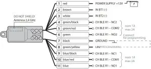
- WIRE №1 I POWER SUPPLY +12V
- The wire should be connected to a reliable conductor with aconstant voltage of +12V.
- WIRE №2, №3 I IN BT1(-), IN BT2V
- the wires of the programmable input channels. They are and operate according to the programmed in the system logic. Inputs logic IN BT1, IN BT2 must beassigned in the «Inputs» or «Time channels» menu.
- WIRE №7 I GROUND (-)
- This wire must be connected to the grounded spot of a vehicle. •
- WIRE №8 I LIN/PROGRAMMABLE channel
- The wire must be connected to the wire №7 during pairing procedure (see «PROGRAMMING» section). It can be used for management of the engine preheater. Go to the «Automatic start»->«Engine preheater»->«Use LIN RHM to control engine preheaters» menu and choose Website or option (This setting will also apply to the RHM 03BT module, if installed).
- WIRES №4/№5/№6/№9/№10/№11 I CH BLE R1
- the wires of the built-in relays with twofull groups of contacts. The built-in relays are configured and operate according to the programmed in the system logic. Output’s logic BLE R1 must be assigned in the «Outputs» or «Time channels» menu.
- the wires of the programmable input channels. They are and operate according to the programmed in the system logic. Inputs logic IN BT1, IN BT2 must beassigned in the «Inputs» or «Time channels» menu.
! THE SWITCHING CURRENT OF THE BUILT-IN RELAY SHOULD NOT EXCEED 1A FOR A CONTINUOUS LOAD AND 2A FOR SWITCHING WITHOUT AN INDUCTIVE LOAD

[xyz-ips snippet=”download-snippet”]