Parasound JC 3 Jr Phono Preamplifier Owner’s Manual
Important Safety Instructions
The lightning flash with the arrowhead symbol within an equilateral triangle is intended to alert the user to the presence of “dangerous voltage” inside the product that may constitute a risk of electric shock. The exclamation point within an equilateral triangle is intended to alert the user to the presence of important operating and maintenance instructions in the literature accompanying the product. TO REDUCE THE RISK OF ELECTRIC SHOCK, DO NOT REMOVE COVER. NO USER-SERVICEABLE PARTS INSIDE. REFER SERVICING TO QUALIFIED SERVICE PERSONNEL
- Read Instructions — Read all the safety and operating instructions before operating this product.
- Retain Instructions — Retain safety and operating instructions for future reference.
- Heed Warnings — Adhere to all warnings on the product and in the operating instructions.
- Follow Instructions — Follow all operating and use instructions.
- Cleaning — Unplug this product from the wall outlet before cleaning. Use a damp cloth for cleaning. Clean the outside of the product only.
- Attachments — Do not use attachments that are not recommended by the product manufacturer; they may be hazardous.
- Water and Moisture — Do not use this product near water.
- Accessories — Do not place this product on an unstable cart or stand. The product may fall, causing bodily injury and damage to the product. A product and cart combination should be moved with care. Quick stops, excessive force, and uneven surfaces may cause the product and cart to overturn.
- Ventilation — Slots and openings in the cabinet are provided for ventilation to ensure reliable operation of the product and to protect it from overheating. These openings must not be blocked or covered. This product should not be placed in a built-in installation such as a bookcase or rack unless proper ventilation is provided.
- Power Sources — Operate this product only from the type of power source indicated on the label. If you are not sure of the type of power supply to your home, consult your dealer or local power company. This product is equipped with a three-prong grounding plug. This plug will only fit into a grounding power outlet. If you are unable to insert the plug into the outlet, contact your electrician to replace your obsolete outlet. Do not defeat the safety purpose of the grounding plug.
- Power Cord Protection — Power supply cords should be routed so that they are not likely to be walked on or pinched by items placed upon or against them.
- Lightning — Unplug the unit from the wall outlet for added protection during a lightning storm and when it is left unattended and unused for long periods of time. This will prevent damage to the product due to lightning and power line surges.
- Overloading — Do not overload wall outlets or extension cords. This can result in a fire or electric shock.
- Inserting Objects into Unit — Never push objects of any kind into this product through any openings; they may touch dangerous voltage points or short out parts that could result in fire or electric shock.
- Servicing — Do not attempt to repair or service this product yourself. Opening or removing covers may expose you to dangerous voltage and other hazards. Refer all servicing to qualified service personnel.
- Damage Requiring Service — Unplug this product from the wall outlet and refer servicing to qualified service personnel under the following conditions:
- a) If the power-supply cord or plug is damaged.
- b) If liquid has been spilled into the product.
- c) If the product has been exposed to rain or water.
- d) If the product does not operate normally by following the operating instructions.
- e) If the product has been dropped or damaged in any way.
- f) If the product exhibits a distinct change in performance.
- Replacement Parts — When replacement parts are required, be sure the service technician has used replacement parts specified by the manufacturer. Unauthorized substitutions may result in fire, electric shock, and other hazards.
- Safety Check — Upon completion of any service or repairs to this product, ask the service technician to perform safety checks to determine that the product is in proper operating condition.
- Wall or Ceiling Mounting — Mount the product to a wall or ceiling only as recommended.
- Heat — The product should be situated away from heat sources such as radiators, heat registers, stoves, and other products (including amplifiers) that produce heat.
INTRODUCTION
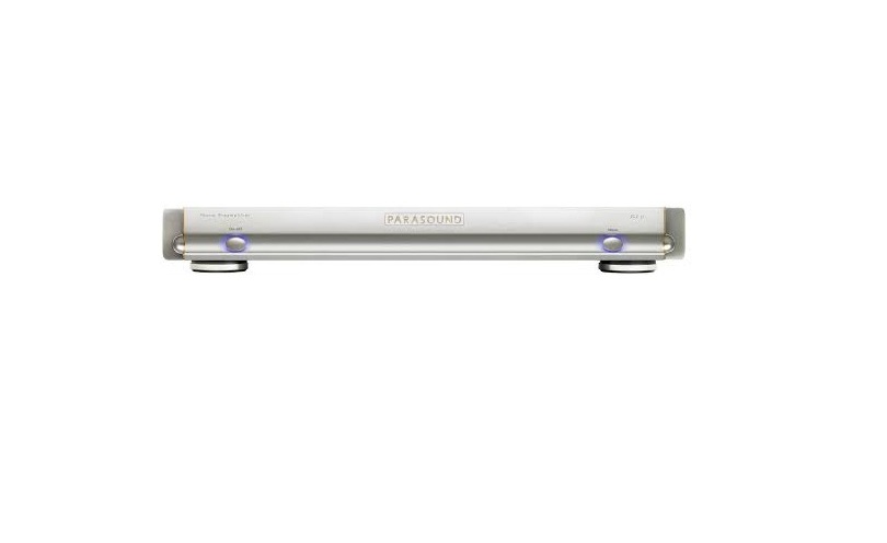
Thank You for Choosing ParasoundYour new Parasound Halo JC 3 Jr. Phono Preamplifier is the pinnacle of analog audio technology and value engineering. Its ” DNA” and circuit topologies are inspired by our acclaimed JC 3 and JC 3+. The JC 3 Jr. advances legendary designer John Curl’s reputation for designing legendary phono preamplifiers dating back to the 1970s. We are proud to offer you this exceptionally versatile audio component, confident that it will bring you many years of enjoyment and dependability. We appreciate you taking the time to read these instructions and thank you for selecting Parasound. For updates and corrections to this manual, we invite you to check our web site, www.parasound.com. Enjoy.The Parasound StaffKeeping Records for Future ReferenceRecord the serial number located on the back panel or bottom of your JC 3 Jr. in the space below. Also note your Parasound Dealer’s name and telephone number. Your purchase receipt/bill of sale is required to determine if your JC 3 Jr. is eligible for Parasound warranty service. We recommend that you make an extra copy of your original purchase receipt/bill of sale and store it inside the JC 3 Jr.’s carton. Five Digit Serial Number (located on the bottom) __________Date of Purchase: ____________Name of Parasound dealer where you purchased it ___________________Parasound Dealer Phone Number _______________________Important Warranty informationThere is no Parasound warranty for this unit if it was not purchased from an Authorized Parasound Dealer. Investigate warranty coverage statements made by an unauthorized dealer with extreme caution, as you will need to depend entirely upon your dealer, and NOT upon Parasound. Unauthorized dealers lack the capability to make repairs or arrange for repairs of Parasound equipment. A list of Authorized Parasound Dealers and detailed warranty information is available at www.parasound.com or you can call (415) – 397 – 7100 between 8:30 am and 4 pm Pacific time. A missing or altered serial number could indicate that this unit was re-sold by an unauthorized dealer or is stolen merchandise. If this unit is missing its serial number or the serial number has been altered, you should return it to your dealer immediately for a full refund.
Unpacking Your JC 3 Jr. & Placement Guidelines
Unpacking Your JC 3 Jr.Carefully remove your JC 3 Jr. from its shipping carton and locate all the enclosed accessories:
- AC power cord
- 12 V auto turn on trigger wire with a mono 3.5 mm (1/8″) mini plug at each end
While you are unpacking your JC 3 Jr. inspect it thoroughly for possible shipping damage and tell your Parasound dealer immediately if you find any. If possible, save and store both the inner and outer cartons andmost especiallythe foam packing inserts, to protect the JC 3 Jr. if you have to move it or ship it. You may wish to flatten the cardboard cartons to save room in storage after cutting the taped seams on the bottom flaps. This would be a good time to make a copy of your sales receipt to store with the JC 3 Jr.’s original packing.Placement GuidelinesThe JC 3 Jr. will be easier to use and will last longer if you follow these simple guidelines:
- Place the JC 3 Jr. on a shelf that will adequately support its weight.
- Use input and output cables that are long enough to leave some slack; that will enable. You to pull the JC 3 Jr. out of a cabinet to check or to change connections without inadvertently disconnecting cables.
- If you’re putting the JC 3 Jr. in a cabinet, it needs a space that’s at least 22 inches wide so you’ll be able to turn it around for access to its rear panel connections.
- Place your JC 3 Jr. where you can route input and output signal cables as far as possible from any AC cords.
- Where signal cables must cross AC cords they should do so only at a 90° right angle.
Ventilation Requirements
- Always position the JC 3 Jr. horizontally.
- We recommend that you do not place the JC 3 Jr. above a power amplifier or any other component which uses a large power transformer.
- Do not install the JC 3 Jr. in an unventilated equipment cabinet or compartment. Pockets of stagnant hot air can build up even in a cabinet with an open front and back.
Rack Mounting Your Parasound JC 3 Jr.Parasound does not manufacture a rack mount kit for the JC 3 Jr. With its four feet removed, the JC 3 Jr.’s panel height occupies 1-3/4″ or 44.5 mm, one rack space (“1U”): Mounting shelves for 1U equipment are made by a number of different companies.
AC Voltage Selection
115 V / 230 V AC Voltage Selector SwitchThis switch is found on the underside of the chassis. Make sure the 115 V/230 V switch is set for the correct AC line (mains) voltage before you plug in the JC 3 Jr.’s AC power cord. Note: The JC 3 Jr. could be seriously damaged if the AC Voltage Selector switch is in the wrong position for your voltage!Prior to plugging your JC 3 Jr. into an AC power source, check the position of the 115v/230v switch on the JC 3 Jr.’s chassis bottom and do not depend on the 115 V or 230 V markings on the carton.The 115 V setting is correct for North America where the JC 3 Jr. can operate safely with AC line voltages between 110 V-120 V. Most other countries will require the switch to be set to 230 V. With the 230 V setting the JC 3 Jr. can operate safely with AC line voltages between 220 V-240 V. Always turn off your JC 3 Jr. and disconnect its AC cord before making or changing the input, audio output or trigger wire connections. Inserting or removing an input or output cable while the JC 3 Jr. and your line stage preamp and power amplifier are turned on can result in a blast of sound that can damage your loudspeakers. Make sure there is no strain or tension on any cables that could cause them to pull loose.
Connecting & Adjusting your JC 3 Jr.
Always disconnect the AC cords to your JC 3 Jr. and integrated amplifiers or power amplifier before making or changing the input, output or trigger wire connections. Inserting or removing an audio input or output interconnect while the JC 3 Jr., integrated or power amplifier is turned on can result in a blast of sound that can damage your loudspeakers. Make sure there is no strain or tension on any cables that could cause them to pull loose while these are turned on.
 Audio Input Connection & Settings
 Audio Input Connection & Settings
Connect your turntable’s signal cables to the Input jacks on the JC 3 Jr. It is a good idea to treat the turntable cable’s RCA plugs with Deoxit (http://www.deoxit.com/) to remove any oxidation on them. The turntable’s ground wire attaches to the JC 3 Jr. Ground terminal that is located next to the right channel XLR balanced output.Note: In some cases eliminating hum might require connecting your turntable ground wire directly to your line stage preamp instead of to the JC 3 Jr. You can use a chassis screw or the outer ring of an RCA connector on your line stage. In rare instances hum might be lowest if your turntable ground wire is not attached at all.Important Note: Turntables and phono preamps are very sensitive to electromagnetic fields that can cause audible hum. To minimize hum follow these guidelines:
- Place your turntable as far as possible from amplifiers and AC power line conditioners.
- Run your turntable signal cables as far as possible from power amplifiers and AC power line conditioners.
- Do not run the turntable signal cables parallel with any AC cords.
- Wherever turntable signal cords must cross AC wires they should cross at a 90o right angle.
- It might be necessary for you to experiment with the exact positioning of the turntable signal cables to minimize hum.
JC 3 Jr. Input Settings
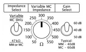 Cartridge Impedance Select SwitchSelect the setting that matches your turntable’s cartridge type. If you are unsure which setting is best for your equipment you might want to check it on the cartridge manufacturer’s website. You can also experiment with another setting which sounds the best in your system.The two position Impedance Select switch selects MC or MM cartridges. Select 47k
![]() input for all MM or certain MI (moving iron) cartridges. The MC Variable position works with the adjacent knob for adjusting the input impedance from 50-550 ohms.MM or MC – 47k
input for all MM or certain MI (moving iron) cartridges. The MC Variable position works with the adjacent knob for adjusting the input impedance from 50-550 ohms.MM or MC – 47k![]()
- For moving magnet or (rarely) moving coil cartridges.MC Variable Impedance
- Accommodates the vast majority of moving coil cartridges. This setting works in conjunction with the adjacent Variable MC Impedance Adjust control. Details are below.
Adjusting the Input Impedance Control (50-550![]() )The JC 3 Jr.’s Impedance adjust knob enables you to fine tune the input impedance for MC cartridges over a range of 50 ohms to 550 ohms. Cartridge manufacturers recommend what they consider to be an optimal load impedance. However, their spec won’t necessarily give you the best results in your system. We encourage you to experiment with this control and use whichever load impedance you feel results in the best performance of your system in your listening room. For some JC 3 Jr. users the sonic differences will be subtle.Gain ControlBefore listening to the JC 3 Jr. you should select the appropriate gain for your cartridge.40 dB
)The JC 3 Jr.’s Impedance adjust knob enables you to fine tune the input impedance for MC cartridges over a range of 50 ohms to 550 ohms. Cartridge manufacturers recommend what they consider to be an optimal load impedance. However, their spec won’t necessarily give you the best results in your system. We encourage you to experiment with this control and use whichever load impedance you feel results in the best performance of your system in your listening room. For some JC 3 Jr. users the sonic differences will be subtle.Gain ControlBefore listening to the JC 3 Jr. you should select the appropriate gain for your cartridge.40 dB
- The lowest gain settings. Typically used with moving magnet cartridges.
- 50 dBFor high output moving coil cartridges or low output moving magnet cartridges.
- 60 dBFor low output moving coil cartridges whose output is typically less than 0.5 mV. Whether you have an MC or MM cartridge you can experiment with which of the three gain settings gives you the best with your line stage preamp or integrated amplifier.
Audio Output Connections
The JC 3 Jr. Output jacks connect to the line level input jacks on your line level preamplifier or integrated amplifier. Each channel has one balanced XLR jack and one unbalanced RCA output jack. If your line stage preamplifier or integrated amp is equipped with balanced XLR inputs we recommend using the JC 3 Jr. Balanced XLR output jacks for the maximum rejection of external noise sources. The balanced and unbalanced jacks are active simultaneously.
Auto Turn On Option
Turn On Options switchThis switch enables you to choose whether your JC 3 Jr. is turned on and off manually or automatically, provided your preamp/line stage or integrated amp is equipped with a 12V trigger output jack.Note: Setting the Turn On Options switch to 12V disables the JC 3 Jr.’s front panel On-Off button.12 V In Jack for Auto Turn OnWhen the JC 3 Jr. Turn On Options switch is set to 12 V the JC 3 Jr. will turn On and Off automatically with your preamplifier. The 12 V input is a 3.5mm (1/8″) mono mini jack. To trigger the JC 3 Jr. on and off automatically, insert the trigger wire plug into this jack and plug the other end into your preamplifier or integrated amp’s 12V output jack.Note: The JC 3 Jr. trigger circuit draws a negligible 10mA current from the triggering device.12 V Loop Out JackThe Trigger Out jack lets you loop or “daisy-chain” the incoming trigger voltage to another component.
AC Power Connections
AC Power Inlet & Power CordA high quality IEC-type AC power cord is supplied with your JC 3 Jr. Please connect it directly to an AC wall outlet or power line conditioner that is always “live.” If possible, plug your JC 3 Jr. into the same AC wall outlet or line conditioner that your line level preamplifier or integrated amp is plugged into. If a different AC outlet is used for the JC 3 Jr. the ground potential may be higher or lower between the AC outlets, resulting in audible hum.Rear Panel AC Power SwitchThis switch is provided to turn the JC 3 Jr. completely off when it will not be used for an extended time. Normally, this switch is left in the “on” position (upper section is pressed in).
Front Panel Controls
On-Off ButtonPush once to turn on the JC 3 Jr. The audio output is delayed for a few seconds as its circuits stabilize and the DC servos settle down. When the JC 3 Jr. is turned on the faint blue glow around the On-Off button will become brighter. Push again to turn off the JC 3 Jr.Note: The On-Off button is disabled when the Turn On Options switch (on the rear panel) is set to 12 V.Mono ButtonPress the Mono button one time to parallel the left and right stereo channels to mono. Press it a second time to return to stereo. The Mono button glows blue when stereo is selected and changes to amber when mono is selected. Older mono records and stereo records pressed with high levels of rumble will sound cleaner when you select mono on the JC 3 Jr.
Design Overview
John Curl’s phono preamp design are legendary. His skills for amplifying extremely low level signals gives you, the listener, the best possible opportunity to experience the full emotional content of vinyl. In the JC 3 Jr. the physical implementation of the circuits closely follows the actual circuit topology and the layout is as compact as possible to minimize pickup of external noise. The sensitive phono circuitry is isolated by a thick aluminum partition. This separates critical audio signals from the non-audio circuits and wiring. The JC 3 Jr. power supply uses a high capacity 1 ampere toroid power transformer. The transformer is encased (“potted”) in epoxy within a steel enclosure to further reduce any vibration or noise contamination. The JC 3 Jr. employs a common mode inductor to reduce noise from the AC power source from coming into the power supply board. The resulting extremely low noise levels enable musical nuances to emerge from an utterly silent background.
Frequently Asked Questions
Why won’t the JC 3 Jr. turn on when I press the On-Off button?– Check the setting of the Turn On Options switch. It must be set to Manual for the front panel On-Off button to function.Why won’t the JC 3 Jr. turn on with an external DC trigger?– Check the setting of the Turn On Options switch. It must be set to 12 V for the 12V trigger to function. Try reversing the polarity of your 12V trigger source.– Both trigger wire plugs must be mono (as supplied with the JC 3 Jr.)Why is there no sound from the speakers?– Check that the AC is live -Check that AC Power switch on the rear panel is pressed to its on position.– Check that the On-Off button and Mono button are illuminated.– Check that input and output cables are secure at both ends.I can hear a background hum or hiss from the speakers– Try a lower gain setting. Options are 40 dB, 50 dB and 60 dB).– Make sure that you have attached your turntable’s ground wire to the ground terminal on the back panel of the JC 3 Jr.– Move audio cables and AC cords away from each other. – Try to route audio cables and AC cords perpendicular to each other.– Ensure that the JC 3 Jr., line level preamp, power amp and integrated are plugged into the same wall AC outlet or power strip.-You might find that you need to attach the JC 3 Jr. Ground terminal to an audio ground on your line level preamplifier. Contact Parasound Technical Service for specific instructions.The sound is distorted and too loud– Try a lower gain setting (the options are 40 dB, 50 dB and 60 dB).– The most frequent reason for distortion is using an MM cartridge with the JC 3 Jr. Gain switch set to 50 dB or 60 dB (try 40 dB). The second most frequent reason is using a high-output MC cartridge with the Gain Switch set to 60 dB (try 50 dB). – The higher voltage of the XLR balanced outputs could overload the input stage of your line level preamp or integrated amp. Try using the RCA unbalanced outputs.The sound is faint– Try a higher gain setting (the options are 40 dB, 50 dB and 60 dB).– The most common cause is using an MC cartridge while the JC 3 Jr. Gain switch is set to 40 dB (try 50 dB). The second most frequent reason is using a low-output MC cartridge while the Gain Switch is set to 50 dB or 40 dB (try 60 dB).Should I use Balanced XLR or Unbalanced RCA connections?We generally recommend balanced connections if your line stage preamplifier or integrated amplifier has balanced XLR inputs. The JC 3 Jr.’s balanced outputs enable you to take full advantage of the inherent noise-rejection capability. Recording and broadcast studios use balanced connections exclusively because balanced interconnects have an inherent ability to reject external sources of noise and hum, even when components are far apart and connected by long cables. Many high-quality preamplifiers and integrated amplifiers include balanced input connections with XLR jacks for the same reasons. Many serious listeners prefer the sonic characteristics of balanced connections because a lower noise floor assures the greatest dynamic contrasts plus more defined and spacious soundstage.Note: Balanced XLR connections are 6 dB “hotter” because the balanced circuit carries twice the voltage. Audio is noticeably louder than with unbalanced connections.
Do You Need Support?
Warranty RepairCall your Parasound dealer first. If the dealer can’t help you with your problem we encourage you to call Parasound’s Technical Service Department at 415-397-7100, Monday – Friday, 8am- 4pm Pacific time. We can suggest other diagnostic tests you can easily perform. If we determine that your JC 3 Jr. should be returned to Parasound or an Authorized Parasound Warranty Center for inspection and possible servicing, we will provide the location of a warranty center near you or shipping instructions for the unit’s return to Parasound. Read your accompanying Parasound Limited Warranty carefully to understand the applicable rights and limitations. This section provides instructions for obtaining repairs, both for units covered under the Parasound Limited Warranty and for units or situations which are outside the Warranty.The JC 3 Jr. is not eligible for repair under the terms of the Parasound warranty if:
- The unit was not purchased from a Parasound Authorized Dealer.
- You do not have the original bill of sale or sales receipt from a Parasound Authorized Dealer.
- You are not the original owner. The Parasound warranty is not transferable.
- Unit’s serial number was removed, modified, or defaced.
- Unit shows evidence of abuse and/or misuse.
- Unit was modified in any way.
- A prior repair was attempted by an unauthorized repair station.
Before You Return Any Unit to Parasound for ServiceDo not ship your JC 3 Jr. to Parasound without a Return Authorization (RA) number provided by our technical department. Before you send your unit to Parasound, you will need to obtain a specific Return Authorization (RA) number and shipping instructions from Parasound’s Technical Department. The RA number must be clearly marked on the outer carton. Use the original factory packing materials and arrange adequate insurance to cover its replacement value. You must include a copy of your purchase receipt, since this document establishes the validity of this unit’s warranty. Warranty repairs are only performed by Parasound or Parasound Authorized warranty centers when your purchase receipt is from a Parasound Authorized Dealer or Parasound Authorized Reseller.Note: Please do not ship to Parasound by the USPS (US Postal Service) – we will not accept delivery. We will also refuse delivery of units whose cartons show evidence of damage caused by inadequate packing.
Specifications
| Frequency Response: | 20-20Khz, +/- 0.2dB |
| Total Harmonic Distortion | < 0.02% at 1kHz |
| Signal to Noise Ratio, 40 dB Setting | >85dB, input shorted, IHF A-weighted
>80dB, input shorted, unweighted |
| Signal to Noise Ratio, 50 dB Setting | >89dB, input shorted, IHF A-weighted
>84dB, input shorted unweighted |
| Signal to Noise Ratio, 60 dB Setting | > 94dB, input shorted, IHF A-weighted
> 91dB, input shorted, unweighted |
| Inter-channel Crosstalk | >80dB at 1kHz |
| Input Impedance | MM or MI: 47kΩ
MC Variable: 50- 550Ω |
| Output Impedance | Unbalanced:
< 100Ω Balanced: < 100Ω per leg |
| Input Sensitivity at 1 kHz, 4mV Input | 40 dB: 4 mV for 450mV output
50 dB: 4 mV for 1.4 Volts output 60 dB: 4 mV for 4.25 Volts output |
| Input Sensitivity at 1 kHz, 1V Output | 40 dB: 9 mV for 1.0 Volt output
50 dB: 3 mV for 1.0 Volt output 60 dB: 0.9 mV for 1.0 Volt output |
| Total Gain | 40 dB / 50 dB / 60 dB (unbalanced output)
46 dB / 56 dB / 66 dB (balanced output) |
| XLR Pin Identification | 1 = Ground (Shield)
2 = Positive 3 = Negative (Return) |
| AC Power Requirement | Standby: <1 watt
Power On: 9 watts 115VAC or 230 VAC 50 – 60Hz (Selected on rear panel) |
| Dimensions | Width: 17-1/4” (437mm)
Depth: 14-3/4” (375mm) Depth with cables: 17” (432mm) Height: 2-1/2” (63.5mm) Height, without feet: 1-3/4” (45mm) |
| Weight | Net: 13lbs. (5.9Kg)
Shipping: 19lbs. (8.6kg) |
| Specifications and features subject to change or improvement without notice. |
Parasound Products, Inc. 2250 McKinnon Ave, San Francisco,CA 94124 415-397-7100Fax 415-397-0144www.parasound.com
References
[xyz-ips snippet=”download-snippet”]