
Patterson Kelley P-K Storm Gas
Fired Boiler User Manual
Safety
General
P-K STORM ™ Boilers ST-2500, ST-3000, ST-3500, ST-4000 All P-K STORM ™ Gas-Fired Boilers must be:
- Installed, operated, and serviced in accordance with instructions contained in this manual and other supplemental manuals.
- Installed by qualified personnel in accordance with designs prepared by qualified facility engineers including: structural, mechanical, electrical, and other applicable disciplines.
- Operated and serviced in accordance with a comprehensive safety program determined and established by the customer. Do not attempt to operate or service until such a program has been established.
- Operated and serviced by experienced, qualified, and properly trained personnel in accordance with all applicable codes, laws, and regulations.
Safety Precautions
Provide a suitable location for the boiler, away from normal personnel traffic, with adequate working space, adequate clearances, proper ventilation and lighting, with a structure sufficiently strong and rigid to support the weight of the boiler, all piping, and accessories.
NOTICE !Each safety device must be maintained and checked per the recommended schedule. Refer to Maintenance.
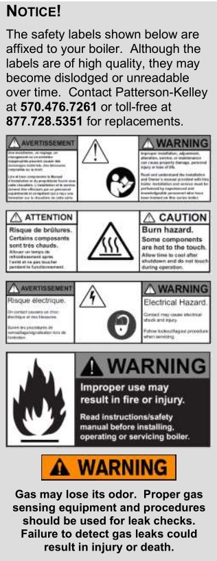
SAFETY F EATURESIt is the responsibility of the customer to ensure external safety provisions, such as but not limited to: guards, safety labels,safety controls, interlocks, lockout devices are in place and operable.
SAFETY LABELSThe following words are used in this manual to denote the degree of seriousness of the individual hazards.
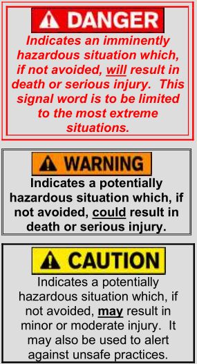
NOTICE /NOTE – NOTICEThe preferred signal word to address practices not related to personal injury. The safety alert symbol is not used with this signal word.
Training
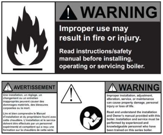
Proper training is the best protection against accidents. It is essential to read, understand, and follow the recommendations of this manual before installing, operating, or servicing this equipment. Failure to do so could result in fire or explosion and serious injury, death, and/or property damage.
Operating and service personnel must be thoroughly familiar with the basic construction of the P-K STORM ™ ST-2500, ST-3000, ST-3500 and ST-4000 boilers, the use and locations of the controls, the operation of the boilers, adjustment of their various mechanisms, and all applicable safety precautions. If any of the provisions of this manual are not fully and completely understood, contact Patterson-Kelley Technical Service at 570.476.7261 or toll free at 877.728.5351.
Hazard Warnings
Electrical Hazards
![]()
Shock Hazard! Properly Lockout/Tagout the electrical service and all other energy sources before working on or near the boiler.Shock Hazard! Do not spray water directly on this boiler or any electrical components.Electrical Hazard! Do not alter wiring connections.
Crush Hazards
![]()
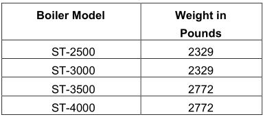
Lifting Hazards! Use properly rated lifting equipment to lift and position the boiler. The load is unbalanced. Test the balance before lifting off the floor. Do not allow personnel beneath the lifted load. Refer to the approximate weights in the table below
Bump Hazard from Overhead Ductwork and Piping
![]()
Injury Hazard! Install components with adequate vertical clearance.
Pressure Hazards
![]()
Pressure Hazard! Hot fluids. Install isolation valves on boiler water inlet and outlet. Make sure isolation valves are closed before servicing boiler.Pressure Hazard! Hot fluids. Annually test safety relief valve(s) for proper operation. Do not operate boiler with faulty relief valve(s).
Slip, Fall Hazards
![]()
Tripping Hazard! Do not install piping on floor surfaces. Maintain a clear path around the boiler.Slip and Fall Hazard! Use a drip pan to catch water while draining the boiler. Maintain dry floor surfaces.Slip and Fall Hazard! Do not locate intake or exhaust terminations above a walkway; dripping of condensate can cause icing of the walking surface. Refer to 2.5.5 for more information.Fall Hazard! Do not stand on boiler.
Chemical Hazards
![]()
Chemical Hazards from Cleaning Products. Use caution when cleaning the system. The use of professional assistance is recommended. Use safe procedures for the disposal of all cleaning solutions.Combustion Condensate – An acidic pH of approximately 3.0 to 5.0 can be expected. Use PVC, CPVC, or other corrosion resistant piping for drainage. Collection and disposal must be in accordance with all applicable regulations. A condensate neutralization kit is available. Please contact your local Patterson-Kelley representative for more information.
Burn, Fire and Explosion Hazards
![]()
Burn, fire, and explosion hazards! Installation must be in strict conformance to all applicable codes and standards including NFPA 54, ANSI Z223.1 and CAN/CSA B.149. Install all required vent lines for gas devices. Refer to 3.4 and 3.5 for more information.Hazard from Incorrect Fuels! Possible fire, explosion, overheating, and damage. Do not use any fuels except the design fuels for the unit.Overfire Hazards! High pressure in gas supply could result in overfiring of this or other devices supplied from the same source.

Fire and Explosion Hazards! Close the main gas shutoff before servicing boiler.Fire and Explosion Hazards! Do not store or use gasoline or other flammable vapors or liquids in the vicinity of this or any other gas fired appliance.Burn hazard! Possible hot surfaces. Do not touch gas vent during firing operation. Use only factory recommended vent components.Burn Hazard! Pipes, vents, and boiler components could be hot. Do not touch piping or stack surfaces during operation or immediately after shutdown of the boiler.Burn Hazard! Hot flue! Use caution when servicing or draining boiler.Fire and Explosion Hazards! Use caution when servicing burner. Propane (LPG) is heavier than air and may linger in the combustion chamber, vent lines, or elsewhere.Gas Leak Hazard! Make sure the burner is installed correctly and blower/transition is securely fastened following any maintenance performed on them. These connections may leak gas if assembled incorrectly.Gas Leak Hazard! All threaded gas connections must be made using a pipe compound that is resistant to liquefied petroleum gas. Do not use Teflon™ tape on threaded gas piping.Gas Leak Hazard! Check entire gas train for leaks after installation. If there is a smell of gas, shut down the boiler and obtain immediate assistance from trained service personnel and/or your local fire department.Overfire Hazard! Possible fire and explosion from excess gas pressure. Make sure that gas inlet pressure does not exceed 14 inches W.C.Overfire Hazard! Possible fire and explosion. Possible malfunction of regulators and/or gas safety shut off/control valves. Maintain all gas train components in good condition. Do not alter wiring connections.Annual inspection by factory-trained personnel for proper set-up and operation is recommended.Overfire and Underfire Hazards! Possible fire, explosion, overheating, and component failure. Do not attempt to adjust firing rate of the boiler. The firing rate must be adjusted only by factory trained personnel.
Introduction
This manual describes the installation and operation of the following P-K STORM ™ boilers featuring NURO ® controls.
ST-2500, ST-3000, ST-3500 & ST-4000:
- Natural Gas, 208-240V (three phase)
- Natural Gas, 440-480V (three phase)
NOTICE! This manual covers single fuel P-K STORM ® boilers (Natural Gas).
Individual differences between boiler models will be called out and defined in separate sections and the titles of these sections will include the boiler model number. If the boiler model numbers are not listed in the section title, that section is common to all boiler models.
If you have any questions on the information contained within, or do not fully and completely understand the content, please contact Patterson-Kelley Technical Service at 570.476.7261 or toll free at 877.728.5351.
The P-K STORM ™ gas-fired boiler is fully modulating using a variable speed combustion blower, sophisticated microprocessor controls, modulating gas safety shut off / control valves and a unique stainless steel heat exchanger capable of operating in a fully condensing mode to provide maximum efficiency in a minimum amount of space. The high-quality materials and design of the boiler should provide years of trouble-free service if the instructions in this manual are followed carefully.
The boiler is only a part of the complete heating system. This boiler may be fully operational but because of poor circulation, improper control, or other site related characteristics, not deliver heat to the desired location. Additional equipment such as temperature sensors, pumps, flow switches, balancing valves, and check valves will be required for satisfactory operation of any system. Patterson-Kelley cannot be responsible for the design or operation of such systems and a qualified engineer or contractor must be consulted.

Do not store or use gasoline or other flammable vapors and liquids in the vicinity of this or any other appliance.
If the information in this manual is not followed, fire or explosion may result causing property damage, personal injury, or loss of life.
Do not store or use gasoline or other flammable vapors or liquids in the vicinity of this or any other appliance. Installation and service must be performed by a qualified installer, service agency, or the gas supplier.
WHAT TO DO IF YOU SMELL GAS:
- Do not try to light any appliance.
- Do not touch any electrical switch; do not use any phone in your building.
- Immediately call your gas supplier from a neighbor’s phone. Follow the gas supplier’s instructions.
- If you cannot reach your gas supplier, call the fire department.
It is essential to read, understand, and follow the recommendations of this manual before installing, operating or servicing this equipment. Failure to do so could result in personal injury or death.
Installation and service must be performed by a qualified and knowledgeable individual who has been certified on the P-K STORM ™ boiler. The features which permit this boiler to achieve high-efficiency performance can be misused which could result in personal injury or death.
PRECAUTIONS ASSOCIATED WITH HANDLING REFRACTORY LINING MATERIAL
- This Patterson-Kelley product contains a Combustion Area lined with REFRACTORY CERAMIC FIBERS (RCFs) similar to many other devices produced in this industry.
- RCFs have been identified by the International Agency for Research on Cancer (IARC) as possibly being carcinogenic to Humans.
- AVOID breathing particles or dust from RCFs and avoid contact with Skin or Eyes.
- The National Institute for Occupational Safety and Health (NIOSH) recommends the use of a respirator meeting current standards, to avoid inhalation of dust. Also recommended is loose fitting, long sleeved clothing, eye protection and gloves whenever handling RCFs. Current NIOSH Recommendations are listed on their website at http://www.cdc.gov/niosh/homepage.html, which should be viewed before the handling or removal of Refractory Lining Materials on this or any similar device.
- Using a SPRAY BOTTLE, saturate with WATER; but not dripping, the combustion chamber lining to prevent dust from becoming airborne.
- Place removed RCFs into a plastic bag for disposal with normal trash.
- Wash exposed clothing (if not disposable), TWICE and DRY separately from other laundry.
Purpose of this Document
It is the purpose of this Installation and Owner’s Manual is to provide complete documentation support for P-K STORM ™ boilers featuring NURO controls. Patterson-Kelley is constantly seeking ways to produce high quality HVAC products. Our operation is based on the premium quality control program and insures that Patterson Kelley manufactures quality products.
The primary concern of all Patterson-Kelley equipment installation procedures is Safety. Safety instructions and considerations are presented and repeated throughout the document as needed. If you have any questions on the information contained within, or do not fully and completely understand the content, please contact Patterson-Kelley Technical Service at 570.476.7261 or toll free at 877.728.5351.
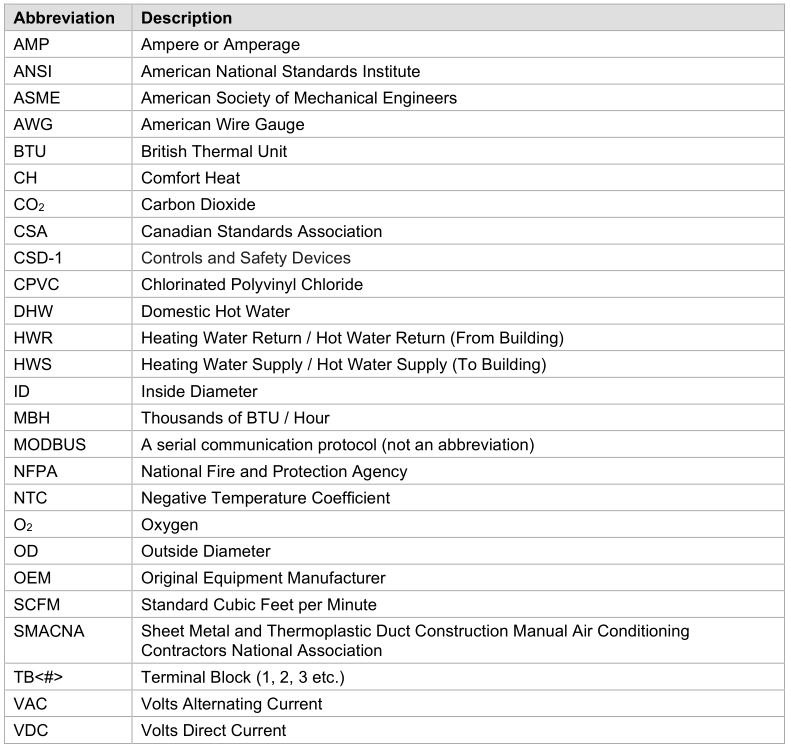
Common Abbreviations
Site Preparation
Installation and service must be performed by a qualified installer, service agency, or gas supplier. Failure to install the equipment in accordance with this manual could result in an unsafe operating condition.
NOTICE !Controls and other equipment that are damaged or fail due to weather exposure are not covered by warranty.
The boiler is heavy and requires additional technicians to support and move the unit(s) during installation. Use extreme caution to avoid dropping the boiler or cause any bodily injury while lifting or handling. When positioning this boiler, maintain positive control of it at all times. Do not attempt to move the boiler on surfaces that are not level. Failure to heed this warning could result in personal injury or death.
NOTICE !The boiler may be installed on a combustible floor; however, the boiler must never be installed on carpeting.
Bumping hazard from overhead ducts! Install all components with adequate vertical clearances. Insufficient clearance can restrict the service access, increasing the possibility of injury.
Initial Inspection upon Receiving
Upon receiving the boiler, inspect it for signs of shipping damage. Some damage may be hidden. Unpack the boiler, open the front and side doors and inspect the boiler. Verify that the total number of pieces shown on the packing slip agrees with those actually received.
NOTICE! Note any damage, suspected potential damage, or shortage of materials on the freight bill and immediately notify the carrier. File all claims for shortage or damage with the carrier. Claims for hidden damages must be filed with your carrier within 7 days. The carton is equipped with a “Tip (N) Tell”. If the “Tip (N) Tell” arrow point is blue, that indicates the package has been on its side or tipped over in transit.
Storage Prior to Installation
If the boiler is not installed immediately, it must be stored in a location adequately protected from the weather, preferablyindoors. If this is not possible, then it should remain in the shipping container and be covered by a tarpaulin or other waterproof covering.
NOTICE! Controls and other equipment that are damaged or fail due to weather exposure are not covered by warranty.
f the information in these instructions are not followed exactly, a fire or explosion may result causing property damage, personal injury, or death.
Should overheating occur or the gas supply fail to shut off, do not turn off or disconnect the electrical supply to the pump. Instead, shut off the gas supply at a location external to the appliance.
Compliance with Codes
Each P-K STORM ™ boiler with standard components complies with American National Standard/CSA Standard ANSI Z21.13/CSA 4.9, latest edition for Gas-Fired Low Pressure Steam and Hot Water Boilers.
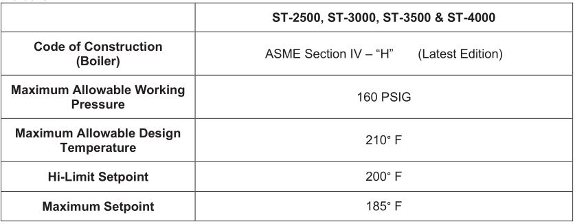
The P-K STORM ™ ST-2500, ST-3000, ST-3500 and ST-4000 heat exchangers are constructed and stamped in accordance with ASME Boiler and Pressure Vessel Code, Section IV for 160 psig maximum pressure and 210°F maximum temperature. Other codes or approvals which apply will be labeled on the boiler.
Installation of the boiler must conform to all the requirements of all national, state and local codes established by the authorities having jurisdiction or, in the absence of such requirements, to the National Fuel Gas Code, ANSI Z223.1/NFPA 54 latest edition in the U.S. In Canada, the equipment shall be installed in accordance with the current Installation Code for Gas Burning Appliances and Equipment, CAN/CSA-B.149, latest edition, and applicable Provincial Regulations for the class, which should be carefully followed in all cases. Authorities having jurisdiction should be consulted before making any installation.
Where required by local codes, the installation must conform to American Society of Mechanical Engineers Safety Code for Controls and Safety Devices for Automatically Fired Boilers (ASME CSD-1).
In the Commonwealth of Massachusetts (a) this unit must be installed by a licensed pipe fitter/plumber, (b) field installed gas cocks must be “T” handle type, (c) piping of condensate shall conform to the State Plumbing Code, and (d) refer to the Massachusetts Supplement for further details.
Location Setup
Foundation
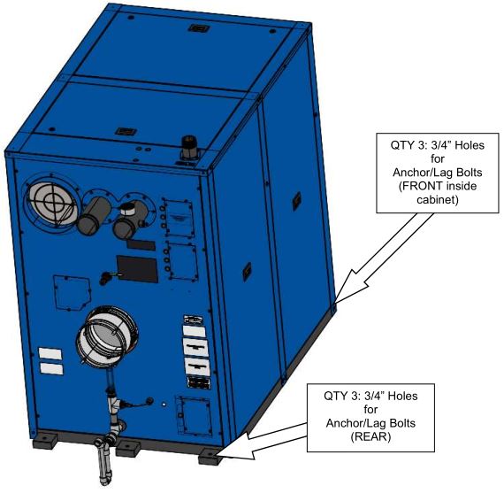
The appliance must be installed level, on a housekeeping pad, to function properly. Ensure the base is securely connected to the appliance. Use a bubble level and make sure housekeeping pad is level before installation of appliance. There are six 3/4” holes in the base which may be used for 5/8” anchor bolts. Three of these are located inside the cabinet and the other three are outside. The housekeeping pad is recommended to be 4 inches but no less than 1 inch in height.
NOTICE! The appliance may be installed on a combustible floor; however, the appliance must NEVER be installed on carpeting.
Clearances
If the boiler is to be installed near combustible surfaces, the minimum clearances are shown in the illustration below. Failure to provide adequate service clearances, even with non-combustible surfaces, may present problems during routine maintenance of the boiler. Maintain a clearance from the vent to combustible surfaces of 18” or as specified in the vent manufacturer’s listed installation instructions. The boiler must be installed in a space large in comparison to the boiler as described in the National Fuel Gas Code, NFPA 54/ANSI Z223.1, Latest Edition.
![]()
Note: Failure to provide recommended service clearances may make it difficult to perform service on the boiler(s).
Inlet Air and Exhaust Venting Considerations
Design and installation of venting systems should be done only by qualified and knowledgeable venting systems personnel and in accordance with vent system manufacturer’s installation instructions. Installing a boiler or vent system using improperinstallation methods or materials can result in serious injury or death due to fire or asphyxiation.
Before connecting a boiler to a venting system, it must be determined whether the boiler is to be installed in a conventional or direct vent configuration. In the US, provisions for combustion air must be in accordance with NFPA 54/ANSI Z223.1, National Fuel Gas Code, latest edition, or applicable provisions of local building codes. In Canada, combustion and ventilation air openings shall comply with CAN/CSA B-149.1 Natural Gas and Propane Installation Code.
For correct installation of a vent system, read all of these instructions and refer to the vent manufacturer’s instructions.
Failure to use a proper vent system (types and materials), as described in this manual will void the boiler warranty and may result in rapid deterioration of the venting system, creating a health or life safety hazard. Faulty vent installation can allow toxic fumes to be released into living areas. This may cause property damage, injury, or death.
Applicable Codes and Standards
United States Installation Codes:
NBIC – Part I __________________ National Board Inspection Code – InstallationNFPA 54/ANSI Z223.1 ___________National Fuel Gas CodeNFPA/ANSI 211 ________________Chimneys, Fireplaces, Vents and Solid Fuel Burning Appliances
Canada Installation Codes:
CAN/CSA B149.1________________Installation Codes for Gas Burning Equipment
Flue Gas Exhaust Vent Standards:
UL 441 / ULC S605 ___________ Standard for Gas VentsUL 1738 _____________ Venting Systems for Gas-Burning Appliances, Categories II, III and IVULC S636-95_____________ Standard for Type BH Venting System Sheet Metal and Thermoplastic Duct Construction Manual Air Conditioning Contractors National Association (SMACNA)
These codes and standards contain information for the venting of gas fired appliances, including, but not limited to vent sizing, location, clearance to combustibles, and safe installation practices. The installation must comply with both the above Federal Codes and with state, provincial, and local codes.
Combustion Air Inlet Planning (United States and Canada Considerations)
- Air inlet requirements for the U.S. are established by NFPA 54/ANSI Z223.1 & NFPA/ANSI 211.
- Air inlet requirements for Canada are established by CAN/CSA B149.1.
Refer to see section 3.4, for more details on combustion air inlet requirements in the United States and Canada.
Category II/IV Flue Gas Exhaust Vent Planning
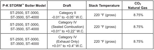
Several codes and standards have categorized appliances in accordance with the flue gas temperature and pressure produced by the appliance. The applicable categories are defined as follows:
- Category II: An appliance that operates with a non-positive vent static pressure and with a vent temperature that may cause excessive condensate production in the vent.
- Category IV: An appliance that operates with a positive vent static pressure and with a vent temperature that may cause excessive condensate production in the vent.
- Direct Vent: An appliance that is constructed and installed so that all air for combustion is derived directly from outdoors and all flue gases are discharged to the outdoors.
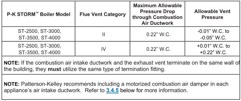
All P-K STORM ™ boilers are dual-certified as Category II or IV appliances, as defined in ANSI Z21.13/CSA 4.9, latest edition. The P-K STORM ™ series boilers are capable of operating with slightly negative to slightly positive exhaust pressure. It is critical to ensure the flue vent material is certified for Category II or IV operation.
NOTE : For Category II installations, ensure the flue venting system is designed to maintain a slightly negative exhaust pressure between -0.01” W.C. and -0.05” W.C.
NOTE : For Category IV installations, ensure the flue venting system is designed to maintain a slightly positive exhaust pressure which MUST BE in the following ranges:
- +0.01” W.C. and +0.22” W.C. (Direct Vent / Sealed Combustion)
- +0.01” W.C. and +0.4” W.C. (Exhaust Only)
The vent material to be used for US and Canada is listed in the Table of Acceptable Materials for Venting Systems located in 2.5.4.
Vent installations shall be in accordance with NFPA 54/ANSI Z223.1, the National Fuel Gas Code, or CAN/CSA-B149.1, the Natural Gas and Propane Installation Code, or applicable provisions of the local building codes.
Vent Sizing for Category II / IV OperationThe vent must be sized in accordance with the ASHRAE Systems and Equipment handbook (Chapter 30) or according to the vent manufacturer’s recommendations. When using manufactured venting systems, consult your vent supplier for correct sizing and structural support requirements.
Venting Materials for Flue/Exhaust Systems
The P-K STORM boilers are dual certified as a Category II and Category IV appliances, which vents with a temperature that is likely to cause condensation in the vent. Therefore, any venting system used with the P-K STORM ™ boiler must comply with the requirements for either Category II or Category IV venting systems as specified in the latest edition of NFPA 54/ANSI Z223.1 in the US or the latest edition of CAN/CSA B-149.1 in Canada.
CPVC VentingUS: CPVC pipe conforming to ASTM F441. Sch. 80 fittings conforming to ASTM F439. Joints are to be sealed with solvent conforming ASTM 493.Canada: CPVC Pipe, Fitting and Sealant listed and labeled to ULC S-636 Standard for Type BH Venting Systems.
Polypropylene VentingUS and Canada: Polypropylene such as InnoFlue ® from Centrotherm or PolyPro ® from DuraVent or Z-DENS from Z-Flex ® or other listed manufacturers. When used, the same manufacturer’s material must be used throughout the system. It is not permissible to use material from different manufacturers within the same system.
As per ANSI Z21.13b * CSA 4.9b:
- The use of cellular core PVC, cellular core CPVC, or Radel ® as venting materials is prohibited.
- The use of external insulation on plastic vent pipe is prohibited.
Acceptable Venting Materials
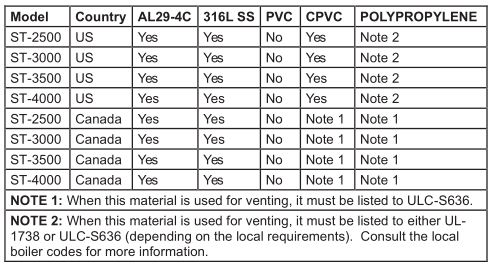
The venting materials listed are intended for the venting of gas burning appliances only. Do not use these venting materialsfor venting liquid or solid fuel (such as oil, kerosene, wood, or coal) appliances.
Maintain clearances to combustibles as listed in the vent manufacturer’s installation instructions or as set forth in the codes and standards listed in this section.
Do not use these vent pipes for incinerators of any sort!
This boiler is not certified for use with PVC venting. Use of PVC venting may result in vent failure and possible serious injury or death.
Required Clearances
Conventional Vent Systems ClearancesThe following termination clearance requirements are for conventional non-direct vent installations:
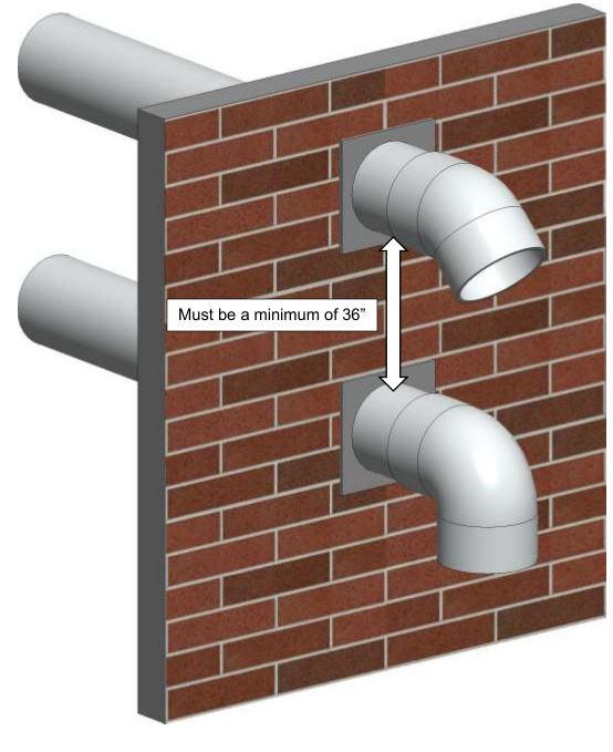
- The vent system shall terminate at least 3 ft. above a forced air inlet located within 10 ft. horizontally.
- The vent system shall terminate at least 4 ft. below, 4 ft. horizontally from, or 1 ft. above any door, operable window or gravity inlet into any building. The bottom of the vent terminal shall be at least 12 in. above grade or highest expected snow line (if applicable).
- Through the wall terminations shall not terminate over public walkways or over an area where condensate or vapor could create a nuisance or hazard or could be detrimental to the operation of regulators, relief valves, or other equipment.
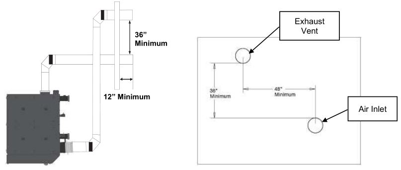
Direct Vent (Sealed Combustion) Systems Clearances
- The vent terminal shall be located at least 12 in. from any air opening into a building. The bottom of the vent terminal shall be at least 12 in. above grade. Both the vent and air intake terminals must be at least 12 in. above the highest expected snow line.
- Through the wall terminations shall not terminate over public walkways or over an area where condensate or vapor could create a nuisance or hazard or could be detrimental to the operation of regulators, relief valves, or other equipment.
- When multiple direct vent appliances are adjacent, the exhaust must terminate at least 10 ft. horizontally or 3 ft. vertically from the air intake of another appliance.
![]()
The boiler vent should not be connected into any portion of another mechanical draft system without consulting the ventmanufacturer. The boiler shall not be connected to any part of a vent system serving a Category I appliance, nor shall a Category I appliance be connected to any part of the vent system serving this appliance. For Category II common venting, refer to local venting codes. Improper interconnection of venting systems may result in leakage of flue gases into occupied spaces.
![]()
Interior Component Clearances
All vent system components shall be installed so as to maintain the following minimum clearances:
![]()
Flue ConnectionThe connection from the appliance to the vent should be as direct as possible and the upward slope of any horizontal breaching should be at least 1/4 inch per linear foot. Examples of the complete exhaust system with drain is in 3.5. The appliance connector should incorporate provisions to drain condensate formed in the vent system. The connector should include an appropriate drain section (not provided).
Gas Piping Considerations
Before making the gas hook-up, make sure the boiler is being supplied with the type of fuel shown on the boiler nameplate.
Supplying a fuel other than that shown on the appliance’s nameplate can lead to over firing of the appliance. This cancause damage to the equipment which could result in serious injury and/or death.
The boiler shall be installed such that gas ignition system components are protected from water (dripping, spraying, rain, etc.) during appliance operation and service (circulator replacement, control adjustment, etc.).
Water Quality Standard
The P-K STORM ™ boiler’s heat exchanger is made of stainless steel. The heat exchanger requires proper water conditions to remain efficient and function properly. For more information, refer to Patterson-Kelley’s Water Quality Standards for Hydronic Boilers in Multi-Metal Systems in Appendix C– Water Quality Standards Quality Standards for Hydronic Boilers in Multi-Metal Systems, as this applies to the warranty of your heat exchanger.
NOTE: Failure to maintain the water quality according to the requirements of the multi-metal systems water quality standards can void the heat exchanger warranty.
Installation
Overview
For site preparation follow the guidelines established in Section 2. Section 3 details the installation requirements for electrical connections, combustion air, and flue vent piping, hydronic piping, etc.
Appliance Connections
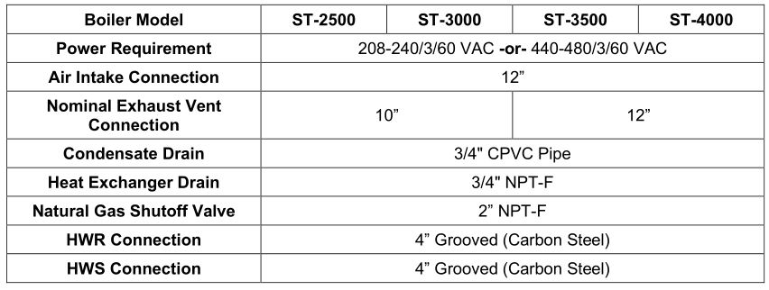
The table below summarizes the appliance connections to the P-K STORM ™ series boilers:
Appliance Connections (ST-2500 & ST-3000)
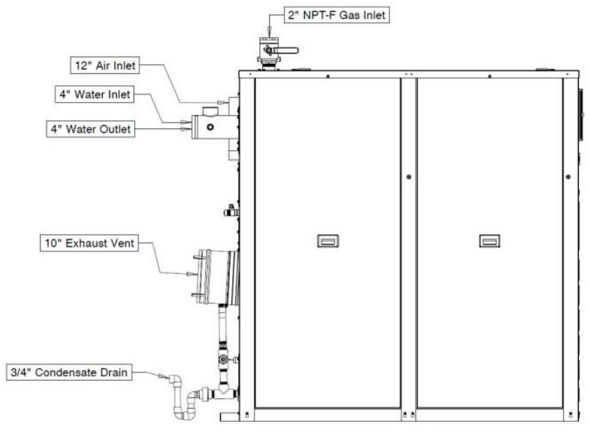
All connections must be in compliance with national, state, and local code requirements.
Appliance Connections (ST-3500 & ST-4000)
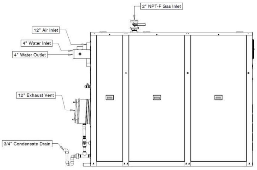
All connections must be in compliance with national, state, and local code requirements.
Electrical Connections
Power Requirements
The STORM boilers can be manufactured for 208-240 VAC, three phase, 60 hertz electrical service OR 440-480VAC, three phase, 60 hertz electrical service. The total operating amperage is indicated on the rating nameplate require less than 20 Amps at full load. Before starting the boiler, check to ensure that the proper electrical service is connected to the boiler.
An external electrical disconnect and overload protection (not supplied with the boiler) are required.
NOTE: The STORM boilers MUST be ordered to the correct voltage! IT IS NOT POSSIBLE to convert the boiler between the 240V and 480V configurations in the field!
Refer to Section 6.2, for proper wiring and configuration of the electrical connections. The electrical service to the boiler must be installed and grounded in accordance with local codes or in the absence of such requirements, in the U.S. with National Electrical Codes, ANSI/NFPA No. 70 latest edition or, in Canada, to the current Canadian Electrical Code, Part I, CSA C22.1 latest edition. Installed conduit must not block any of the boiler’s openings and must allow the front door to be opened.
Three Phase Power Supply Connection
Main Power Connection BoxAlways check the rating nameplate of the Storm boiler to determine the required electrical service:
- 208-240VAC, three phase, 60 hertz
- 440-480VAC, three phase, 60 hertz
The incoming three phase power for the ST-2500-ST-4000 boilers is connected to the over-current safety device (rated for 20 Amps) and the Ground terminal located in the main power connection box. The image on the next page shows the Low Voltage (TB1) and High Voltage (TB2) terminal blocks, plus the Main Power Connection Box on the ST-2500-ST-4000.
- Terminal 1 = HOT L1
- Terminal 3 = HOT L2
- Terminal 5 = HOT L3
- Terminal G = GROUND
Control TransformerThe Main Power Connection Box features a Control Transformer which steps down two hot leads from the incoming three-phase power in order to supply 110-120VAC single phase power to the NURO ® control system. Be aware that Storm boilers ordered in the 240V configuration, are pre-wired from the factory for operation with 240 VAC three phase incoming power.
NOTICE: If 208 VAC three phase power is supplied to the boiler, the internal control transformer must be re-wired for operation at this lower voltage. The wire in terminal X3 on the load side of the internal control transformer must be moved to terminal X4. This supplies 110 VAC power to the NURO ® control from the 208 VAC main voltage. Refer to Section 7.2.4 for proper wiring and configuration of the internal control transformer.
![]()

Do not over-tighten the hot lead terminal screws. Maximum tightening torque = 13 in-lbs!
NOTE: The hot lead terminals can accommodate maximum 12AWG wire. The ground terminal can accommodate maximum 8AWG wire.
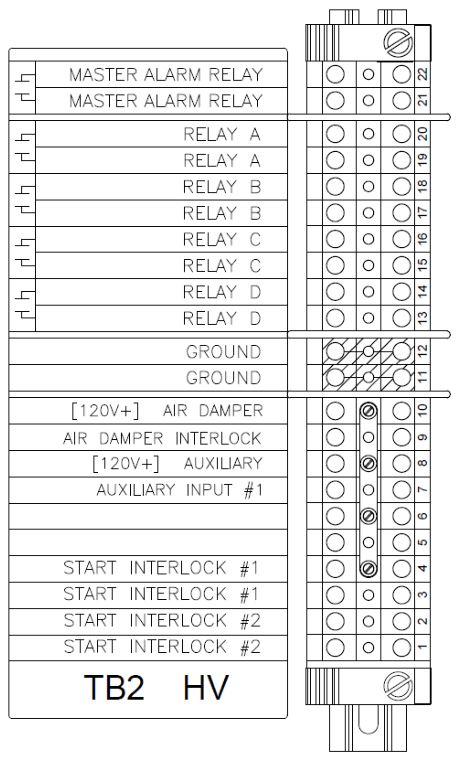
High Voltage (TB2) Terminal Block
Be sure to check the nameplate on the boiler before connecting the electrical supply.
NOTICE !A dedicated earth ground (green wire) is required to avoid nuisance shutdowns. Do not ground through the conduit!

The high voltage (TB2) terminal block on the Storm boilers with NURO controls contains dry-contact relays with a maximum voltage rating of 240VAC and 1/2 Amp maximum current capacity. Incorrect wiring can result in equipment damage, injury, or death.
Start Interlock #2 – The Start Interlock #2 TB2-1 and TB2-2 terminals are in series with Start Interlock #1 and provide additional connection points for auxiliary safety devices. This circuit is energized with 120VAC, so the contacts on any auxiliary safety devices must be rated for minimum 120VAC.
Start Interlock #1 – The Start Interlock #1 TB2-3 & TB2-4 terminals can be used for auxiliary safety devices such as damper limit switches, control valve limit switches, emergency stop buttons, and low water cutoff devices. This circuit is energized with 120VAC, so the contacts on any auxiliary safety devices must be rated for a minimum of 120VAC. The appliance ships with a factory-installed jumper across Start Interlock #1 and Start Interlock #2 terminals. Remove the jumper(s) if using any auxiliary safety devices.
NOTE: The Start Interlock circuit must close within 5 minutes of a call for heat. Failure to close the Start Interlock circuit will cause the appliance to lockout on alarm.
Auxiliary Input #1 – The TB2-7 & TB2-8 terminals are reserved for future use. This circuit is energized with 120VAC.
Air Damper Interlock – The Air Damper Interlock TB2-9 & TB2-10 terminals allow for proof of open end limit switch on a motorized air damper. This circuit is energized with 120VAC, so the contacts on the end limit switch must be rated for minimum 120VAC. The appliance ships with a factory-installed jumper across the Air Damper Interlock terminals. Remove the jumper if connecting a motorized air damper with end limit switch.
NOTE: The boiler ships with a factory-installed jumper across the Air Damper Interlock terminals. Remove the jumper if connecting a motorized air damper with end limit switch.
Ground – Grounding connection for auxiliary safety/limit devices on terminals TB2-11 & TB2-12.
NOTE: This ground terminal is connected to the TB2 sheet metal and is not common with the appliance’s electrical service ground.
Relay A, B, C & D – User-configurable relay outputs A (TB2-19 & TB2-20), B (TB2-17 & TB2-18), C (TB2-15 & TB2-16) & D (TB2-13 & TB2-14). The normally-open contacts on these relays have a maximum voltage rating of 240VAC and maximum current capacity of 1/2 Amp.
NOTE: Refer to 6.1 or proper wiring and configuration of the electrical connections. Relays A through D can be user-configured through the NURO ® touch screen interface to control devices such as the Comfort Heat (CH) pump, Domestic Hot Water (DHW) Pump, Air Damper, System Pump, etc.
Master Alarm Relay – The Master Alarm Relay TB2-21 & TB2-22 terminals are normally-open dry contacts that close in the event of an alarm output from the NURO control. The normally-open contacts on this relay have a maximum voltage rating of 240VAC and maximum current capacity of 1/2 Amp.
Low Voltage (TB1) Terminal Block
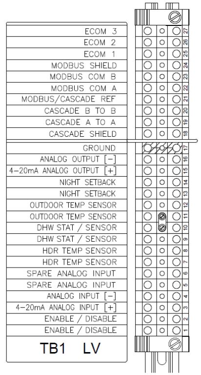
Enable/Disable –TB1-1 and TB1-2 can be used to remotely enable or disable the boiler. The functionality of these terminals is user-configurable through the NURO ® controls, but generally closure of the Enable/Disable circuit provides a call for heat to the boiler. Opening this circuit prevents the boiler from running.
NOTE: The boiler ships with a factory-installed jumper across the Enable/Disable terminals. This circuit is energized with a 24VAC potential, so the contacts on any remote enable devices must be rated for minimum 24VAC.
4-20mA Analog Input – TB1-3 and TB1-4 can be used to provide a remote analog 4-20mA control signal to the boiler. This analog signal can be used to change the boiler’s operating setpoint/firing rate.
Spare Analog Input – TB1-5 and TB1-6 are reserved for future use.
HDR Temp Sensor – TB1-7 and TB1-8 can be used to connect a remote header temperature sensor, installed in the primary hydronic system piping, downstream of all the boilers. This temperature sensor must be a 2-wire 12kΩ NTC thermistor. This circuit is energized by the boiler with a 5VDC potential.
DHW Stat/Sensor – TB1-9 and TB1-10 can be used to connect either an aquastat or remote DHW temperature sensor installed in a domestic hot water storage tank. If using an aquastat, use a SPST normally-closed, break on rise type with either a fixed or adjustable deadband above and below the setpoint. Alternatively, if using a temperature sensor, it must be a 2-wire 12kΩ NTC thermistor and be of sufficient length to measure an accurate storage tank temperature. This circuit is energized by the boiler with a 5VDC potential.
Outdoor Temp Sensor – TB1-11 and TB1-12 can be used to connect an outdoor air temperature sensor which allows the NURO control to be programmed to run an outdoor air schedule. The outdoor air temperature sensor must be a 2-wire 12kΩ NTC thermistor and should be installed on the North face of the building and shielded from direct sunlight exposure. This circuit is energized by the boiler with a 5VDC potential.
Night Setback – TB1-13 and TB1-14 can be used to connect a day/night or occupancy timer. Closure of the Night Setback circuit enables the Night Setback mode which reduces the boiler’s operating setpoint. Opening this circuit resumes normal operation. This circuit is energized by the boiler with a 5VDC potential, so the contacts on the day/night timer must be rated for minimum 5VDC.
4-20mA Analog Output – TB1-15 and TB1-16 provide a 4-20mA analog output signal which tracks the boiler’s firing rate. When operating at full power (maximum firing rate), the boiler will provide a 20mA output. When operating at minimum power (minimum firing rate), the boiler will provide a 4mA output.
Ground – TB1-17 provides an equipment (frame) ground connection for input, output, or communication connections. For independently powered control devices, it may be necessary to create a common ground.
Cascade Shield & Cascade – TB1-18, TB1-19, and TB1-20 can be used to setup a cascade system with multiple STORM boilers with NURO controls. Terminals TB1-19 and TB1-20 are reserved for the cascade communication between the master and member boilers. Terminal TB1-18 should be used to connect the cascade communication wiring shield between all boilers. The cascade and shielding must be wired from the master boiler to each individual member boiler in a daisy-chain fashion.
NOTE: Only ground the Cascade shield wire at the master boiler.
MODBUS COM & MODBUS Shield – TB1-22, TB1-23, and TB1-24 can be used to integrate the boiler with a Building Management System (BMS), Protocol Converter, or other device capable of RS-485 2- wire MODBUS communication. Terminals TB1-22 and TB1-23 are reserved for MODBUS and terminal TB1-18 provides a connection for the MODBUS communication wire shield.
NOTE: Only ground the MODBUS shield wire at the master boiler.
ECOM 1, 2 & 3 – TB1-25, TB1-26, and TB1-27 can be used to connect a wireless outdoor air temperature sensor. The wireless receiver should be installed at or near the boiler, and the wireless temperature sensor should be installed on the North face of the building and shielded from direct sunlight exposure.
Combustion Air
Air Inlet Requirements – United States
Air inlet requirements for the United States are established by NFPA 54/ANSI Z223.1 & NFPA/ANSI 211. When air is supplied from inside the building, the total required volume shall be the sum of the required volume for all the appliances located in the mechanical room. Adjacent rooms furnished with fixed openings communicating directly with the mechanical room are considered part of the required volume. The minimum volume is 50 ft 3 per 1,000 Btu/Hr (4.8 m 3 /kW) of installed appliance input capacity.
Openings used to connect indoor spaces to obtain the required minimum volume shall be sized as follows:
- When rooms are on the same floor, each opening shall have an area equal to 1 square inch for each 1,000 Btu/Hr (2,200 mm 2 /kW) of installed appliance input capacity, but not less than 100 square inches. One opening should commence less than 12 inches above the floor and the other less than 12 inches below the ceiling. The minimum dimension of air openings shall be 3 inches.
- When rooms are on different floors, each opening shall have an area equal to 2 square inches for each 1,000 Btu/Hr (4,400 mm 2 /kW) of installed appliance input capacity.
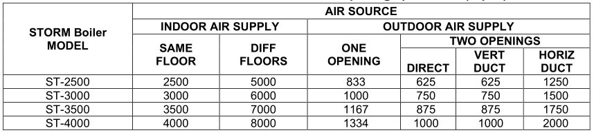
When combustion air is supplied from outside the building, the boiler room shall be provided with one or two openings to ensure adequate combustion air and proper ventilation.
Under no circumstances shall the boiler room ever be under a negative pressure. Particular care should be taken when exhaust fans, compressors, air-handling units, or other equipment may rob air from the boiler. Note that this equipment might be in rooms other than the boiler room. This applies to both sealed combustion and atmospheric room combustion air applications.
When using one permanent opening, the opening shall commence within 12 inches of the ceiling and shall communicate directly with the outdoors or through a vertical or horizontal duct that communicates to the outdoors. Minimum free area of the opening is 1 square inch for each 3,000 Btu/Hr (700 mm 2 /kW) of installed appliance input capacity, and not less than the sum of the areas of all vent connectors in the room.
When using two permanent openings, one opening shall commence within 12 inches above the floor and the other within 12 inches below the ceiling, preferably on opposite walls. The openings shall communicate directly, or by way of ducts, with free outdoor air. The minimum net free area of the openings shall be calculated in accordance with the following:
- When air is taken directly from outside the building, each opening (minimum of two, as outlined above), 1 square inch for each 4,000 Btu per hour (550 mm 2 /kW) of total boiler input is required.
- When air is taken from the outdoors through a vertical duct into the mechanical room, 1 square inch per 4,000 Btu per hour (550 mm 2 /kW) of total boiler input is required.
When air is taken from the outdoors through a horizontal duct into the mechanical room, 1 square inch per 2,000 Btu per hour (1,100 mm 2 /kW) of total boiler input is required.
United States Minimum Area of Ventilation Openings per Boiler (Sq. In)
NOTES:
- The required size of openings for combustion and ventilation air shall be based on the net free area of the opening.
- Screens shall not be smaller than 1/4 inch.
- Motorized louvers shall be interlocked with the appliance so that they are proven open prior to main burner ignition and operation.
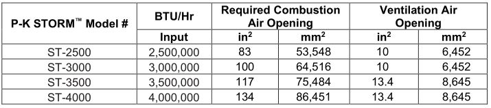
A. Ventilation of the space occupied by fuel burning appliance(s) or equipment shall be supplied by a ventilation opening at the highest practicable point communicating with the outdoors. The total cross sectional area of the ventilation opening must be either 10% of the net free area required for combustion air or 10 sq. in. (6,500 mm 2 ), whichever is greater.
B. Use the following opening calculation for P-K STORM boilers:When combustion air is supplied for a forced draft burner by natural airflow from the outdoors and there is no draft regulator or draft hood in the same space, there shall be a permanent opening with a cross sectional area not less than 1 sq. in/30,000 Btu/Hr (70 mm 2 /kW) of the total rated input to the burner(s). This opening must not interfere with the ventilation air opening defined in Paragraph A.
C. When combustion air is supplied by natural airflow into a space containing the type of appliance described in Paragraph B, the cross sectional area of the opening shall not be less than the sum of the cross sectional areas for all appliances in the space as calculated by the applicable method. This opening is in addition to the ventilation air opening defined in Paragraph A.
D. When a duct is used to meet the requirement for combustion air supply, as described in Paragraphs A through C, above, the opening of the duct shall be located so there is no possibility of cold air affecting steam or water piping, electrical equipment or mechanical equipment.
E. When combustion air is supplied by mechanical means, an airflow-sensing device must be installed. It must be wired into the pre-ignition limit/interlock to prevent the burner from starting or to stop an operating burner in case of air supply failure.
F. When all combustion air is supplied through a make-up air heater, and the appliance is interlocked to the heater, the requirements of Paragraphs A through E do not apply.
Canadian Minimum Area of Combustion and Ventilation Air Openings
NOTES
- The free area of a combustion air supply opening is calculated by deducting the blockage area of any fixed louvers, grilles or screens from the total area of the opening.
- Screens shall be not smaller than 1/4 inch.
- Motorized louvers shall be interlocked with the appliance so that they are proven open prior to main burner ignition and operation.
P-K STORM ™ Combustion Air Requirements
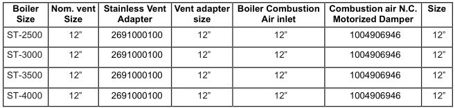
The table below summarizes the combustion air requirements for P-K STORM ™ boilers:
Direct Vent / Sealed Combustion Installations
The P-K Storm ™ series boilers are certified for operation in direct vent / sealed combustion systems, which feature combustion air intake ductwork which sources the combustion air supply from outdoors. The flow of combustion air through this ductwork is maintained by the appliance’s combustion blower.
The combustion air intake ductwork can be constructed with PVC, CPVC, single wall galvanized steel, or other suitable materials. The ductwork must be rigid enough to maintain the full required cross sectional area under all operating conditions.
NOTE: The combustion air intake ductwork must be sufficiently rigid in order to prevent collapse due to the potential for negative pressures inside the ductwork. If the ductwork collapses, this will restrict the combustion air supply to the appliance which may prohibit operation.
Proper sealing of the combustion air intake ductwork is necessary to prevent infiltration of air from conditioned space. For example, joints in PVC or CPVC piping must be cemented. For galvanized duct, wrap each joint and seam with adhesive aluminum tape or other sealant. Patterson-Kelley recommends installing a 1” x 1” or larger bird screen on the exterior termination. Ensure that the screen does not become blocked with snow, ice, insects etc.
The combustion air supply must be free from dust, lint, etc. The presence of such materials in the air supplied to the burner could cause nuisance “Low Air” shutdowns or premature burner failure. The appliance should not be operated during construction while the possibility of drywall dust, demolition dust, etc. exists. Patterson-Kelley offers an “Air Intake Filter” accessory on the Storm Boilers. If this accessory is installed, the boiler may be run in these conditions provided that the air filter is installed and maintained properly.
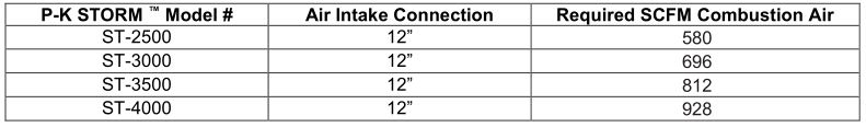
The combustion air supply must be completely free of chemical fumes which may be corrosive when burned in the appliance. Common chemicals which must be avoided are fluorocarbons and other halogenated compounds, most commonly present as refrigerants or solvents, such as Freon ® , trichloroethylene, perchloroethylene, chlorine, etc. These chemicals, when burned, cause improper combustion and premature appliance failure due to the formation of acids which quickly attack the heat exchanger and the flue piping materials.
Sizing the Combustion Air Intake DuctworkThe combustion air flow rate requirements per boiler model are summarized in 3.4.3. When sizing the combustion air intake ductwork, the pressure drop through this ductwork MUST NOT exceed 0.22” W.C. as described in the table below:
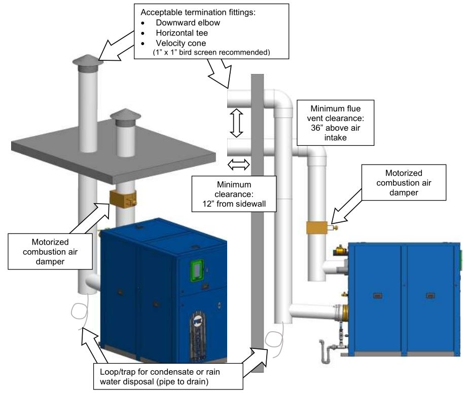
Motorized Combustion Air Dampers
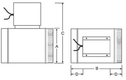
Patterson-Kelley recommends, and most installation codes require, the use of motorized combustion air dampers with end limit switches installed in the combustion air intake ductwork upstream of each appliance. This damper isolates the combustion air supply when the appliance is in standby. Once the appliance receives a call for heat, the motorized combustion air damper opens, and the end limit switch must close before the appliance can proceed to ignition. Patterson-Kelley offers motorized combustion air dampers with built-in end limits switches for sale, which are summarized in the table below:
Table of Recommended Motorized Combustion Air Dampers
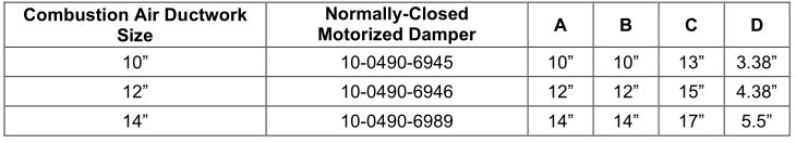
These normally-closed motorized combustion air dampers operate on 120 VAC and feature a built in end limit switch which must be wired to the appliances’ Air Damper Interlock circuit. Upon a call for heat, the boiler’s Air Damper Relay energizes, which drives the damper motor open. Once the damper reaches the fully-open position, the end limit switch makes contact and closes the Air Damper Interlock circuit, allowing the appliance to proceed to ignition. The diagram on the next page shows the wiring necessary to install the normally-closed motorized damper.
For correct installation of a vent system, read all of these instructions and refer to the vent manufacturer’s instructions.
Failure to use a proper vent system (types and materials) as described in this manual will void the appliance warranty and may result in rapid deterioration of the venting system, creating a health or life safety hazard. Faulty vent installation can allow toxic fumes to be released into living areas. This may cause property damage, injury, or death
NOTE: The power source to drive the damper actuator motor must be provided externally. The appliance DOES NOT provide a power source for this purpose.
NOTE: Combustion air dampers other than those listed in the table above may require voltages other than 120VAC. This is acceptable, provided the required voltage does not exceed 120VAC.
NOTE: The Air Damper Interlock circuit for the end limit switch is always 120VAC which is sourced from the appliance itself. All end limit switches must be rated for 120VAC.
Motorized combustion air dampers must be powered from an external power supply other than the appliance. The figure below shows a sample installation in which Relay C is user-selected to operate a 120VAC motorized air damper. Relay C is normally-open, so when the appliance is in standby, the combustion air damper remains closed. Once a call for heat is received, Relay C closes the 120VAC circuit (external power supply) which provides power to the damper motor, opening the damper. Once the motorized damper is fully-open, its end limit switch completes the Air Damper Interlock circuit (120VAC) which allows the appliance to proceed to ignition.
External power supplies are required for Relay A, Relay B, Relay C, and Relay D. Because power is provided from an external source, the power is still present when the appliance is turned off. Check all voltage sources have been disconnected prior to servicing. Failure to do so could result in electrocution, injury, or death.
Note: The NURO ® control allows the user to allocate Relay A, B, or C for use with a motorized combustion air damper. The figure above shows Relay C in use for the motorized combustion air damper. Depending on the user-configuration, Relay a, Relay B, or Relay C can be selected to operate the combustion air damper.
NOTICE !Relay A, Relay B, Relay C, and Relay D are rated for a maximum voltage of 120VAC and a maximum current capacity of 1/2 Amp. Customer must supply fusing for all current connected to the relays. Connecting a motorized damper which exceeds the voltage or current capacity of the relay could cause permanent damage to the relay.
FUSED
Flue Gas / Exhaust Venting
All vent installations shall be in accordance with NFPA 54/ANSI Z223.1, the National Fuel Gas Code, or CAN/CSA-B149.1, the Natural Gas and Propane Installation Code, or applicable provisions of the local building codes.
The vent material to be used for US and Canada is listed in the Table of Acceptable Materials for Venting Systems located in 2.5.4.
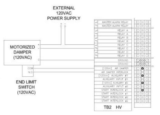
For interior clearance requirements, refer to 2.5.5. The vent shall extend at least three (3) feet above the roof, or at least two (2) feet above the highest part of any structure within ten (10) feet of the vent. Refer to 3.5.2 for an illustration of the flue termination. Additionally, the boiler vent shall terminate at least three (3) feet above a forced air inlet located within ten (10) feet.
To prevent the possible re-circulation of flue gases, the vent designer must take into consideration such things as prevailing winds, eddy zones, building configurations, etc. Patterson-Kelley cannot be responsible for the effects such adverse conditions may have on the operation of the appliances.
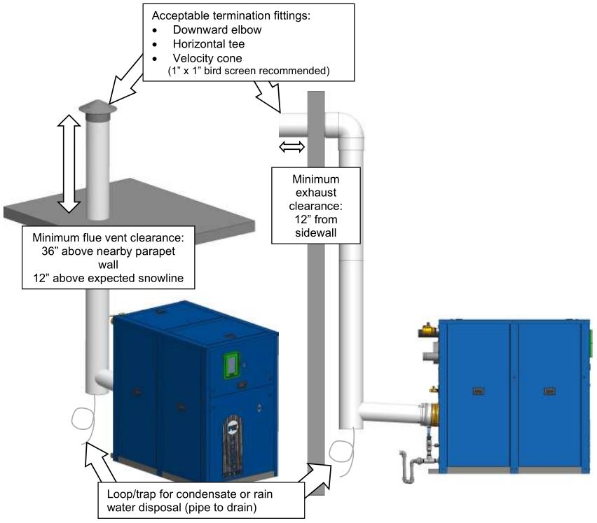
Vertical vents are allowed to be terminated with a variety of ends, including plain straight pipe, elbow, or vent tee. Horizontal vents must be terminated with an elbow or vent tee. Similarly, a bird screen with 1” x 1” openings is recommended for termination. Patterson-Kelley does not recommend using a vent rain cap of any type.
Category II or IV Venting Installation
P-K STORM ™ boilers are dual certified as Category II or IV appliances, as defined in ANSI Z21.13/CSA 4.9, latest edition and are not suit able for use with Type “B” Vents. The vent material to be used for US and Canada is listed in the Table of Acceptable Materials for Venting Systems located in 2.5.4.
Vent installations shall be in accordance with NFPA 54/ANSI Z223.1, the National Fuel Gas Code, or CAN/ CSA-B149.1, the Natural Gas and Propane Installation Code, or applicable provisions of the local building codes.
NOTE : For Category II installations, ensure the flue venting system is designed to maintain a slightly negative exhaust pressure between -0.01” W.C. and -0.05” W.C.
NOTE : For Category IV installations, ensure the flue venting system is designed to maintain a slightly positive exhaust pressure which MUST BE in the following ranges:
- +0.01” W.C. and +0.22” W.C. (Direct Vent / Sealed Combustion)
- +0.01” W.C. and +0.4” W.C. (Exhaust Only)
Vent SizingThe vent must be sized in accordance with the ASHRAE Systems and Equipment handbook, Chapter 30 or according to the vent manufacturer’s recommendations. When using manufactured venting systems, consult your vent supplier for correct sizing and structural support requirements. See the table below table for vent design parameters.

Vent Termination
For interior clearance requirements, refer to 2.5.5. The vent shall extend at least three (3) feet above the roof, or at least two (2) feet above the highest part of any structure within ten (10) feet of the vent. This is illustrated in the following diagram.Additionally, the boiler vent shall terminate at least 3 ft. above a forced air inlet located within 10 ft.
Venting for Multiple Boilers
While the vent design parameters outlined in 3.4 and 3.5 still apply, achieving those same parameters in a combined vent system adds a significant degree of complexity. Therefore, venting systems for multiple appliances shall be designed by experienced and knowledgeable venting professionals. The venting system shall be designed to prevent backflow of exhaust gas through idle appliances. For combined breeching installations, please follow recommendations of a qualified venting engineer/manufacturer.
Patterson-Kelley recommends that common venting systems be designed for a maximum continuous exhaust pressure of -0.04” W.C. when measured in the common vent. Locking inline dampers are recommended on the exhaust connection of each individual appliance in order to control the exhaust back pressure within the appliance and upstream of this damper. The -0.04” W.C. in the common flue will also help make sure the exhaust gases from an online appliance does not backflow through offline appliance(s).
In addition, Patterson-Kelley also recommends the use of motorized combustion air dampers in the combustion air intake ductwork of each individual appliance. When an appliance is offline, its combustion air damper will remain closed which will also help prevent the backflow of flue gases from online appliances. Please refer to 3.4.5 for more information.
If the common venting system uses a draft inducer fan or damper device, this MUST be interlocked with the appliances. In the event this draft inducer device fails, the interlock circuits to the appliances must be opened in order to prevent operation. Failure to do so could result in appliance operation under excessive back pressure conditions which could result in damage to the appliance and lead to serious injury or death.
The design of any common venting system MUST prevent backflow of combustion gases through offline boilers or water heaters. Failure to do so could result in damage to the appliance and lead to serious injury or death.
Sealed Combustion/Direct Vent Systems
These boilers are also certified for operation with a sealed combustion air and pressurized venting system. Such a system employs a sealed combustion air intake duct leading from outdoors and a sealed exhaust vent terminating outdoors. Air flow through the system is maintained by the combustion air fan. Allowable configurations of vent and air intake terminations are illustrated below.
NOTEThe exhaust vent must be at least 3 feet above the air intake. The air intake and exhaust vent must extend 6″ to 12″ from the exterior wall and be offset. The inlet air duct loss should not exceed 0.22” W.C.
The combined pressure drop of the air supply duct and exhaust vent must not exceed 0.44” W.C. This pressure drop includes both the inlet and exhaust duct friction loss. The air inlet and the exhaust vent must terminate on the same wall of the building and they must utilize fittings as shown below. This boiler may be installed with sidewall vent using room air.
STORM ™ Category II/IV:Through-the-roof (exhaust only)
STORM ™ Category II/IV:Sidewall (exhaust only)
NOTE : For Category II installations, ensure the flue venting system is designed to maintain a slightly negative exhaust pressure between -0.01” W.C. and -0.05” W.C.
NOTE : For Category IV installations, ensure the flue venting system is designed to maintain a slightly positive exhaust pressure which MUST BE in the following ranges:
- +0.01” W.C. and +0.22” W.C. (Direct Vent / Sealed Combustion)
- +0.01” W.C. and +0.4” W.C. (Exhaust Only)
When terminating on the same vertical axis, the air intake must use a 90° termination and the exhaust must have a 45° termination.
Inlet Duct Connection to Boiler
Connect the air supply duct to the inlet air collar on the boiler. The air inlet collar is 12” OD. Fasten the air inlet duct to the collar with sheet metal screws at 90° angles and seal with aluminum tape or sealant.
Intake Duct Materials and Sizes
The air intake duct can be fabricated from PVC, CPVC, single wall galvanized steel, or other suitable materials. The duct must be rigid enough to maintain the full required cross sectional area under all operating conditions. Proper sealing of the intake ductwork is necessary to prevent infiltration of air from conditioned space. Joints in PVC or CPVC must be cemented. For galvanized duct, wrap each joint and seam with adhesive aluminum tape or other sealant. The installation of a birdscreen on the intake termination is recommended. Ensure that the screen does not become blocked with snow, ice, insects, etc.
Category II Installations
The STORM boilers are dual-certified for either Category II or Category IV operation. Category II appliances operate with a non-positive vent static pressure and with a vent temperature that may cause excessive condensate production in the vent. There are several requirements for reliable operation of the boilers under Category II conditions:
- A normally-closed motorized damper is required on the boiler’s air intake. See the table below for the applicable part numbers.
- The draft, measured inside the vent at the rear of the boiler, must not exceed -0.05” W.C. Excessive negative draft will cause nuisance trips such as flame failures.
- The vent system must be properly drained of condensate before returning to the boiler. See 3.7.6 for information on installing condensate drains in the exhaust vent.
Table of Required Category II Motorized Dampers
A normally-closed motorized combustion air damper with end limit switch is required for Category II vent installations and is optional for Category IV vent installations. 120VAC motorized dampers with end limit switches are available for purchase from Patterson-Kelley. Other damper motor voltages are acceptable, provided they do not exceed 120VAC. The Air Damper Interlock circuit for the end limit switch is always 120VAC which is sourced from the boiler itself. All end limit switches must be rated for a minimum 120VAC.
Category IV Installations
If the vent installation is designed for Category IV conditions only (condensing – positive pressure) as it is defined in ANSI Z21.13/CSA 4.9, latest edition. The installations shall be in accordance with NFPA 54/ANSI Z223.1, the National Fuel Gas Code, or CAN/CSA-B149.1, the Natural Gas and Propane Installation Code, or applicable provisions of the local building codes.
Do not use a barometric damper if operating with a positive stack pressure (Category IV). Harmful flue gases may leak into the room which can cause serious injury or death.
Stainless Steel Venting
The following materials are used by venting manufacturers to produce listed venting systems.
- AL29-4C Stainless Steel Vent Systems listed and labeled to UL1738 Venting Systems for Gas-Burning Appliances, Categories II, III, and IV
- 316L Stainless Steel where certified and warranted by the vent manufacturer for venting of Category II, III or IV appliances
These prefabricated venting systems must be installed according to the manufacturer’s installation instructions. Special care should be taken to ensure that any and all integral gasketing is properly assembled and creates a gas and water tight seal. Systems that require silicone caulking for gasketing should only be installed with silicone caulk that is recommended by the vent manufacturer, or if none is recommended, only high temperature, waterproof, silicone caulk should be used. Support of venting system must be according to the manufacturer’s instructions. The boiler collar shall not be used to support the weight of the vent.
CPVC Vent System Installation
Install CPVC vent systems in accordance with this manual and the SMACNA Thermoplastic Duct Construction Manual. Install manufactured vent systems in accordance with the manufacturer’s listing and instructions. A customer supplied adapter is required to be installed between the boiler and the CPVC venting.
Operating Parameters:
- Maximum Water Temperature Set Point 180°F
- Flue Gas Limit 194°F
Installation Parameters:
- Cement and primer must conform to ASTM F493
- Three feet of venting closest to the boiler must not be enclosed
- The vent shall not be insulated
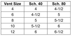
CPVC Support Spacing (Feet)
CONDENSATE DRAIN, TRAP & DISPOSAL
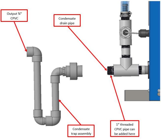
All STORM boilers produce a significant amount of condensate. The condensate drain is under slightly positive flue pressure, so the provided 3/4″ CPVC condensate trap must always be used. This trap is sized and designed to fill with the proper amount of condensate to create a liquid barrier to prevent flue gases escaping through the condensate drain into the installed space.
The trap included with this unit must be installed and maintained as described in these instructions and must be included as part of the condensate piping system. This trap is required to keep potentially hazardous products of combustion from continually entering the installed space where the condensate piping terminates. Failure to properly install this trap can cause, personal injury, exposure to hazardous materials or death.
- The condensate drain is located at the bottom rear of the appliance near the flue outlet. Connect the condensate trap assembly to the condensate drain pipe. Additional 1” threaded CPVC pipe can be added to the condensate drain connection to relocate the condensate trap assembly as long as all added parts are at a 1° downward slope. After attachment, the trap must be rotated so the offset in the pipe aims down toward the floor. Do not rotate the offset toward the ceiling. Do not use tools to tighten the CPVC union. Hand-tighten the CPVC union to seat the internal gasket.
- Do not combine condensate drains from multiple condensing appliances into a single drain line. Route each drain line into a drain suitable for condensate and make certain the end of the drain line is not submerged or otherwise blocked.
- All condensate plumbing must be protected from freezing. Do not locate the condensate piping such that an ice dam of frozen condensate can block condensate from leaving the outlet.
- The condensate is slightly acidic (3-5 PH), however, local codes may require it to be neutralized prior to entering the drainage system. An optional, field installed, Condensate Neutralization System is available from Patterson-Kelley.
- All piping from the condensate trap to the suitable drain must remain below the highest point(top of the condensate outlet pipe) on the properly attached condensate assembly.
- Connection to the condensate trap assembly should be made through either a barbed fitting or CPVC piping (user supplied). If piping with CPVC, it is recommended that an additional union is put in to allow for trap cleaning and removal.
Condensate Trap must be piped to drain in accordance with all national, state and local codes. If installed outdoors, it must be field heat traced.
Refer to image on the following page for proper installation on the condensate drain.
Removing an Existing Boiler
When an existing boiler is removed from a common venting system, the common venting system is likely to be too large for proper venting of the appliances remaining connected to it.
At the time of removal of an existing boiler, while the other appliances remaining connected to the common venting system are not in operation, the following steps should be followed with each appliance remaining connected to the common venting system placed in operation:
- Seal any unused openings in the common venting system.
- Visually inspect the venting system for proper size and horizontal pitch and determine that there is no blockage or restriction, leakage, corrosion or other deficiency which could cause an unsafe condition.
- Insofar as is practical, close all building doors and windows and all doors between the space in which the appliance remaining connected to the common venting system are located and other spaces of the building. Turn on clothes dryers and any appliances not connected to the common venting system. Turn on any exhaust fans, such as range hoods and bathroom exhausts, so they will operate at maximum speed. Do not operate a summer exhaust fan. Close fireplace dampers.
- Place the appliance being inspected in operation. Follow the lighting instructions. Adjust the thermostat so that the appliance will operate continuously.
- Test for spillage at the draft hood relief opening after 5 minutes of main burner operation. Use the flame of a match or candle or smoke from a cigarette, cigar or pipe.
- After it has been determined that each appliance remaining connected to the common venting system properly vents when tested as outlined above, return doors, windows, exhaust fans, fireplace dampers and any other gas-burning appliance to their previous conditions of use.
Any improper operation of the common venting system should be corrected so the installation conforms to the National Fuel Gas Code, ANSI Z223.1 and CSA B149 Installation Code. When resizing any portion of the common venting system, the common vent system should be resized to approach the minimum size as determined using the appropriate tables in part 11 of the National Fuel Gas Code, ANSI Z223.1/NFPA 54 and/or CAN/CSA B149.1 Natural Gas and Propane Installation Code.
All threaded connections must be made using a pipe compound that is resistant to the action of liquefied petroleum gases. Do not use Teflon tape on gas line threads!
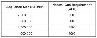
NOTICE ! See Pipe Capacity for Natural Gas & Propane Gas charts on the following pages for required pipe size, based on overall length of pipe from the meter plus equivalent length of all fittings. Approximate sizing may be based on 1 cubicfoot of natural gas per 1,000 Btu/Hr input, i.e., 3,000,000 Btu/Hr requires about 3,000 cubic feet per hour.
Piping
Gas Piping Overview
Before making the gas hook-up, make sure the boiler is being supplied with the type of fuel shown on the boiler nameplate.
The boiler shall be installed such that the gas ignition system components are protected from water (dripping, spraying, rain, etc.) during appliance operation and service (circulator replacement, control adjustment, etc.).
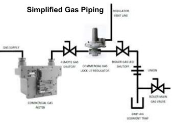
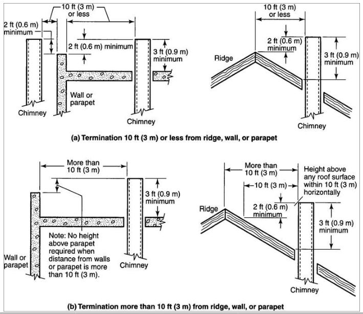
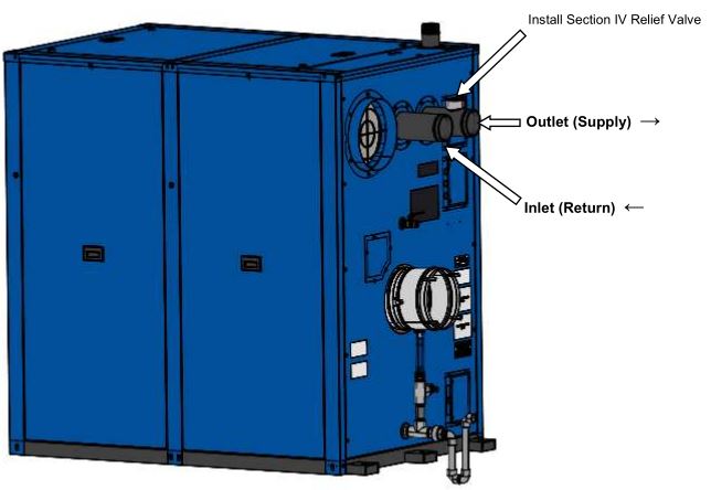
The boiler is factory fire-tested and adjusted for proper combustion. The gas train components are certified to handle a maximum inlet pressure of 14″ W.C. (1/2 psig). Typical gas pressure supply for natural gas is 7″ W.C. If the available gas pressure exceeds 14″ W.C., a suitable additional intermediate gas pressure regulator of the “lock up” type must be provided to reduce the pressure to less than 14″ W.C. Refer to the table below or the appliance’s label for the minimum inlet gas pressure.
![]()
Note: When using a vented lock-up gas pressure regulator, the vent piping should be increased by one pipe size for every 10 equivalent feet of length. Never connect vent piping that is smaller in size than the gas regulator’s vent port connection.
This unit comes with a sediment trap (drip leg) already installed. Patterson-Kelley recommends a union connection ahead of the primary manual shutoff valve on the boiler. A gas piping schematic is shown above. Gas piping should be installed in accordance with National Fuel Gas Code, ANSI Z223.1, latest edition, and any other local codes which may apply; in Canada see CAN/CSA-B.149.1, latest edition. In the Commonwealth of Massachusetts, the gas cock must be a “T-handle type.”
Natural Gas Piping
The table below should be used to size the natural gas piping to the appliance. The approximate energy content of natural gas is 1,000 BTU / cu. Ft:
Pipe Capacity for Natural Gas
Pressure Testing the Gas Piping
The appliance and all gas piping connections should be pressure-tested and must be checked for leaks before being placed into service. The appliance must be disconnected at the manual shut-off valve (located at the end of the supplied gas train) from the gas supply piping during any pressure testing of the system at pressures in excess of 0.0723 psig (2″ W.C.). Perform the pressure test with compressed air or inert gas if possible.
Some leak test methods, including the use of soap and water, may cause corrosion of the carbon steel gas pipe fittings. If using soap and water or a similar leak test method, make sure to clean off all moisture from the gas pipe fittings prior to placing the appliance into service.
Boiler Water Piping
The boiler piping system of a hot water heating boiler connected to heating coils located in air handling units, where they may be exposed to refrigerated air circulation, must be equipped with flow control valves or other automatic means to prevent gravity circulation of the boiler water during the cooling cycle.
NOTICE ! Condensate Trap must be piped to condensate neutralization tank & floor drain in accordance with all national, state, and local codes. Heat trace may be required to prevent freezing in un-insulated spaces.
NOTICE ! The PK STORM boiler is furnished with two 4” grooved connections and Victaulic Style 75 couplings. These couplings must be used with the EPDM Victaulic seals. Isolating valves must be installed in both the inlet and outlet water connections.
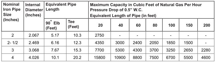
Boiler Inlet and Outlet Connections
All water connections should be in compliance with national, state, and local code requirements. Adapters from Victaulic to NPT are available from Patterson-Kelley. The bottom rear connection to the boiler is the INLET and must be used for the return from the system. The top rear connection to the boiler is the OUTLET and must be connected as the supply to the system. All water piping must be installed such that no stresses are transmitted to the boiler. The boiler shall not be used as a pipe anchor.
Boiler Water Piping (for Installer)
StrainerTo avoid possible contamination of the boiler with dirt, rust, or sediment from the system, a strainer near the boiler inlet is strongly recommended. Even new systems may contain sufficient foreign material to eventually reduce the performance of the heat exchanger. Adequate circulation of good clean water is essential for maximum efficiency and long life of the boiler. Refer to Appendix D – Best Practices For New & Retrofit Systems for more information on best piping practices.
Heat ExchangerNOTICE !The boilers require a minimum operating water pressure of 14.5 psi.
Relief Valve PipingEach boiler is supplied with a pressure-relief valve sized in accordance with ASME requirements. The relief valve discharge must be piped to an acceptable drain at a safe point of discharge. Reducing couplings or other restrictions are not permitted in the discharge line.The PK Storm boilers require an ASME Section IV relief valve to be installed on the top of the OUTLET (Supply) connection. The spindle of the relief valve must be vertical. The ASME Section IV relief valves are available for purchase from Patterson-Kelley.
Low Water Cut-OffThe boiler is furnished with a probe-type low water cut-off; no field piping is required. If the water level in the boiler drops below the probe, the boiler will shut down and LOCKOUT LOW WATER LEVEL will be displayed on the control panel. The low water cutoff circuit will automatically reset when the low water condition clears; however, the boiler controls will retain the lockout condition until the reset button on the display is depressed. Installation of external limit controls may be required by certain codes or in certain installations. Review applicable local codes for details.
NOTICE! Some local jurisdictions may require an auxiliary low water cut-off device installed in the external piping. The auxiliary low water cutoff device only prevents operation when the water level in the appliance is insufficient. It does not detect low water conditions in other parts of the system. Installation of automatic air vents in the “high points” of the piping or additional low water safety devices should be considered to protect the system.
Drain Valve and PipingThe P-K Storm ™ boilers feature a ¾” drain connection. Prior to draining the boiler, electrical power and gas supply must be turned off to the boiler, and the boiler must be isolated from the system at the supply and return connections.
NOTICE! The 3/4” manual drain is for draining the water inside the heat exchanger only, not the entire hydronic or domestic system. Draining the entire system through the boiler or water heater’s drain valve will deposit sediment and debris from the system inside the heat exchanger. This will result in poor heat transfer and premature failure. Refer to Appendix D – Best Practices For New & Retrofit Systems for more information on best piping practices.
Condensate DrainThe condensate is acidic (pH between 3.0 and 5.0) and may be corrosive to some building drain systems. A condensate neutralization system may be required and is available from Patterson-Kelley. If the condensate drainage system is exposed to freezing temperatures, it must be field heat traced. The boiler could generate up to one gallon of condensate per 100,000 BTU input. As an example, an ST-2500 boiler at full fire can produce 25 gallons per hour of condensate. Disposal of condensate must comply with all state and local codes.
Piping with Refrigeration SystemsWhen installed in a two-pipe system that provides both chilled and hot water, the control system should be configured so as to limit the time rate of change of temperature at the boiler. Consult your authorized Patterson-Kelley boiler representative for application guidance.
Piping with air handling unitsThe boiler piping system of a hot water heating boiler connected to heating coils located in air handling units, where they may be exposed to refrigerated air circulation, must be equipped with flow control valves or other automatic means to prevent gravity circulation of the boiler water during the cooling cycle.
Water Quality
The P-K Storm ™ boiler’s heat exchanger is made of a stainless steel alloy. The heat exchanger requires proper water conditions to remain efficient and function properly. Information of proper water treatment can be found on our website www.pattersonkelley.com type in search: “water quality”. For information, please refer to Patterson-Kelley Multi-Metal Systems Water Quality Standards as it appears in Appendix C – Water Quality Standards Quality Standards for Hydronic Boilers in Multi-Metal Systems as this applies to the warranty of your heat exchanger. Under no circumstances should Soften Water be used in boiler.
NOTICE! The chemical manufacturer for use must certify glycol or other treatment chemicals added to the system in multi-metal systems that include a copper heat exchanger.
Under no circumstances should petroleum based cleaning or sealing compounds be used in the boiler system.
Under no circumstances should the hydronic system be flushed while the appliance is attached to the system since the debris or corrosion products may accumulate in the appliance and obstruct the appliance’s heat exchanger.
If the piping system attached to this unit will be chemically cleaned, the boiler must be disconnected from the system and a bypass installed so that the chemical cleaning solution does not circulate through the boiler. Following chemical cleaning, the system should be thoroughly rinsed to remove cleaning agents prior to reconnecting the boiler to the system.
Pre-Start Checklist
Never attempt to operate a boiler that has failed to pass all the safety checks described below. Operating a boiler that has failed a safety check could result in injury. Bypassing safety mechanisms will result in unsafe boiler operation which couldresult in injury or death. After checking controls by manual adjustment, make sure they are always reset to their proper settings.
Before attempting to start the boiler, make sure the following items have been completed.
- Inspect the gas train, blower, ignition electrode, and boiler in general to be sure there was no damage during shipment or installation.
- Flue gas from the boiler is properly vented.
- Gas connection has been made, pressure tested for leakage and the line purged of air. Make sure all required vents have been installed.
- Water connections are complete, and the boiler and system have been filled and purged of air.
- The boiler is connected to the correct electrical power source listed on the nameplate, a disconnect having adequate overload protection is required.
- Combustion air openings are not obstructed in any way and have adequate capacity.
- The boiler is placed the proper distance from any combustible walls.
- Relief valves have been piped to an acceptable drain at a safe point of discharge.
- Condensate piping is properly connected.
- Verify system water quality is within specifications.
Safety Checks
he user should become thoroughly familiar with the operation of the boiler and controls before attempting to make any adjustments. Changing parameters requires an understanding of the parameters and the functionality of the boiler. The boiler may not function properly if parameters are changed from the factory values.
The following checks of safety systems must be made before putting the boiler into normal operation. Before firing the boiler refer to Section 4 for information on the use of the controls, lighting, and shut-down procedures.
Ignition Safety System Test
Test the ignition system safety shutdown as follows:
- Cycle the boiler on by generating a heat request. (The method for this will depend on your boiler configuration.)
- During the pre-purge cycle (before ignition), smoothly close the downstream manual isolation valve (inside the boiler cabinet) to reduce the gas flow.
- Closing the manual isolation valve will prevent a successful ignition, and the NURO will display either:109: “Ignition Failed”110: “Ignition Failure Occurred”
These alarms indicate an ignition failure and the lockout will remain until the control is reset. After completing this test, turn the boiler off, open the downstream manual isolation valve, then turn the boiler back on.
Low Water Cut-Out Test
The boiler is furnished with a probe-type low water cut-out. The probe is installed near the boiler’s outlet in order to detect the presence of water at the highest possible location in the boiler and is connected to the low water cut-out circuit board by a single wire. The low water cut-out circuit board is located inside the boiler’s front door, toward the bottom left of the control panel and is identified with a label.
In order to test the low water cut-out, press and hold the red “Push to Test” button for at least 5 seconds. A manual lockout reset error displaying 10010: “Low Water Limit” on the NURO touchscreen should occur. The red LED indicator on the Low Water cut-off will no longer be illuminated.
Optional Test Method: First turn the boiler off, and then turn off the boiler’s circulating pump. Isolate the boiler from the system. Drain the water level below the low water cut-off probe. Turn the boiler back on. It should not operate, and a manual lockout reset error displaying 10010: “Low Water Limit” on the NURO touchscreen should occur. The red LED indicator on the Low Water cut-off will no longer be illuminated.
Return the system to normal operation by refilling with water, restarting the boiler’s circulating pump, and then turning the boiler back on.
Flow Switch Test
The appliance is equipped with a paddle type flow switch installed in the hot water outlet piping. In order to test the flow switch, provide a call for heat to the appliance. Once the appliance has begun its pre-purge sequence, stop the water flow by closing an isolation valve or turning off the circulation pump. The NURO control should display a “HOLD” error and not allow the appliance to proceed to ignition. Re-establish flow through the appliance by reopening the isolation valve or turning on the circulation pump.
Manual Reset High Temperature Limit Test
The boiler is furnished with two manual reset high temperature limits. Both probes are installed near the boiler’s outlet in order to measure the outgoing supply water temperature. Each probe is connected to a manual reset high temperature limit by a thin, metal capillary tube. The first high temperature limit switch is located inside the boiler’s front door, towards the left of the control panel and is identified with a label. The second high temperature limit switch is located inside the boilers’ first left side panel, in front of the gas valve, in the water outlet manifold. These high temperature limit switches are wired in series; thus tripping either switch will result in the unit displaying an error. In the case of the NURO touchscreen displaying 100009: “High Temperature Limit” both high temperature limit switches will need to be manual reset.
Test each of the manual reset high temperature limit controls as follows:
- Cycle the boiler on by generating a heat request.
- Allow the boiler to proceed through ignition until main flame is established.
- Using a flathead screwdriver, turn down the setting on the manual reset high temperature limit to its lowest value. Turning the screwdriver counter-clockwise decreases the temperature setting.
- When the outgoing supply water temperature exceeds the setting on the manual reset high temperature limit, the main burner will shut off.
- The NURO touchscreen will display 10009: “High Temperature Limit”. Return the system to normal operation by readjusting the setting on the manual reset high temperature limit to its default setting, press the reset button on the manual reset high temperature limit, and finally touch any prompts from the NURO control.
These manual reset high temperature limits are wired in series so if only one switch trips, it would result in the unit locking out.
Gas Pressure Switch Tests
Low Gas Pressure SwitchThe boiler is furnished with a low gas pressure switch, installed near the boiler’s main gas shutoff/control valve. The operation of this switch must be checked as follows:
- Close the main gas cock (external to the boiler).
- Cycle the boiler on by generating a heat request.
- Allow the boiler to proceed through prepurge and attempt ignition.
When the main gas shutoff/control valve opens to attempt ignition, the low gas pressure switch will trip, causing the NURO touchscreen to display 10012: “Low Gas Limit”. Even after re-opening the main gas cock, 10012: “Low Gas Limit” will remain on the NURO display until the boiler is manually reset by pressing “Reset Control”.
NOTEMake sure to re-open the main gas cock (external to the boiler) after a successful test.
High Gas Pressure SwitchThe boiler is furnished with a high gas pressure switch, installed near the boiler’s main gas shutoff/control valve. The operation of this switch must be checked as follows:
- Before starting the boiler, close the downstream gas cock located inside the boiler’s enclosure.
- Cycle the boiler on by generating a heat request.
- Allow the boiler to proceed through prepurge and attempt ignition.
NOTEMake sure to re-open the downstream gas cock (inside the boiler) after a successful test.
Fuel/Air Adjustments
The P-K Storm ™ boilers are equipped with a gas/air ratio control valve and a gas safety shut off control valve, combined into one valve assembly. The valve functions in series with the variable speed combustion blower to supply the correct gas/air mixture for optimum firing performance and efficiency. The combustion blower speed is controlled automatically by the boiler controller. The blower speed determines the amount of air flow and the amount of suction/negative pressure atthe gas valves. The gas valve adjusts gas flow to maintain the proper delivery pressure at the outlet of the valve.
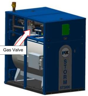
Gas Pressure Adjustment
See rating plate for the minimum and maximum gas pressure of the boiler. The supply pressure during main burner operation must be greater than the minimum indicated on the rating plate. Nominal gas supply pressure is 7” W.C. for natural gas. The gas pressure must not exceed 14” W.C. which is the maximum allowable pressure on the gas train components. Each boiler is furnished with a manual shut-off valve which has an integrated test port. This port is located on the upstream side of the valve body for measuring supply pressure.
The air flow is pre-set at the factory prior to shipment. Gas flow is dependent primarily on fan speed not upstream gas pressure. The automatic gas valve may have to be adjusted to obtain proper combustion readings for specific local conditions. A combustion analyzer must be used. Combustion must be set in accordance with Recommended Combustion Settings for P-K Storm Boilers in Section 3.11.2.
Manual Control Mode for High and Low Fire Adjustment
To adjust/tune combustion, use the NURO’s “Manual Control Firing Rate” mode. To access this mode, touch the “Info” button in the lower left corner of the screen, and then press “Service” in the lower left. Next, touch “Press to Activate Manual Control” which will open the “Manual Control Firing Rate” mode.
This test mode should be used when adjusting or tuning the gas safety shut off/control valve.
NOTE: Proper water flow should be established before performing any combustion adjustments to ensure the boiler doesn’t short-cycle or overheat.
Once in “Manual Control Firing Rate” mode, a heat request is required. Once the appliance cycles on and is running in “Manual Control Firing Rate”, use the UP and DOWN arrows or the slider to force the boiler to operate at low fire, high fire, or anywhere in-between. To prevent the appliance from cycling off prematurely during adjustment, ensure that any load devices (air handlers, control valves, radiators, air handling units, etc.) are in operation and are able to shed/dump the heat created by the boiler.
Recommended Combustion Settings for P-K STORM Boilers
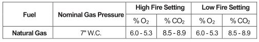
The P-K Storm ™ boilers are equipped with a combination gas/air control and gas safety shut off control valve. The “zero governor” gas valve responds to the variable speed combustion blower in order to supply the correct air/gas ratio for optimum performance and efficiency.
NOTICE! For high altitude adjustments (greater than 2,000 feet above sea level), see Appendix B – Boiler Altitude Derate Schedule at the end of this manual.
Adjusting High Fire
NOTE: ALWAYS adjust high fire combustion first!
Start the boiler and observe proper operating parameters for the system. Access the “Manual Control Firing Rate”, as described above, and increase the firing rate to 100%. Check combustion readings using the combustion analyzer. If the combustion readings are not in accordance with Section 3.11.2, adjust as follows:
Required Tools: Flat head screwdriver, Combustion analyzer and water tube manometer.
- Using a slotted screw driver, set the maximum restrictor (high fire screw) on the outlet/shutter flange of the combination gas safety shut off / control valve by turning clockwise or counterclockwise to achieve the desired CO 2 or O 2 level. To increase the O 2 level, adjust towards the “-“ symbol to decrease gas flow. To decrease the O 2 level, adjust towards the “+” symbol to increase gas flow.
- There will be a slight time delay between the adjustment and the response of the CO 2 /O 2 measuring instrument. Clockwise rotation decreases gas flow. Counterclockwise rotation increases gas flow.
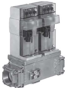
Adjusting Low Fire
Required Tools: 4 mm hex wrench and combustion analyzer.
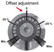
Start the boiler and observe proper operating parameters for the system. Set boiler to the “ Manual Control Firing Rate ” mode, as described above, and decrease the firing rate to 0%. Once the boiler has reached low fire operation, check combustion readings using the combustion analyzer. If combustion readings are not in accordance with the above table, adjust as follows:
- Using a 4 mm hex wrench, adjust the pressure regulator offset adjustment (pictured above) to achieve the desired CO 2 /O 2 level. To increase the O2 level, adjust towards the “-“ symbol to decrease gas flow. To decrease the O2 level, adjust towards the “+” symbol to increase gas flow.
- Adjustments to the offset pressure regulator should not exceed 1/2 of a hash mark turn at a time before allowing the readings to respond and stabilize. (NOTE: Offset adjustment is extremely sensitive, make small adjustments).
Following all gas valve adjustments, check for proper light-off and verify correct fuel/air mix and combustion quality throughout the entire firing rate (from low to high fire).
Checking Flame Signal
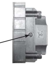
Touch the “Info” button in the lower left corner of the NURO display to load the “Information” menu which shows real-time read-only boiler values such as temperatures, relay states, etc. Scroll down the “Information” menu to find the “Flame Signal” value. This value displays the strength of the combustion flame (units = V) as measured by the ignition electrode/ionization probe. When the boiler is in standby, prepurge, or postpurge the flame signal should read 0V. During main flame, a strong flame signal should read between 8-30V.
Initial NURO Control Setup and Adjustment
This manual covers basic NURO control setup and adjustment. For a walkthrough of the complete control setup, please refer to the NURO Boiler Controller: Advanced User’s Guide, Part Number is 1004905979 which is helpful for more complex installations. For more complex boiler or water heater applications and more information on the parameters, please refer to the NURO Advanced User’s Guide.
Startup
When the boiler or water heater is powered on, the NURO touchscreen will display an initial Startup Screen then the Local Representative screen. This shows the name, address and phone number of the local Patterson Kelley representative.
Home Screen
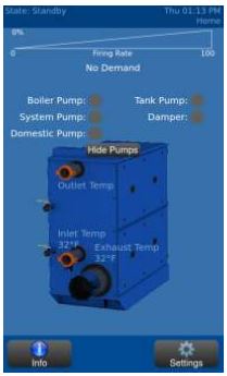
After a brief time, the Local Representative information screen will timeout displaying the Home Screen. The Home Screen shows a snapshot of the boiler or water heater’s current operating conditions:
- Outlet (Supply) Temperature
- Inlet (Return) Temperature
- Exhaust Temperature
- Firing Rate, etc.
Pressing the “Info” button in the lower left corner will load the Information screen.For the setup wizard, press the “Settings” button in the lower right corner to load the “Settings” or “Main Menu” screen.
Information Screen
The Information Screen contains real-time read-only values such as temperatures, relay states, etc. Scroll through the Information Screen by sliding your finger up or down. This screen is helpful to determine the operating characteristics.
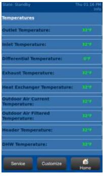
NOTEFor more information on any value, please refer to the NURO Boiler Controller: Advanced User’s Guide, Part Number is 1004905979.
Setup Wizard
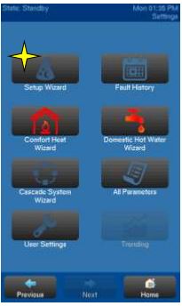
The Setup Wizard is recommended for all boilers and water heaters because it guides the user through setup for multiple applications (Standalone Comfort Heat, Standalone Domestic How Water, and/or Cascade operation). The Setup Wizard will guide the user through the parameter setup for all the relevant applications based on responses to a series of questions. To access the Setup Wizard, press <SETUP WIZARD> from the “SETTINGS” menu.
While navigating the Setup Wizard, press the desired buttons in the center content area. The selected choice will be indicated with a yellow light as seen below. To proceed to the next Setup Wizard screen, press <NEXT> at the bottom of the screen. The NURO ® control also allows the user to back-track at any time by pressing <PREVIOUS> in the bottom-left corner of the screen.
The Setup Wizard allows the user to assign functionality to the user-configurable Relays A through D. This allows the user to assign functions like “Boiler Pump”, “System Pump”, “Flame Detected”, and “Air Damper” to the relays.
NOTE: The relay assignments must agree with the wiring to/from the appliance. For example, if Relay A is user-configured to enable/disable the Boiler Pump, the control wires to operate the boiler pump must be properly wired to the Relay A terminals in the High Voltage (TB2) terminal block.
Typical Boiler Operating Conditions
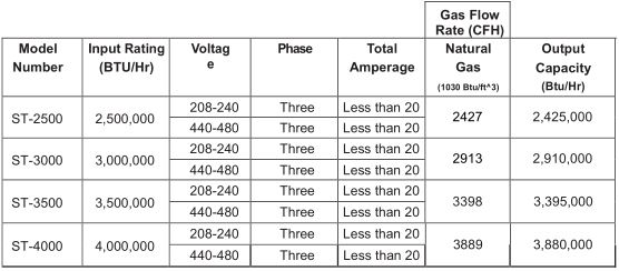
Operations
NURO ® Control Panel
Once the boiler has been installed in compliance with this manual, it is necessary to open the front door of the boiler in order to access the power (on/off) switch located on the NURO ® control panel as shown below:
Do not use this boiler if any part has been under water. Immediately call a qualified service technician to inspect the boiler and to replace any part of the control system and any gas control which has been under water. Failure to do so could result in electrocution, injury, or death.If overheating occurs or the gas supply fails to shut off, do not turn off or disconnect the electrical supply to the pump. Instead, shut off the gas supply at a location external to the boiler.
NOTICE ! The On/Off switch only interrupts power to the NURO ® control system. In order to fully remove power to the entire boiler, use the external disconnect.
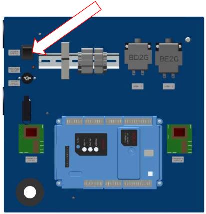
NURO Touch Screen Interface
Once the boiler is switched to the “ON” position, the P-K Storm boiler can be programmed and operated with the NURO ® touch screen interface located on the front door. A clear plastic cover protects the touch screen which can be opened by pinching the clasp and swinging open to the left.
Factory Tests
Safe lighting and other performance criteria were met with the gas manifold and control assembly provided on this boiler when the boiler underwent factory tests specified in ANSI Z21.13/CSA 4.9, latest edition. (See “Factory Firetest” label on the rear surface of the boiler).
Normal Lighting and Shut-down Procedures
Normal Lighting Procedures
- Make sure the system is filled with water and water is circulating in the system. Turn on electrical supply and open the gas supply valves to the boiler.
- Turn the on/off switch to the “On” position. If an error is indicated, refer to the NURO Advanced User’s Guide to troubleshoot the problem and take necessary corrective action before proceeding.
- Set the desired high temperature limit and operating temperature. The NURO ® controller will now begin the automatic firing sequence.
Normal Shut Down Procedures
- Allow the boiler to turn off on its own once the temperature satisfies or remove the call for heat to the boiler.
- Once the boiler completes a successful “Post-Purge” and “Post-Pump”, it will return to “Standby”.
- Once in standby, turn the on/off switch to the “Off” position.
- Close all manual gas valves to right.
- Turn off the electrical disconnect to the boiler.
Emergency Shut-Off
In case of emergency, immediately shut off the gas supply at the valve on the top surface of the boiler. See the image to the right for the locations of the Natural Gas valve.
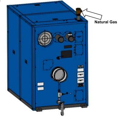
Maintenance
Preventative Maintenance
NOTICE! Proper maintenance schedule and record keeping is critical for optimum performance and to maintain the Patterson-Kelley warranty.
NOTE: The combustion blower motor is permanently lubricated and does not require periodic lubrication.
PRECAUTIONS ASSOCIATED WITH HANDLING REFRACTORY LINING MATERIAL
- This Patterson-Kelley product contains a Combustion Area lined with REFRACTORY CERAMIC FIBERS (RCFs) similar to many other devices produced in this industry.
- RCFs have been identified by the International Agency for Research on Cancer (IARC) as possibly being carcinogenic to Humans.
- AVOID breathing particles or dust from RCFs and avoid contact with Skin or Eyes.
- The National Institute for Occupational Safety and Health (NIOSH) recommends the use of a respirator meeting current standards, to avoid inhalation of dust. Also recommended is loose fitting, long sleeved clothing, eye protection and gloves whenever handling RCFs. Current NIOSH Recommendations are listed on their website at http://www.cdc.gov/niosh/homepage.html, which should be viewed before the handling or removal of Refractory Lining Materials on this or any similar device.
- Using a SPRAY BOTTLE, saturate with WATER; but not dripping, the combustion chamber lining to prevent dustfrom becoming airborne.
- Place removed RCFs into a plastic bag for disposal with normal trash.
- Wash exposed clothing (if not disposable), TWICE and DRY separately from other laundry.
Lockout/Tagout procedure must be employed when servicing this unit. Failure to do so could result in electrocution, injury, or death.
Label all wires prior to disconnection when servicing controls. Wiring errors can cause improper and dangerous operation.
Use care when reassembling main gas line and ensure all connections are tight. Use a leak detector to check for leaks before and after servicing any component of the gas piping. Failure to do so could result in injury or death.
Use care when servicing the boiler to prevent the accumulation of gas in or around the combustion chamber. Pockets of accumulated gas are subject to combustion and/or explosion which could result in injury or death.
Determine the cause of any lockout or errors before resetting the boiler. If able to determine cause of lockout, take appropriate corrective action. If unable to determine cause of the problem, call a qualified service technician. Verify proper operation after servicing.
Check daily to be sure that the boiler area is free and clear of any combustible materials, including flammable vapors and liquids.
Daily
Observe operating temperature and general conditions. Make sure that the flow of combustion and intake air to the appliance is not obstructed. Determine the cause of any service codes or lockouts on the NURO ® touchscreen display. Observe any unusual noises or operating conditions and make the necessary corrections. Notify responsible individuals for required corrective action or repair.
Check daily to be sure that the immediate area around the boiler or water heater is free and clear of any combustible materials, including flammable vapors and liquids.
Weekly
Observe the conditions of the main flame. A normal high fire flame is mostly blue, though the refractory in the rear of the heat exchanger will glow an orange red color. A normal low fire flame is also blue. The refractory may not show any orange-red color at low fire. Never attempt to adjust the flame “by eye”. The correct flame/combustion is dependent on the air and gas adjustment.
Correct air adjustment is essential to the efficient operation of this appliance. Ensure that the flow of combustion and ventilation air is not obstructed. If an adjustment in the combustion appears necessary, the flue gas composition should be checked with a combustion analyzer and compared to the values stated in the Combustion Setup and Adjustment combustion settings table in 3.11.2. If an adjustment to the combustion is necessary, call a qualified and knowledgeable installer or service agency that has been trained on the Patterson-Kelley appliance.
Monthly
- Press the “Info” button on the NURO ® touchscreen to load the Information Screen and scroll down to view the flame signal measured in Volts. Typical flame signals should read between 8-25V.
- Test the low water level cut-off. Refer to 3.10.2 (if applicable).
- Test the manual reset high-temp limit. Refer to 3.10.4.
- Test the low gas pressure switch. Refer to 3.10.5.
- Test operating temperature controls by reducing or increasing temperature settings as necessary to check burner operation.
- Check the combustion chamber condensate drain piping for leaks or obstructions.
NOTICE! Installation and service must be performed by a qualified installer or service agency that has been trained on the appliance.
Semi-Annually
In addition to the recommended monthly service:
- Check the burner for any accumulated dust or lint. You may clean the burner using only water to remove accumulated material. Refer to 5.2.
- Inspect burner for any signs of deterioration or corrosion. Replace immediately if deterioration or corrosion is evident.
- Check the pH level of the system fluid. Verify the pH is in accordance with Appendix C – Water Quality Standards Quality Standards for Hydronic Boilers in Multi-Metal Systems
- Inspect and clean the condensate system and check for leaks. If a condensate neutralization kit is present, open the lid and inspect the media. If they are absent or have been significantly worn away, replace them with new media.
Annually or 2500 Run Hours (Whichever Comes First)
In addition to the recommended monthly and semi-annual service:
NOTE: Patterson-Kelley recommends cleaning the heat exchanger at least once annually. Some of the items listed under this section are easily accessible during that procedure. Patterson-Kelley recommends annual maintenance and cleaning of the heat exchanger to be done simultaneously. Please refer to Section 5.2 for more information.
NOTE: This section recommends replacing parts of the boiler. Refer to section 6 for Parts/Technical Support. Spare parts and replacement parts can be ordered from Patterson-Kelley by calling toll free (877) 728-5351. Reach us by fax at (570) 476-7247.
- Inspect and clean the inlet screen (if applicable) of any accumulated dust or lint. If using an air filter, inspect and replace (if necessary). Patterson-Kelley suggests replacing air filters at least once per year.For the following points 2 through 4, refer to 5.2.
- Replace the ignition electrode and ionization rod (flame rod). Replace the gaskets for each as well. Note the geometry of the ignition electrode and the ionization rod (flame rod): if the spacing between the rods (after replacement) and the burner does not match factory recommendation, please consult Patterson-Kelley for correction actions. Refer to the following images for proper factory spacing — dimensions are in millimeters:

- Check burner for signs of deterioration or corrosion. Replace burner immediately if any deterioration, corrosion, or damage is found. If damage to the burner is suspect from improper combustion settings, be sure to do a combustion check to the factory preferred settings. The burner may be cleaned with water if any accumulated dust or lint is found. This must be done with the burner outside of the combustion chamber.
- Inspect combustion chamber when the burner door is open. Pay careful attention to the door O-Ring, Braided Rope Gasket, and the door’s insulation/refractory. If any of these show signs of damage or deterioration; they will need replaced immediately. Note any signs of deterioration or build-up of deposits on the coils of the heat exchanger. Clean as necessary following the procedure in 5.2.Drain and flush the water side of the heat exchanger as required (separate from system flush) using clean water only. This heat exchanger comes with a drain valve; it is located on the back of the heat exchanger above the exhaust vent. To flush water side of heat exchanger, it is recommended to first isolate the boiler from the system. Remove pressure from the boiler piping. It is then recommended to attach a hose or piping to the drain valve on the heat exchanger. That hose (or piping) should be run to a floor drain. Open the drain valve to drain water from the boiler piping. It is then recommended to remove the flow switch from the outlet piping. Once the flow switch is removed, utilize the 1” NPT opening to attach a hose. The hose should then be pressurized with clean water, with the drain valve to the boiler open and piped to a floor drain. Flush the heat exchanger for several minutes. When complete, remove any hoses or piping, and reinstall components to their operating positions. DO NOT ALLOW THE DRAIN VALVE TO BE OPEN INSIDE THE CABINET WITHOUT RUNNING PIPE OR HOSE TO A DRAIN.***Do this flush at low pressures— just enough pressure to push water through the exchanger and out of the drain valve***.
- Take a sample of the system fluid and verify the water quality complies with the standard defined in Appendix C – Water Quality Standards Quality Standards for Hydronic Boilersin Multi-Metal Systems.
- Inspect and clean the condensate system and check for leaks. If a condensate neutralization kit is present, open the lid and inspect the media. If they are absent or have been significantly worn away, replace them with new media.
- Examine the venting system. Refer to the vent manufacturer’s instructions for requirements in addition to those listed below.
-
- Check all joints and pipe connections for tightness.
- Check pipe for corrosion or deterioration. If any piping needs replacing, do so immediately.
- Inspect and clean any screens in the vent terminal.
-
- Qualified service personnel should thoroughly inspect the heating system and correct any problems prior to re-starting the boiler.
- Perform combustion analysis and readjust as necessary according to the Combustion Setup and Adjustment combustion settings table. Refer to 3.11.2. It is recommended that a copy of this report is filed for future reference.
- Perform a leak test of the gas valve in accordance with the gas valve manufacturer’s instructions.
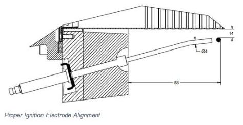
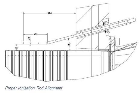
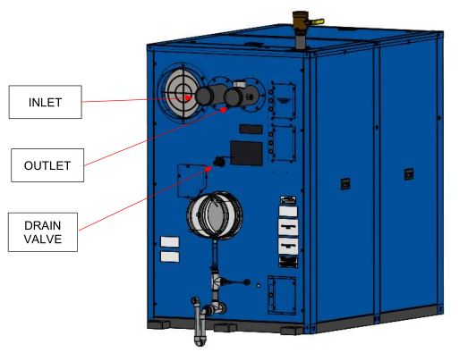
Cleaning the Combustion Chamber
Patterson-Kelley recommends cleaning the combustion chamber once annually using the following procedure:
- Lockout/Tagout gas supply to the boiler.
- Lockout/Tagout electrical power to the boiler.
- Disconnect the condensate piping and install a temporary drain hose into the condensate trap/drain. Run the open end of this hose to a nearby floor drain.
- Make sure the surrounding area is free of obstacles.
- Disconnect the wires to the sensors, switches, ignition electrode, and the ionization rod. Secure the wires out of the way for the following steps.
- Remove the front blower-to-burner transition casting.
- Remove the (6) M8 nuts (13mm head) that secure the casting to the burner door.
- Remove the (2) M8 bolts (13mm head) (on the front) and (2) M8 nuts (13mm head) (on the back) that secure the casting to the blower plate. The transition casting will remain in place, resting on the studs on the burner door.
- Using the handle provided on the casting, remove the casting from the unit, and set to the side. Note the position of the (1) gasket on the top of the casting and the (1) gasket between the casting and the burner door. These gaskets should be replaced when re-installing the casting.
- Remove (8) M14 Door Fixation Screws (12mm Allen) from the perimeter of burner door, that are used to secure the door to the exchanger. Once all screws are removed, the door should be free to slide out of the front of the cabinet.
- Remove the pin located to the left of the door, that locks the hinge in place. Once the pin is removed, the door will be free to rotate about the hinge, providing better access to the inside of the heat exchanger. BE CAREFUL NOT TO DAMAGE THE EQUIPMENT OR THE BURNER, WHICH ARE MOUNTED TO THE DOOR, WHEN ROTATING ON THE HINGE.
- Swing open the burner door/heat exchanger door to provide access to the inside of the heat exchanger. The burner does not need to be removed. Patterson-Kelley does not recommend removing the burner, though it may be removed to provide better access for cleaning the exchanger.
- With the coils to the heat exchanger now accessible, clean the coils with a non-steel brush (preferably nylon). Vacuum out any large debris that is “knocked loose”. ANY CLEANING OF THE COILS WITH ACID OR ALKALI PRODUCTS IS PROHIBITED. However, Patterson-Kelley recommends using a white vinegar solution to assist with the cleaning of the coils. BE SURE NOT TO GET EITHER THE DOOR REFRACTORY, OR THE INNER EXCHANGER REFRACTORY, WET.
- Once the coils have been cleaned, rinse the coils with clean water. BE SURE NOT TO GET EITHER THE DOOR REFRACTORY, OR THE INNER EXCHANGER REFRACTORY, WET.
- Use a pressurized water hose with control nozzle. Begin by spraying just a few seconds of water into the combustion chamber and then close off the nozzle.
- Walk around to the rear of the boiler and ensure the wash water is draining into the temporary drain hose off the condensate drain. Adjust the temporary drain hose if needed to help drain the wash water from the boiler.
- After inspecting the temporary drain hose, continue washing the internal combustion chamber with pressurized water for several minutes. Spray as much of the internal surface area as possible. Be very careful when cleaning to avoid spraying any of the electrical or control components. Water may cause a short circuit and damage circuitry.
- After several minutes of washing, turn off the hose and allow all the wash water to drain from the boiler. Patterson-Kelley recommends rinsing until the water draining from the condensate runs clear.
- Remove the temporary drain hose and reconnect the condensate assembly.
- Reinstall the burner (if applicable).
- Carefully close the burner door and re-insert the pin on the slide.
- Reinstall the burner door studs, finger tightening them in staggered sequence. Once finger tight, torque each stud, in staggered sequence, to 50 Nm/37ft-lbs.
- Reinstall the blower-to-burner transition casting.
- Be sure to have replaced both the top gasket and the burner door gasket.
- Align the studs on the burner door first, and then align the 2 back studs on the blower plate second. Rest the casting on the burner door studs. Verify the gaskets are in the correct positions.
- Install (6) M8 nuts (18ft-lbs/25Nm) to secure the casting to the burner door. Tighten in a staggered sequence.
- Install the (2) M8 studs through the casting to the blower plate. Then install the (2) M8 nuts (18ft-lbs/25Nm) on the back studs.
- Reinstall all wiring that was previously disconnected. (If doing annual maintenance, Patterson-Kelley recommends replacing the ignition cable, ignition electrode, and ionization rod at this time).
- Double check the tightness of all bolted joints and connections.
- Verify that gaskets have been installed in the correct locations.
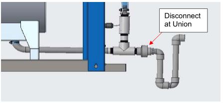
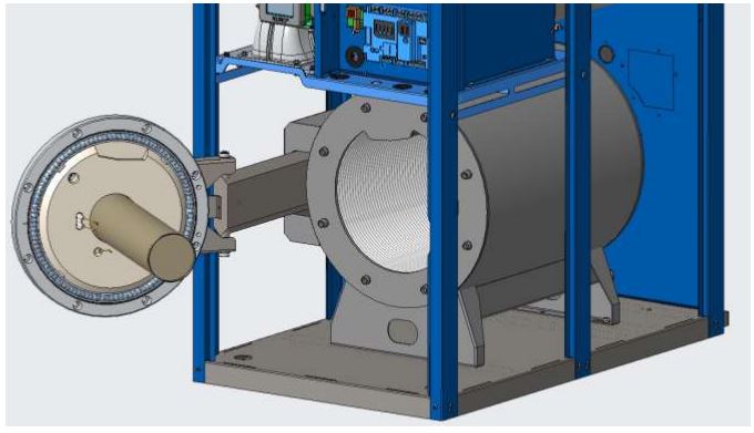
PRECAUTIONS ASSOCIATED WITH HANDLING REFRACTORY LINING MATERIAL
- This Patterson-Kelley product contains a Combustion Area lined with REFRACTORY CERAMIC FIBERS (RCFs) similar to many other devices produced in this industry.
- RCFs have been identified by the International Agency for Research on Cancer (IARC) as possibly being carcinogenic to Humans.
- AVOID breathing particles or dust from RCFs and avoid contact with Skin or Eyes.
- The National Institute for Occupational Safety and Health (NIOSH) recommends the use of a respirator meeting current standards, to avoid inhalation of dust. Also recommended is loose fitting, long sleeved clothing, eye protection and gloves whenever handling RCFs. Current NIOSH Recommendations are listed on their website at http://www.cdc.gov/niosh/homepage.html, which should be viewed before the handling or removal of Refractory Lining Materials on this or any similar device.
- Using a SPRAY BOTTLE, saturate with WATER; but not dripping, the combustion chamber lining to prevent dust from becoming airborne.
- Place removed RCFs into a plastic bag for disposal with normal trash.
- Wash exposed clothing (if not disposable), TWICE and DRY separately from other laundry.
After Repairs or Maintenance
Following any major repairs or preventative maintenance, follow the steps below before returning the boiler to service.
- Follow 3.9 and all safety checks in 3.10.
- Check the gas pressure, refer to 3.11.1 to ensure proper operation of the boiler.
- Perform combustion check (Refer to 3.11.2 through 3.11.4) and adjust air/gas mixture at high fire & low fire if the O 2 % or CO 2 % are out of range.
NOTEInstallation and service must be performed by a qualified installer or service agency that has been trained on the Patterson-Kelley boiler.
Sequence of Operations
- When the Boiler On/Off switch is turned on, power is provided through over-current protection (fuse and/or circuit breaker) to the boiler control and the combustion blower.
- When the outlet water temperature drops below “CH SETPOINT” minus “CH DIFFERENTIAL ON”, a heat request is generated.
- Provided all interlocks are made and the remote enable signal (if installed) is active, the boiler will attempt to start.
- The NURO control checks to make sure air pressure switch is open indicating there is no airflow through the boiler. The combustion blower is then driven towards the pre-start fan speed. When the air pressure switch closes, the “PREPURGE TIME” timer is started. Once the “PRE PURGE TIME” timer expires, the blower is driven to the ignition speed.
- A trial for ignition begins and the sequence of events is illustrated graphically below. A valid flame signal must bedetected within 4 seconds after the gas valves open (elapsed time 7 seconds).
- After a successful ignition, the fan is driven to low fire and the “CH LOW FIRE HOLD TIME” timer is started. Once the “LOW FIRE HOLD TIME” timer expires, the boiler is released to modulation.
- The NURO Control modulates the firing rate between low and high fire to maintain the desired outlet water temperature.
- The burner will continue firing until the outlet water temperature exceeds “CH SETPOINT” plus “CH DIFFERENTIAL OFF”. At this temperature, the gas valves are closed combustion air fan continues to run until the “POST PURGE TIME” timer has expired.
- When the outlet water temperature is reduced by the load on the system, a heat request is generated. The operating sequence will recycle to Step 3.
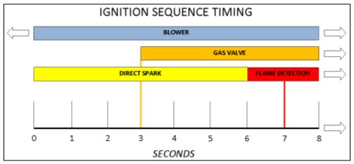
If any “Manual Reset” limit device trips, DO NOT reset without determining and correcting the cause. Manual Reset Limitsinclude: Flame safeguard, high or low gas pressure, high temperature limit, stack temperature, low water level. Attempting to operate a boiler without diagnosing the cause of failure can result in unsafe operation, increasing the risk of injury. Never attempt to bypass a safety limit device.
NOTICE ! Once the boiler begins the ignition sequence, the firing sequence will continue until main flame is reachedregardless of heat request. The sequence can be interrupted by turning the power switch off.
Troubleshooting
The NURO control will display graphical and/or text based error descriptions to announce any problems with the boiler. There are two types of lockouts: manual reset lockouts which require the operator to physically press the on-screen or device’s reset button, and automatic reset lockouts which will self-reset when the error condition clears. For a comprehensive list of errors and potential resolutions, please refer to the NURO Advanced User’s Guide. Should the unit fail to operate, call a qualified service technician to troubleshoot the problem and implement corrective actions.
Loss of Power
In the event of a power failure, the NURO touch screen will go dark and the entire boiler will de-energize. The signal relays used to command auxiliary devices connected to the boiler (air dampers, pumps, etc.) will also lose power, so these devices will deactivate. When power is restored, the sequence of operation will resume at Step 3 (5.4). If any error/lockout errors were present at the time of the power failure, the NURO control will retain that error/lockout when power is restored.
Loss of Water Level
The low water switch opens when there is an insufficient water level in the boiler. The NURO control will display 10010: “Low Water Limit”, close the gas valve, and lock the boiler out. When the water level is corrected and the on-screen reset button is pressed, the boiler will reset and resume the sequence of operation at Step 3 (5.4).
Low Gas Pressure
The low gas pressure switch opens when there is (or has been) insufficient gas pressure available for proper operation of the boiler. If an external gas-supply shut-off valve is closed for any reason, a low gas condition will result. The NURO control will display 10012: “Low Gas Limit”, close the gas valve, and lock the boiler out. When proper gas pressure is restored, and the on-screen reset button is pressed, the boiler will reset and resume the sequence of operation at Step 3 (5.4).
High Gas Pressure
The high gas pressure switch opens when there is (or has been) excessive gas pressure for the proper operation of the boiler. The NURO control will display 10011: “High Gas Limit”, close the gas valve, and lock the boiler out. When proper gas pressure is restored, and the on-screen reset button is pressed, the boiler will reset and resume the sequence of operation at Step 3 (5.4).
High Water Temperature
When the boiler water has exceeded both the operating temperature limit and the manual reset high-temperature limit, the NURO control will display 10009: “High Temperature Limit”, close the gas valve, and lock the boiler out. When the water temperature falls below the high-limit temperature setting, the boiler will remain locked out until the water high-temperature limit switch is manually reset and the on-screen reset button is pressed. Once reset, the control will resume the sequence of operation at Step 3 (5.4).
Low Air
If the NURO control displays either 65: “Interrupted Airflow Switch OFF” or 66: “Interrupted Airflow Switch ON” , this indicates improper airflow through the boiler. First, verify proper standby blower operation – when the boiler is in “Standby”, the blower should also be in standby.
Next, check for obstructions of the combustion air intake and/or exhaust (flue) piping. Next, check the hoses leading to the air switches are not kinked or obstructed. An error related to the air switch does not necessarily mean that the air switch is defective.
When 66: “Interrupted Airflow Switch ON” is displayed, check that the air switch is open when the blower is offline. Ensure there is no air flow through the boiler when the blower is offline. An excessive negative draft in the flue piping can cause air flow through the offline boiler which may be strong enough to maintain closure of the air switch.
When 65: “Interrupted Airflow Switch OFF” is displayed, check that the air switch is closed when the blower is running. If the air switch does not close within 5 minutes during purge, the boiler locks out. Check that the burner is clean (Refer to Section 5.2) and that there are no obstructions to airflow in the intake or exhaust ducts.
Flame Failure
In the event of a flame failure, the NURO control may display one of the following error messages:
- 106: “Flame Lost in Main Flame Establish Period”
- 107: “Flame Lost Early in Run”
- 108: “Flame Lost in Run”
- 109: “Ignition Failed”
- 110: “Ignition Failure Occurred”
When 109: “Ignition Failed” or 110: “Ignition Failure Occurred” is displayed, the boiler did not light during the trial for ignition. Check that the ignition electrode, ignition wire, and gas valve are functioning properly. Check that the direct spark ignition is visible through the flame observation port during the trial for ignition.
When 106: “Flame Lost in Main Flame Establish Period”, 107: “Flame Lost Early in Run”, or 108: “Flame Lost in Run” is displayed, the boiler lost the flame signal during operation. Check that combustion is adjusted properly, the gas pressure is correct, and the ignition electrode, ignition wire, and gas valve are functioning properly.
Flame Error
In the event of a flame error (premature or late flame signal), the NURO control will display 105: “Flame Detected Out of Sequence”. This may be caused by a failed/leaky gas valve or a flame rod or ionization rod malfunction. If gas valve leakage is suspected, the unit must be isolated by turning off the main gas supply line. Lockout/Tagout the boiler until qualified and knowledgeable service personnel are available to evaluate and repair or replace the failed parts. Check that the incoming gas pressures have not exceeded 14” W.C. (1/2 psig).
Flue Problem/Condensate Blockage
When the normally-closed high exhaust back pressure switch opens, the NURO control will display 10249: “High Back Pressure In Stack or High Condensate Level”. This may be caused by an obstruction in the flue piping or an obstruction in the combustion air intake.
The same error is displayed for a blocked condensate system. This may indicate that the level of the condensate is above the probe in the condensate piping. When the blockage is removed and the condensate drains freely, the boiler will automatically restart.
If no blockages are found, it may be necessary to replace either the high exhaust back pressure switch or the Condensate Blockage System.
Parts/Technical Support
Spare parts and replacement parts can be ordered from Patterson-Kelley by calling toll free (877) 728-5351. Reach us by fax at (570) 476-7247.
Refer to the parts list shown on the assembly drawings provided in this manual.
Technical information is also available by calling or visit the Patterson Kelley website, www.pattersonkelley.com.
When ordering replacement parts please have the model number and serial number of your boiler available. Typical schematic drawings are shown on the following pages. Drawings specific to your particular boiler can also be supplied by your local Patterson-Kelley representative.
Use of Non-Factory Authorized replacement parts are not recommended for this equipment. All control components are engineered for safety and are designed to work in unison with each of the other components. Use of non- factory authorized replacement parts jeopardizes the functionality of the safety features as well as the performance of the boiler.
Terminal Block Assignments
Terminal Block Assignments — Low Voltage (TB1) Terminal Block
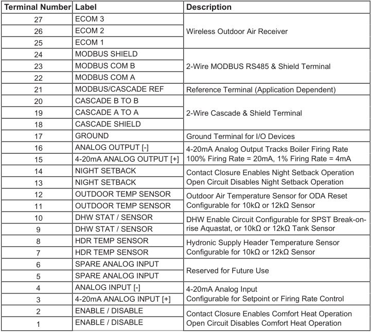
Terminal Block Assignments — High Voltage (TB2) Terminal Block
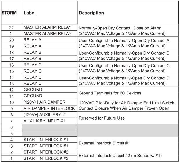
Wiring Diagrams
Natural Gas 208-240 Volt
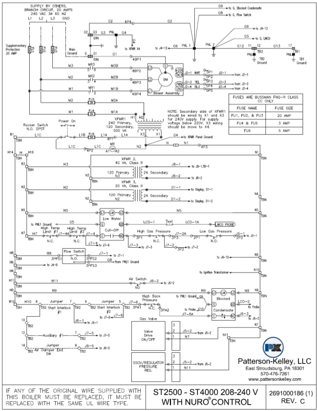
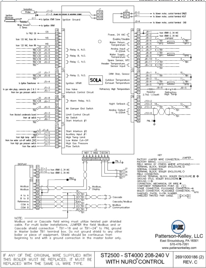
Natural Gas 480 Volt
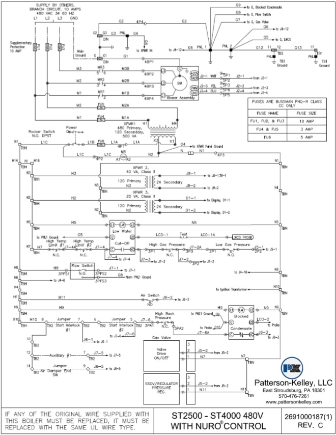

Control Transformer Diagrams
208 VAC, Three Phase, 60 Hz
![]()
220-240 VAC, Three Phase, 60 Hz
![]()
440-480 VAC, Three Phase, 60 Hz
![]()
Before making any electrical connections to the boiler, verify that the control transformer is properly configured for the applicable incoming power supply to the boiler:
- 208V, three phase, 60Hz
- 220-240V, three phase, 60Hz
- 440-480V, three phase, 60Hz
Improper configuration of the control transformer could result in serious injury or death.
Boiler Parts Identification
Main Boiler Assembly (ST-2500 & ST-3000)
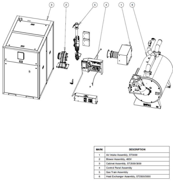
Main Boiler Assembly (ST-3500 & ST-4000)
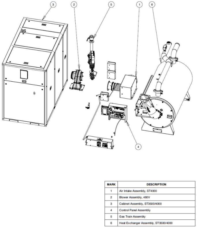
Control Panel
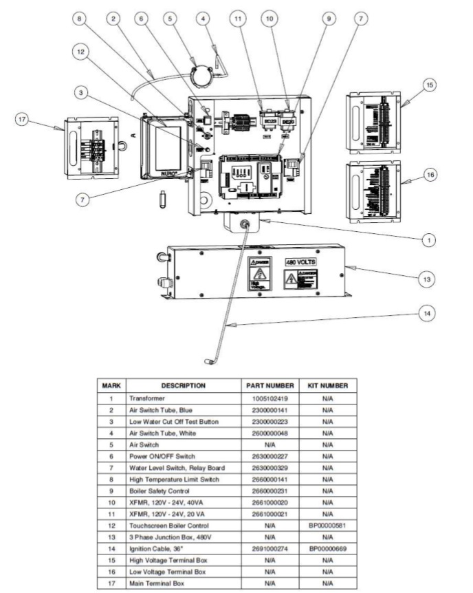
Heat Exchanger Assembly ST-2500 & ST-3000
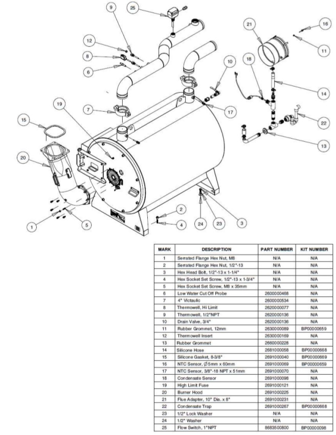
Heat Exchanger Assembly ST-3500 & ST-4000
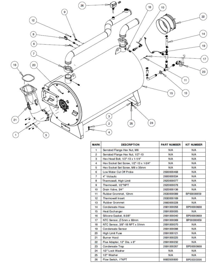
Natural Gas Train

Burner/Blower Assembly 240V
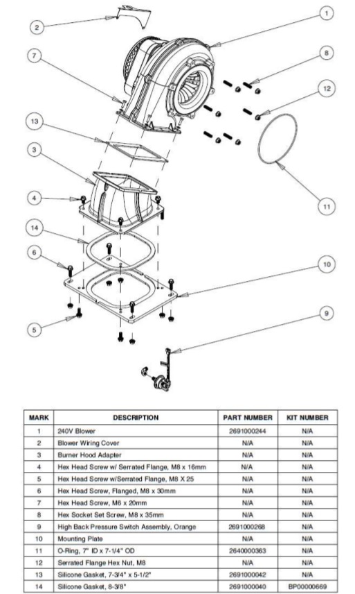
Burner/Blower Assembly 480V
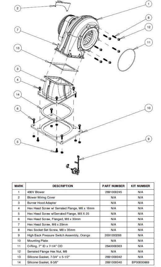
P-K STORM ™ SPECIFIC LIMITED WARRANTY
Last Updated 12/12/2016Subject to the terms and conditions herein and the Terms and Conditions of Sale (as defined herein), Patterson-Kelley (“Seller”) warrants to the purchaser of the product (“Buyer”) that the heat exchanger and burner are free of defects in material and workmanship, when operated in accordance with the conditions stated herein, for a period of ten (10) years for the heat exchanger, five (5) years for the burner and a ten (10) year warranty against failure due to thermal shock commencing on the date of shipment or, if a start-up report is furnished to Seller, on the start-up date shown on the report furnished to Seller (the “Warranty Period”), provided that startup is completed within six (6) months of shipment and the start-up report is furnished to Seller within thirty (30) days of startup (this “Specific Limited Warranty”). The Exclusions and limitations of liability set forth in the Terms and Conditions of Sale (as defined herein) apply to this Specific Limited Warranty. Capitalized terms used but not defined herein have the meanings ascribed to them under Seller’s terms and conditions of sale for the product, which can be found at http://pattersonkelley.com/warranty.php (the “Terms and Conditions of Sale”). This Specific Limited Warranty is transferrable to the owner that utilizes the product(s) purchased hereunder for its intended use at the original installation site (the “Original Owner”). This Specific Limited Warranty is non-transferable to anyone who subsequently receives or purchases products from the Original Owner. If the Original Owner did not purchase the product directly from Seller, the Original Owner should contact the reseller from whom it purchased the product for a copy of the Terms and Conditions of Sale attached to the Order Acknowledgement received by the original purchaser of the product from Seller.
- REMEDYSeller’s obligations under this Specific Limited Warranty is limited to repairing or, if in Seller’s judgment it seems more appropriate, to furnishing without charge (installation not included), FCA Seller’s factory (Incoterms 2010), a similar part to replace any part which after examination shall, to Seller’s own satisfaction be determined to have been defective at the time it was shipped. In the event that a replacement is provided by Seller, the defective item will become the property of Seller. Transportation to Seller’s facility or other designated facility for repairs of any products or party alleged defective shall, in all events, be at Buyer’s sole risk and cost. This warranty applies only if the original installer and Seller (Attention: Patterson-Kelley, 155 Burson Street, East Stroudsburg, PA 18301) receive, within the Warranty Period, an immediate written notice, providing a detailed description of all claimed defects, upon discovery of such defects together with proof of purchase (invoice or Order Acknowledgment) and a copy of the start-up report for the affected product. Seller may seek reimbursement of any costs incurred by Seller where the product is found to be in good working order, or when it has been determined that this Specific Limited Warranty does not apply as per the exclusions set forth below. The remedies available to Buyer set forth herein are exclusive remedies, and all other remedies, statutory or otherwise, including but not limited to the right of redhibition, are waived by Buyer. Buyer acknowledges that the exclusion of remedies is neither unreasonable nor unconscionable. Buyer shall indemnify and hold Seller harmless against, any claim due to any injury or death to any person or damage to any property resulting in whole or in part from any modification or alteration Buyer makes to any product sold hereunder.
- EXCLUSIONSTo the full extent permitted by law, Seller shall have no liability for and the Warranties do not cover:
- any product which has been altered or repaired by other than Seller’s personnel;
- deterioration or failure of any product due to
- abrasion, corrosion, erosion or fouling,
- misuse,
- modification not authorized by Seller in writing or
- improper installation, lack of or improper maintenance or operation;
- equipment not furnished by Seller by the owner, either mounted or unmounted, or when contracted for by a party or parties other than Seller to be installed or handled;
- the suitability of any product for any particular application;
- the design or operation of owner’s plant or equipment or of any facility or system of which any product may be made a part;
- any damage to the product due to abrasion, erosion, corrosion, deterioration, abnormal temperatures or the influence of foreign matter or energy;
- the performance of any product under conditions varying materially from those under which such product is usually tested under industry standards at the time of shipment;
- leakage or other malfunction caused by:
- defective installations in general and specifically, any installation which is made
- in violation of applicable state or local plumbing, housing or building codes or
- contrary to the written instructions furnished with the product,
- adverse local conditions in general and, specifically, sediment or lime precipitation in the tubes, headers and/or shells or corrosive elements in the water, heating medium or atmosphere, or
- misuse in general and, specifically, operation and maintenance contrary to the written instructions furnished with the unit, disconnection, alteration or addition of components or apparatus, not approved by Seller, operation with heating media, fuels or settings other than those set forth on the rating plate or accidental or exterior damage;
- defective installations in general and specifically, any installation which is made
- production of noise, odors, discoloration or rusty water;
- damage to surrounding area or property caused by leakage or malfunction;
- costs associated with the replacement and/or repair of the unit including: any freight, shipping or delivery charges, any removal, installation or reinstallation charges, any material and/or permits required for installation, reinstallation or repair, charges to return the boiler and/or components;
- INCIDENTAL, SPECIAL OR CONSEQUENTIAL DAMAGES, SUCH AS LOSS OF THE USE OF PRODUCTS, FACILITIES OR PRODUCTION, INCONVENIENCE, LOSS OF TIME OR LABOR EXPENSE INVOLVED IN REPAIRING OR REPLACING THE ALLEGED DEFECTIVE PRODUCT;
- any claim due to any injury or death to any person or damage to any property resulting in whole or in part from any modification or alteration Buyer makes to any product sold hereunder; and
- Design defects where Seller has complied with Buyer’s design specifications.
- PROOF OF PURCHASEProof of purchase (invoice or Order Acknowledgement) and a copy of the start-up report for the affected product must be provided to Seller when requesting service under this Specific Limited Warranty.
- ORDER OF PRECEDENCEThe Standard Limited Warranty set forth in the Terms and Conditions of Sale, (b) this Specific Limited Warranty and (c) any applicable Extended Limited Warranty exclusively govern and control Seller’s and Buyer’s respective rights and obligations regarding the warranty of the product. In case of any inconsistency, conflict, or ambiguity between the Standard Limited Warranty, this Specific Limited Warranty and any applicable Extended Limited Warranty (collectively, the “Warranty Documents”), the documents shall govern in the following order: (w) any applicable Extended Limited Warranty; (x) this Specific Limited Warranty; (y) the Standard Limited Warranty and (z) other provisions in the Terms and Conditions of Sale. Information identified in one Warranty Document and not identified in another shall not be considered a conflict or inconsistency. No sales representative, agent, or employee of Seller or any reseller in the chain of sale of the product is authorized to make any modification, extension, or addition to this Specific Limited Warranty, unless agreed to in writing by Seller.
Boiler Fire-Test Report
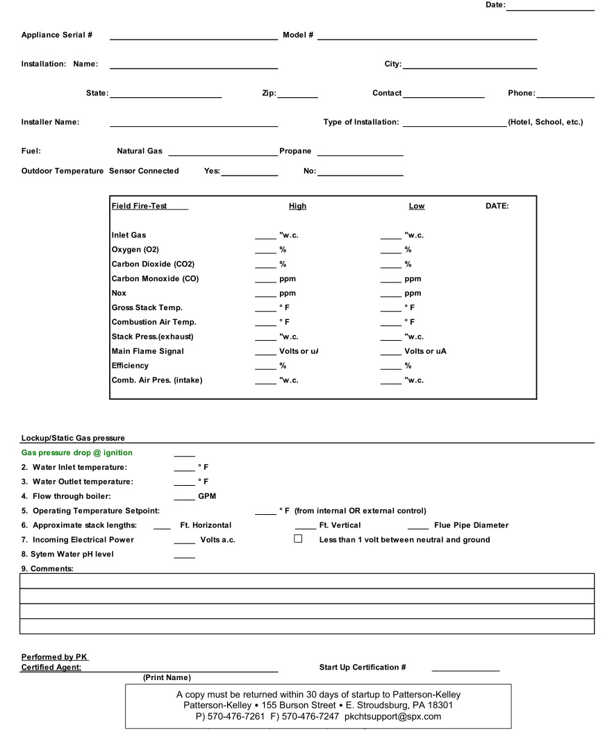
Appendix A – Maintenance Log
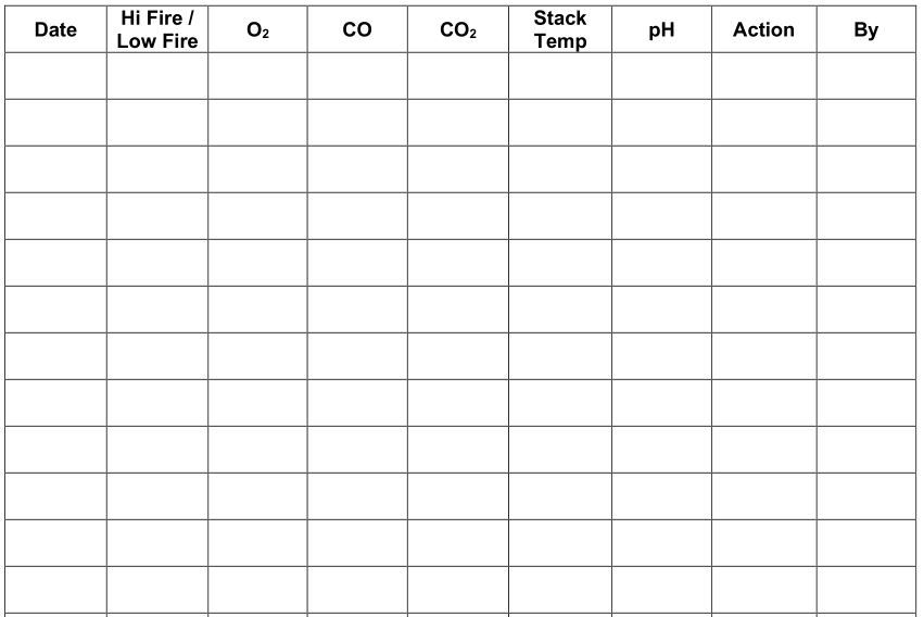
Appendix B – Boiler Altitude Derate Schedule
For installations over 2,000 ft. elevations, a derate schedule is applied. The boiler input rating must be reduced by 4% per 1,000 ft. which is illustrated in the graph below.
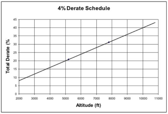
Although the appliance’s capacity is reduced due to the lower air density, the combustion tuning should follow the standard combustion guidelines of 3.11. Tune the combustion for the same O 2 and CO 2 levels as discussed in 3.11.2.
Appendix C – Water Quality Standards Quality Standards for Hydronic Boilers in Multi-Metal Systems
Patterson-Kelley boilers are designed to be incorporated into any multi-metal hydronic heating system. All multi-metal hydronic systems require that attention be paid to water treatment. The chemical additives for any multi-metal system must be specifically formulated for use with all the various metals used in that system.
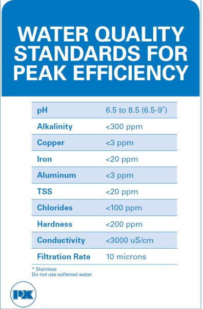
Any closed, hydronic heating systems should include a meter, to monitor water addition to the recirculating loop, and a filter, pursuant to ASHRAE Standard 189.1 and the AWT Handbook. Water added to a closed hydronic system should not exceed more than 10% of the system volume per year and meter readings should be recorded, at least monthly, to ensure system losses are minimized and corrective actions shall be taken when needed.
Treatment programs for multi-metal systems should meet or exceed the following generally accepted best practices water quality guidelines: Prior to initiating any treatment program, a water sample of the proposed fill water should be sampled for analysis. Once filled and bled of air, a pH neutral, industrial cleaner for use in multi-metal systems should be used to clean the entire hydronic system. Samples of the system water with cleaner should be taken and analyzed to ensure proper cleaner strength. Once cleaned, the system should be flushed with fresh (fill) water until the system water is within 100 micro Siemens in conductivity of the fresh water. When flushing is complete, a treatment program that is designed for use in that multi-metal system, after consideration of the metals it contains, must be used. Treatment programs should also comply with the standard water quality guidelines listed above.
Appendix D – Best Practices For New & Retrofit Systems
BEST PRACTICES FOR ALL BOILER INSTALLATIONS
- Patterson-Kelley recommends and most installation codes require isolation valves on both the boiler’s inlet (return) and outlet (supply) pipe runs. These are used to hydraulically isolate the boiler from the hydronic system, which should be standard practice when flushing or adding concentrated cleaning chemicals.
- Patterson-Kelley recommends installing purge valves on the system side of the boiler’s isolation valves. These valves should be used to purge the hydronic system of debris and sediment prior to the initial startup of the boiler equipment. Since the purge valves are located on the system side of the boiler’s isolation valves, the debris and sediment will not be routed in direct proximity to the boiler’s heat exchanger.
- Patterson-Kelley recommends installing a standard mesh strainer (maximum 20 mesh) on each boiler’s return (inlet) piping. This is intended to prevent large particles, foreign debris, etc. from entering and obstructing flow or heat transfer through the boiler’s heat exchanger. Each strainer should feature a manual blow-down valve in order to purge the debris from the strainer. NOTE: This strainer is not intended to remove fine particulate matter from the boiler system which will be discussed later in this appendix.
- Patterson-Kelley recommends installing a water meter on the cold water fill piping. The intention of this device is to periodically monitor the amount of fresh water introduced into the system piping. It can also be used to establish a rough estimate of the total system volume during the initial fill. In general, the annual amount of fresh water make-up should be less than 10% of the total system volume. A water meter can also be useful to detect a leak in the hydronic system if you notice an unexpected increase in the volume of fill water.
- Oxygen (O 2 ) elimination is critical to the longevity of any hydronic system. Patterson-Kelley recommends installing an Air Separator (micro-bubbler style) that is capable of eliminating the dissolved Oxygen levels introduced from the cold water fill. In general, air separators are most effective when the boiler water is at highest temperature and lowest pressure.
- Patterson-Kelley recommends installing an Automatic Air Vent on the Air Separator. In order for the Air Separator to continually purge the system of dissolved Oxygen, an Automatic Air Vent is preferred over a manual air vent.
- The maximum flow rate requirements vary between Patterson-Kelley boiler models. Please refer to Appendix E – Installation and Quick Reference for a complete listing of the maximum flow rates per boiler model. Exceeding the maximum flow rate of a boiler can cause erosion of the boiler’s heat exchanger or piping materials and can damage the paddle type flow switch.
- The minimum flow rate requirements vary between Patterson-Kelley boiler models. Please refer to Appendix E – Installation and Quick Reference for a complete listing of the minimum flow rates per boiler model. Flowing below the minimum flow rates can lead to overheating of the boiler’s heat exchanger materials and the formation of steam bubbles within the water passages.
- Well in advance of the equipment startup, turn off all circulation pumps and close the isolation valves on each boiler’s inlet (return) and outlet (supply) pipe runs. Connect a hose to the purge valves and run this hose to a nearby floor drain. Open each purge valve to flush out debris that is present in the water. This process may take several attempts until the discharge water is sufficiently clean. After successfully purging the system, make sure to open the boiler’s isolation valves and turn on the circulation pumps.
- Upon startup, Patterson-Kelley recommends collecting two water samples: one from the hydronic system and another from the cold water fill. It is best practice to circulate the hydronic system for at least one hour prior to collecting this initial water in order to acquire a representative (blended) sample.
- Within the first three months after startup, Patterson-Kelley recommends collecting a follow-up water sample from the hydronic system. This should be compared to the initial startup sample in order to determine any changes in pH, Alkalinity, conductivity, etc. that may adversely affect the system performance.
- Although the ongoing water treatment regimen will vary based on the supplier and application, Patterson-Kelley recommends a minimum annual water sample rate. The results of the annual water tests should be compared to past tests in order to determine any changes in pH, Alkalinity, conductivity, etc. that may adversely affect the system performance. Refer to Appendix C – Water Quality Standards Quality Standards for Hydronic Boilers in Multi-Metal Systems for the water quality standard.
BEST PRACTICES FOR RETROFIT BOILER INSTALLATIONS
- The primary concern in retrofit installations into existing boiler systems is the presence of suspended and dissolved solids. These are typically a result of deteriorating piping, fittings, or legacy boiler’s heat exchangers. Patterson-Kelley recommends installing a side-stream filter (maximum 10 micron) to remove this existing particulate, sediment, etc. There are many different types of side-stream filters available. Patterson-Kelley recommends consulting your local water treatment provider to determine the best method for your particular application.
- If the existing hydronic system contains a significant amount of suspended and dissolved Iron, Patterson-Kelley recommends the use of a side-stream filter with built-in magnet. This magnet helps attract and eliminate the Iron particulate.
- Some water treatment additives/chemicals may cause leeching from the existing system piping. As more contaminants leech from the walls of the piping into the system water, the pH and the level of Total Dissolved Solids (TDS) may gradually climb to levels that will adversely affect the system performance. A side-stream filter will accommodate the increased TDS, but you may need to consult your local water treatment provider in order to combat the increased pH.
BEST PRACTICES FOR NEW BOILER INSTALLATIONS
- The construction of the hydronic system piping involves many different operations that can introduce contaminants (weld slag, solder, flux, pipe dope, cutting oils, metal shavings, etc.) It is critical to properly flush the system well in advance of startup of the boiler equipment.
- In order to locate loose pipe connections, leaks, etc. after the initial construction of the hydronic system piping, the Mechanical Contractor may fill and drain the system several times. During these initial fill-ups and drains, Patterson-Kelley recommends closing the boiler’s isolation valves in order to separate them from the hydronic system. This will help limit the amount of dissolved Oxygen and particulates that are brought in direct contact with the boiler’s heat exchanger.
Appendix E – Installation and Quick Reference
Fuel/Gas Supply
- Refer to 3.7 for information on proper sizing of the gas supply piping. Undersized gas piping with too much pressure drop will negatively impact the boiler’s performance.
- Install a lock-up type gas regulator to supply an appropriate gas pressure as described below:
Natural GasMinimum Inlet Pressure = 4.0” W.C .Maximum Inlet Pressure = 14.0” W.C.
NOTE: Patterson-Kelley recommends installing an individual lock-up type gas regulator in the gas supply piping to each boiler. For installations where one master lock-up type gas pressure regulator will service multiple boilers, Patterson-Kelley recommends contacting the local regulator representative for application assistance specifying the appropriate lock-up type regulator and gas pipe sizing.
Electrical/Power Supply
- Carefully inspect the boiler’s nameplate labels which describe the power supply requirements.
- Provide an appropriate power feed to the boiler with overcurrent protection:
- Prior to startup, carefully check all electrical connections for tightness as connections can come lose during shipping.
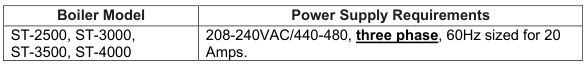
Exhaust Venting
- The P-K STORM boilers are dual-certified as Category II & Category IV appliances, capable of operating with slightly negative to slightly positive exhaust pressure. It is critical to ensure the flue venting material is suitable for use with the boiler.
- For Category II installations, ensure the flue venting system is designed to maintain a slightly negative exhaust pressure between -0.01” W.C. and -0.05” W.C.
- For Direct Vent / Sealed Combustion Category IV installations, ensure the flue venting system is designed to maintain a slightly positive exhaust pressure between +0.01” and +0.22” W.C.
- For Exhaust Only Category IV installations, ensure the flue venting system is designed to maintain a slightly positive exhaust pressure between +0.01” and +0.4” W.C.
The chart below represents the pressure drop (Ft of Head) versus the water flow rate (GPM) for the P-K STORM ST-2500 through ST-4000. This information is useful to help size an appropriate circulation pump. Keep in mind this pressure drop represents the boiler only, additional consideration is needed for any connecting piping, valves, strainers, couplings, flanges, etc.
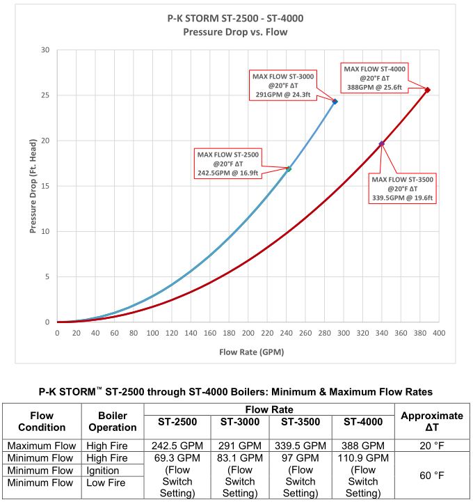
Propylene Glycol Flow
The table below summarizes the flow for the P-K STORM appliances with different Propylene Glycol mixtures:
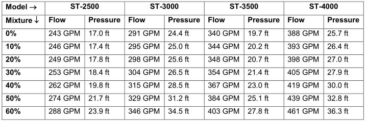
Patterson Kelley P-K Storm Gas Fired Boiler User Manual – Patterson Kelley P-K Storm Gas Fired Boiler User Manual –
[xyz-ips snippet=”download-snippet”]