Installation Manual
Emma ChandelierAssembly and Installation InstructionsCountry of Destination: US/CN UK/EU/AUS Middle EastCAUTION:
- BEFORE INSTALLING FIXTURE, MAKE SURE THE POWER TO THE CIRCUIT IS TURNED OFF AT THE MAIN FUSE BOX / CIRCUIT BREAKER UTILITY BOX.Important Safety Instructions:
- These instructions are provided for your safety. It is very important that they are read carefully and completely before beginning the assembly and installation of this lighting fixture.
- We strongly recommend that a professional electrician install all direct wire fixtures.
- THIS PRODUCT MUST BE INSTALLED IN ACCORDANCE WITH THE APPLICABLE INSTALLATION CODES BY A PERSON FAMILIAR WITH THE CONSTRUCTION AND OPERATION OF THE PRODUCT AND THE HAZARDS INVOLVED.
- The lighting fixture is meant for indoor use. It must be connected only to 3-wire, single-phase electrical supply systems (provided with Ground wire or equivalent protection system).
- For your safety, it is strongly recommended that two people install the lighting fixture.
- This fixture has been rated for up to four (4) 40-watt maximum Type B standard (candelabra) incandescent light bulbs (not included) or four (4) 9-watt compact fluorescent light bulbs (not included). To avoid the risk of fire, do not exceed the recommended lamp wattage.
- Use with approved PBteen Shades only, having a minimum opening diameter of 3-1/2 inches and a minimum lamp-to-shade spacing of 2 inches.
- The lighting fixture is meant for indoor use, DRY LOCATIONS ONLY.
- Save these instructions.WARNING:
- To reduce the risk of fire, electrical shock or personal injury, always turn off and unplug the light fixture and allow it to cool prior to replacing the light bulb.
- Do not touch bulb when fixture is turned on. Do not look directly at lit bulb.
- Keep flammable materials away from lit bulb.
- This lighting fixture contains lead, a chemical know to the State of California to cause cancer, birth defects and other reproductive harm. Wash hands after installing, handling, cleaning or otherwise touching this light fixture.Pre-assembly:
- Remove all parts and hardware from box along with any plastic protective packaging.
- Do not discard any contents until after assembly is complete to avoid accidentally discarding small parts or hardware.
- For your safety, it is strongly recommended that two people install the lighting fixture.
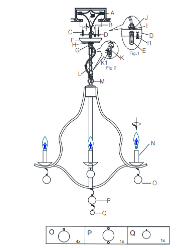
Parts Included: Hardware Enclosed:(1) Mounting Plate (D) (3) Plastic Wire Nut Connectors (A)(1) Threaded Tube (E) (1) Green Ground Screw (B)(1) Canopy (F) (2) Mounting Screws (C)(1) Hanging Loop (G) (4) Big Metal Balls (O)(1) Canopy Nut (H) (1) Big Metal Ball (P)(1) Lock Washer (I) (1) Small Metal Ball (Q)(1) Hex Nut (J)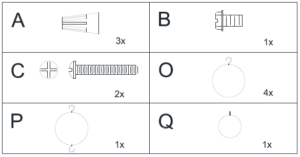 (2) Closable Link with Screw Cap (K/K1)(1) Chain (L)(1) Fixture Loop (M)(4) Sockets (N)
TOOLS REQUIRED (not included): Ladder, Phillips Head & Flat Blade Screwdrivers, Wire Cutter/Stripper, Pliers &Electrical Tape.
To Adjust the Suspension Length of the Fixture:
- Note: The adjustment or shortening of the lighting fixture’s suspension length is only needed if the factory set chainlength is not appropriate for your installation. We recommend that you adjust the chain to the proper desired lengthbefore cutting the electrical cord.
- Determine the lighting fixture suspension length from the ceiling for the product installation, allowing the extra cordlength for the outlet junction box wire connections as noted below.
- Pull out the fixtures 2 wire power cord and bare ground wire woven through the Chain (L).
- The chain length may be shortened from either end, if desired, by using pliers to separate a link along a split-lineformed in each link. Use two pairs of pliers to gently pry the link apart so that a space is created large enough for thelink to be removed from the remaining chain. Use a cloth or folded piece of paper between the pliers and the link toprotect the finish of the link during bending. For longer lengths of chain to be removed, select the desired link fromeither end to open and remove the length of chain. Once the chain is at the desired length, reattach the chain (if itisn’t already) to the two Closable Links with Screw Caps (K) at each end of the chain. Secure each link by tighteningthe Closable Link Screw Cap (K1) (See Fig. 2). One Closable Link with Screw Cap (K) must be attached to both theChain (L) and Fixture Loop (M) at the top of the Pendants Body and the other Closable Link with Screw Cap (K)must be securely attached to the other end of the Chain (L) and Hanging Loop (G).
- Re-weave the fixtures 2 wire power cord and bare ground wire through every other loop to the top of Chain (L).
- If needed, (depending upon final fixture hanging position from the ceiling), cut off the extra power cord length on the2 wire cord and bare ground wire. Make sure when cutting the power cord and bare ground wire to cut them so thatthey all are at least 6 inches (152.4 mm) long within the outlet junction box (J-box). Prepare the cut power cord wiresusing the following steps. Use wire strippers to prepare the ends of the two wires so that there is about 1/2 inch ofexposed wire for the Plastic Wire Nut Connectors (A).
Assembly & Installation Instructions:
- SHUT OFF THE MAIN ELECTRICAL SUPPLY FROM THE MAIN FUSE BOX/CIRCUIT BREAKER!
- Carefully unpack all fixture parts and hardware and lay them out on a clear workspace.
- Unscrew the Closable Link Screw Cap (K1) from the lower Closable Link (K), and insert the bottom loop of Chain (L)and Fixture Loop (M) into the Closable Link (K). Tighten the Closable Link Screw Cap (K1) as shown in Fig. 2.4. If needed, weave the fixtures 2 wire power cord and bare ground wire through every other loop to the top of Chain(L).
- Slip Canopy Nut (H) first and then position Canopy (F) over the upper end of Chain (L).
- Unscrew the Closable Link Screw Cap (K1) from the upper Closable Link (K), and insert the top loop of Chain (L)and Hanging Loop (G) into the Closable Link (K). Tighten the Closable Link Screw Cap (K1) as shown in Fig. 2.
- If the parts are not already preassembled, attach the Threaded Tube (E) into the threaded bore of the Hanging Loop(G) and rotate the Threaded Tube (E) clockwise until it is tightly engaged within the Hanging Loop (G). If theThreaded Tube (E) is not yet secured to the Mounting Plate (D), do so now so that a portion of the Threaded Tube (E)extends beyond the Mounting Plate (D).
- Position the Lock Washer (I) first and then the Hex Nut (J) onto the extended upper portion of the Threaded Tube (E).Make sure the length of the Threaded Tube (E) is longer on the bottom end, as shown in Fig. 1. Tighten the Hex Nut(J) until tight using a hex wrench or a pair of pliers so that the Hanging Loop (G) is now firmly secured to the middleof the Mounting Plate (D).
- Feed the fixtures 2 wire power cord and bare ground wire through to the Hanging Loop (G) and the Threaded Tube(E).
- If needed, (depending upon final fixture hanging position from the ceiling), cut off the extra power cord length on the2 wire cord and bare ground wire. Make sure when cutting the power cord and bare ground wire to cut them so thatthey all are at least 6 inches (152.4 mm) long within the outlet junction box (J-box). Prepare the cut power cord wiresusing the following steps. Use wire strippers to prepare the ends of the two wires so that there is about 1/2 inch ofexposed wire for the Plastic Wire Nut Connectors (A).
- Gently pull existing wire down from the ceiling junction box and allow wires to hang. The HOT or LIVE wire is usuallyblack. The NEUTRAL wire is usually white. Check to see if there is a ground wire that is usually green or green witha yellow stripe or exposed copper metal wire. If needed, use a pair of wire strippers to remove about 1/2 inch ofinsulation from each wire.
- Carefully inspect the fixtures wires. The NEUTRAL FIXTURE WIRE has FINE LONGITUDINAL RIDGES runningalong its length. The HOT FIXTURE WIRE is SMOOTH and the BARE COPPER WIRE is the GROUND WIRE. Ifyou have any doubt and cannot identify the power-supply wires with confidence, then we recommend that you askan electrician and that you not continue with the installation.
- With the help of another person to hold the weight of the fixture, attach the GROUND WIRE from the fixture to theGROUND JUNCTION BOX WIRE from the ceiling outlet junction box (J-box) (usually green insulation or bare wire).Fasten each together with a Plastic Wire Nut Connector (A) by twisting the connector in a clockwise direction andwrap the connection with electrical tape. Be sure that no wire strands are exposed. If your outlet junction box DOESNOT have a GROUND WIRE, be sure to insert the Green Ground Screw (B) into the Mounting Plate (D), marked as“GND”, facing downward and wrap the fixture’s bare ground wire around the Green Ground Screw (B). Tightenscrew to clamp ground wire between ground screw head and Mounting Plate (D). IT IS IMPERATIVE THAT THEJUNCTION BOX IN YOUR HOME BE PROPERLY GROUNDED!
- Connect the NEUTRAL FIXTURE WIRE to the NEUTRAL JUNCTION BOX WIRE (usually white insulation). Fasteneach together with a Plastic Wire Nut Connector (A) by twisting the connector in a clockwise direction and wrap theconnection with electrical tape.
- Be sure that no wire strands are exposed.
- Connect the HOT FIXTURE WIRE to the HOT JUNCTION BOX WIRE (usually black insulation). Fasten each together with a Plastic Wire Nut Connector (A) by twisting the connector in a clockwise direction and wrap the connection with electrical tape. Be sure that no wire strands are exposed. DO NOT REVERSE THE HOT ANDNEUTRAL CONNECTIONS OR SAFETY WILL BE COMPROMISED.
- Check the wiring connections and if all looks good, gently tuck the wire connections neatly into the ceiling junction box.
- Attach the Mounting Plate (D) to the ceiling outlet box using the 2 J-box Mounting Screws (C). Align the slots of the Mounting Plate (D) with the two threaded holes located on the J-Box. Use a screwdriver to tighten each screw until the Mounting Plate (D) is firmly secured to the J-Box.
- Slide the Canopy (F) upward along the Chain (L) so that the central opening of the Canopy (F) is received and centered by the threaded portion of the Hanging Loop (G). A section of the threads on Hanging Loop (G) should be exposed below the Canopy (F). The Hanging Loop (G) should be hanging below the Canopy (F) and the upper rim of the Canopy (F) should be pressing gently against the ceiling surface, covering the junction box. While holding the Canopy (F) firmly in place, position the Canopy Nut (H) against the Hanging Loop (G) and rotate the nut clockwise to engage it with the threaded portion of the Hanging Loop (G) until secure. Do not over tighten this nut. Finger tight should be sufficient to hold the Canopy (F) firmly in place.
- Attach each hook of the 4 Big Metal Balls (O) onto each loop at the bottom of each metal arm until secure (See diagram)
- Attach the hook of the Big Metal Ball (P) onto the loop at the bottom of the light fixture until secure (See diagram)
- Attach the hook of the Small Metal Ball (Q) onto the bottom loop of the Big Metal Ball (P) until secure (See diagram).
- Insert four (4) 40-watt maximum Type B standard (candelabra) incandescent light bulbs (not included) or four (4) 9-watt compact fluorescent light bulbs (not included) into the Sockets (N). DO NOT EXCEED THE SPECIFIED WATTAGE.
- Restore power to junction box and test fixture.
- Assembly and Installation is complete.
Care instructions:
- Wipe clean with a soft, dry cloth or static duster.
- Always avoid the use of harsh chemicals or abrasive cleaners as they may cause damage to the fixture’s finish

Thank you for your purchaseStores | catalog | www.pbteen.comUSA 1.866.472.4001
Emma Chandelier
Emma Chandelier