
Spectra®Professional 2Series IP DomeInstallation Manual
P2230L-EW0P2230L-EW1P2230L-FW0P2230L-FW1C6675M (03/21)
Important Safety Instructions
- Read these instructions.
- Keep these instructions.
- Heed all warnings.
- Follow all instructions.
- Clean only with dry cloth.
- Do not install near any heat sources such as radiators, heat registers, stoves, or other apparatus (including amplifiers) that produce heat.
- Only use attachments/accessories specified by the manufacturer.
- Refer all servicing to qualified service personnel. Servicing is required when the apparatus has been damaged in any way, such as power-supply cord or plug is damaged, liquid has been spilled or objects have fallen into the apparatus, does not operate normally, or has been dropped.
- Installation should be done only by qualified personnel and conform to all local codes.
- Use only installation methods and materials capable of supporting four times the maximum specified load.
- Use stainless steel hardware to fasten the mount to outdoor surfaces.
- To prevent damage from water leakage when installing a mount outdoors on a roof or wall, apply sealant around the bolt holes between the mount and mounting surface.
- The mounting height above ground level shall be more than 3 meters for wall mount height.
![]() CAUTION: These servicing instructions are for use by qualified service personnel only. To reduce the risk of electric shock do not perform any servicing other than contained in the operating instructions unless you are qualified to do so.Only use replacement parts recommended by Pelco.The product and/or manual may bear the following marks:This symbol indicates that dangerous voltage constituting a risk of electric shock is present within this unit. CAUTION: RISK OF ELECTRIC SHOCK. DO NOT OPEN.
CAUTION: These servicing instructions are for use by qualified service personnel only. To reduce the risk of electric shock do not perform any servicing other than contained in the operating instructions unless you are qualified to do so.Only use replacement parts recommended by Pelco.The product and/or manual may bear the following marks:This symbol indicates that dangerous voltage constituting a risk of electric shock is present within this unit. CAUTION: RISK OF ELECTRIC SHOCK. DO NOT OPEN.![]() This symbol indicates that there are important operating and maintenance instructions in the literature accompanying this unit
This symbol indicates that there are important operating and maintenance instructions in the literature accompanying this unit![]() WARNING: HAZARDOUS MOVING PARTS. KEEP FINGERS AND OTHER BODY PARTS AWAY.
WARNING: HAZARDOUS MOVING PARTS. KEEP FINGERS AND OTHER BODY PARTS AWAY. Denotes Class II double-insulated device.
 WARNING: This product is sensitive to Electrostatic Discharge (ESD). To avoid ESD damage to this product, use ESD safe practices during installation. Before touching, adjusting or handling this product, correctly attach an ESD wrist strap to your wrist and appropriately discharge your body and tools. For more information about ESD control and safe handling practices of electronics, please refer to ANSI/ESD S20.20-1999 or contact the Electrostatic Discharge Association (www.esda.org).
Important Notices
REGULATORY NOTICES [FCC CLASS A]This device complies with Part 15 of the FCC Rules. Operation is subject to the following two conditions: (1) this device may not cause harmful interference, and (2) this device must accept any interference received, including interference that may cause undesired operation.
RADIO AND TELEVISION INTERFERENCEThis equipment has been tested and found to comply with the limits of a Class A digital device, pursuant to Part 15 of the FCC rules. These limits are designed to provide reasonable protection against harmful interference when the equipment is operated in a commercial environment. This equipment generates, uses, and can radiate radio frequency energy and, if not installed and used in accordance with the instruction manual, may cause harmful interference to radio communications. Operation of this equipment in a residential area is likely to cause harmful interference in which case the user will be required to correct the interference at his own expense.Changes and Modifications not expressly approved by the manufacturer or registrant of this equipment can void your authority to operate this equipment under Federal Communications Commission’s rules.CAN ICES-3 (A)NMB-3(A)LEGAL NOTICE [AUDIO NOTICE]SOME PELCO EQUIPMENT CONTAINS, AND THE SOFTWARE ENABLES, AUDIO/VISUAL AND RECORDING CAPABILITIES, THE IMPROPER USE OF WHICH MAY SUBJECT YOU TO CIVIL AND CRIMINAL PENALTIES. APPLICABLE LAWS REGARDING THE USE OF SUCH CAPABILITIES VARY BETWEEN JURISDICTIONS AND MAY REQUIRE, AMONG OTHER THINGS, EXPRESS WRITTEN CONSENT FROM RECORDED SUBJECTS. YOU ARE SOLELY RESPONSIBLE FOR ENSURING STRICT COMPLIANCE WITH SUCH LAWS AND FOR STRICT ADHERENCE TO ANY/ALL RIGHTS OF PRIVACY AND PERSONALITY. USE OF THIS EQUIPMENT AND/OR SOFTWARE FOR ILLEGAL SURVEILLANCE OR MONITORING SHALL BE DEEMED UNAUTHORIZED USE IN VIOLATION OF THE END-USER SOFTWARE AGREEMENT AND RESULT IN THE IMMEDIATE TERMINATION OF YOUR LICENSE RIGHTS THEREUNDER.
NOTE: Improper use of audio/visual recording equipment may subject you to civil and criminal penalties. Applicable laws regarding the use of such capabilities vary between jurisdictions and may require, among other things, express written consent from the recorded subjects. You are solely responsible for ensuring strict compliance with such laws and for strict adherence to any/all rights of privacy and personality.
VIDEO QUALITY CAUTIONFRAME RATE NOTICE REGARDING USER SELECTED OPTIONS Pelco systems are capable of providing high-quality video for both live viewing and playback. However, the systems can be used in lower quality modes, which can degrade picture quality, to allow for a slower rate of data transfer and to reduce the amount of video data stored. The picture quality can be degraded by either lowering the resolution, reducing the picture rate, or both. A picture degraded by having a reduced resolution may result in an image that is less clear or even indiscernible. A picture degraded by reducing the picture rate has fewer frames per second, which can result in images that appear to jump or move more quickly than normal during playback. Lower frame rates may result in a key event not being recorded by the system.Judgment as to the suitability of the products for users’ purposes is solely the users’ responsibility. Users shall determine the suitability of the products for their own intended application, picture rate, and picture quality. In the event users intend to use the video for evidentiary purposes in a judicial proceeding or otherwise, users should consult with their attorney regarding any particular requirements for such use.
OPEN-SOURCE SOFTWAREThis product includes certain open source or other software originated from third parties that is subject to the GNU General Public License (GPL), GNU Library/Lesser General Public License (LGPL), and different and/or additional copyright licenses, disclaimers, and notices. The exact terms of GPL, LGPL, and some other licenses are provided to you with this product. Please refer to the exact terms of the GPL and LGPL at http://www.fsf.org (Free Software Foundation) or http://www.opensource.org (Open Source Initiative) regarding your rights under said license. You may obtain a complete corresponding machine-readable copy of the source code of such software under the GPL or LGPL by sending your request to ; the subject line should read Source Code Request. You will then receive an email with a link for you to download the source code. This offer is valid for a period of three (3) years from the date of the distribution of this product by Pelco.KOREAN CLASS A EMCWARRANTYFor information about Pelco’s product warranty and thereto related information, refer to www.pelco.com/warranty.
NETWORK TOPOLOGY STATEMENTIMPORTANT NOTE. PLEASE READ. The network implementation is shown as a general representation only and is not intended to show a detailed network topology. Your actual network will differ, requiring changes or perhaps additional network equipment to accommodate the system as illustrated. Please contact your local Pelco representative to discuss your specific requirements.
Getting Started
Before installing your device, thoroughly familiarize yourself with the information in the installation section of this manual.NOTES
- Pelco recommends connecting the device to a network that uses a Dynamic Host Configuration Protocol (DHCP) server to address devices.
- To ensure secure access, place the device behind a firewall when it is connected to a network.
- Ensure power source used is 48VDC, 24VAC or IEEE 802.3at (Indoor), IEEE 802.bt (Environmental)
NOTE: The product is intended to be supplied by a Listed Power Unit marked “L.P.S.” (or “Limited Power Source”)and rated output:
- 24Vac, 50/60Hz, 2A, 48Vdc, 1A or PoE BT 1A (Environmental)
- 24Vac, 50/60Hz, 1.4A, 48Vdc, 0.77A or PoE AT 0.5A(Indoor)
- The product shall be installed by a qualified service person and the installation shall conform to all local codes.
- If a Class I adapter or switch is used to provided power, be sure that the power cord is firmly plugged into the socket and confirm the main earth connection.
In-Ceiling Models
SUPPLIED PARTS LIST
| QTY | DESCRIPTION |
| 1 | Camera |
| 1 | In-Ceiling Back Box |
| 1 | Lower Dome |
| 1 | Pin-in T-20 Torx Bit |
| 1 | 8-pin header for alarm/relay port |
| 1 | 2-pin header for 24VAC port |
| 1 | 3-pin header for Audio port |
| 1 | Template guide to cut a hole in the ceiling |
| 1 | Rubber plug |
| 1 | Installation Manual and Important Safety Instructions |
USER-SUPPLIED PARTS LIST
| QTY | DESCRIPTION |
| 1 | Pipe/Conduit (if applicable, weather-proof if applicable to installation) |
| 1 | Pipe nipple adapters (if using pipe/conduit) |
| 1 | Conduit adapters (if applicable) |
| 1 | RJ-45 connector to terminate wires |
| 1 | Cat5 (or higher) cable |
| 1 | 24 AWG, 8-wire multi-conductor cable (if using alarms, relays and/or line-in and line-out audio) |
Pendant Models
SUPPLIED PARTS LIST
| QTY | DESCRIPTION |
| 1 | Camera |
| 1 | Pendant Back Box |
| 1 | Lower Dome |
| 1 | Pin-in T-20 Torx Bit |
| 1 | 8-pin header for alarm/relay port |
| 1 | 2-pin header for 24VAC port |
| 1 | 3-pin header for Audio port |
| 1 | Installation Manual and Important Safety Instructions |
| 1 | Water proof gland |
| 1 | Anti-Seize Lubricant |
USER-SUPPLIED PARTS LIST
| QTY | DESCRIPTION |
| 1 | Pipe/Conduit (if applicable, weather-proof if applicable to installation) |
| 1 | Pipe nipple adapters (if using pipe/conduit) |
| 1 | Conduit adapters (if applicable) |
| 1 | Rain Tight Compression Connector with locknut (if applicable) |
| 1 | Pelco supplied Mount (if using a wall mount for indoor or outdoor pendant models – refer to the specification sheet |
| 1 | for applicable mounts) |
| 1 | RJ-45 connector to terminate wires |
| 1 | Cat5 (or higher) cable |
| 1 | 24 AWG, 8-wire multi-conductor cable (if using alarms, relays and/or line-in and line-out audio) |
Product Overview
The Spectra® Professional Series IP Dome System is ideal for both indoor and outdoor applications. Before installing it, please verify your model and read this guide carefully.
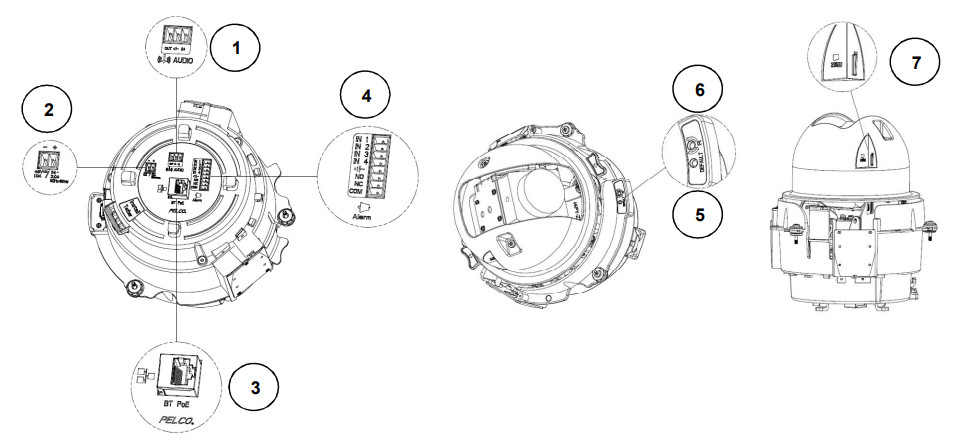
Figure 1. Connections
- Audio In/out: Via “IN” and “GND” ports, connect to an external device such as a microphone that receives sound for the camera. Via “OUT” and “GND” ports, connect to an external device to be triggered through alarm output signals.
- Power Terminal: The port is to connect with either external DC 48V or AC 24V power supply
- RJ-45 Network Port: Connect the RJ-45 connector to this port for network connection and also allow a PoE BT Class 5 (Environmental),PoE AT Class 4(Indoor) power sourcing equipment (PSE) to supply power through Ethernet cable.
- Alarm: Connect to an external device that can trigger alarm signals and device to be triggered by alarm output signals.
- Default Button: Press the button for 5 seconds to restore the camera’s settings back to the factory default.
- Reset Button: Press the button for approximately 1 second to reboot the camera.
- SD Card Slot: Insert a Micro SD card into the slot for local storage.
Installation
You can install the Spectra Professional 2 PTZ camera by using one of the following installations methods:
- Installation using pipe/conduit (not supplied). Refer to Pendant models on page 11
- Installation using a pendant mount (not supplied). Refer to Pendant models on page 12
- Installation in a suspended ceiling or fixed ceiling. Refer to In-Ceiling models on page 14
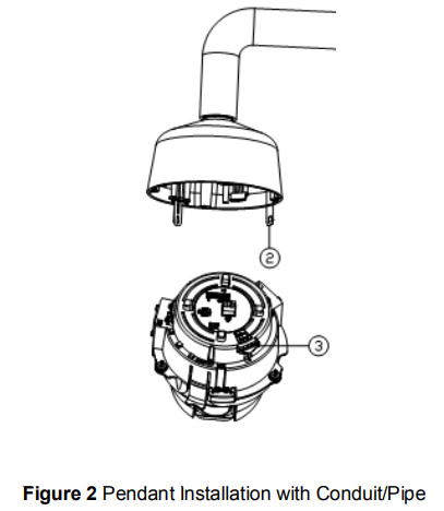
Pendant Installation with Conduit/Pipe
- Install Conduit (not supplied).
- Mount back box to the conduit. Where applicable, use weather-proof conduit.NOTE: Thread compound must be applied on environmental pendants. Not doing so might prevent the units from being separated in the future.
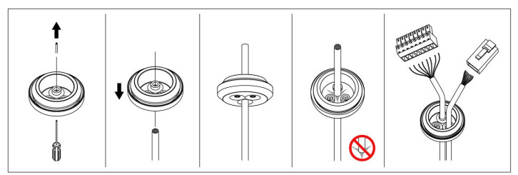
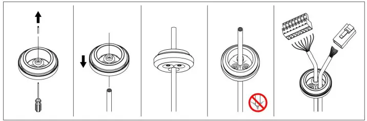
- Pull the wiring into the backbox. If using the supplied waterproof gland (recommended), puncture a round hole(s) in the gland that is smaller than the diameter of the cable that will be passed through the gland. Feed an unterminated cable thru the hole in the gland. Terminate the cable with the appropriate connector

- Install the camera.a. Align the tether from the backbox (Position #2) and attach it to the camera (Position #3) as shown. (There are red dots on the camera and the backbox to aid alignment.):b. Connect the power wiring and all the corresponding I/O connectors.c. Push the camera into the clips on both sides of the backbox until both sides click into place. The clips temporarily hold the camera in place.d. Screw in the three captive fasteners until they are secure.
- Install the lower domea. Attach the backbox tether to the lower dome from position #1 (backbox tether) to position #4 (lower dome) as shown.b. Align the backbox screws with the slots on the lower dome. There are red dots on the lower dome and the backbox to aid alignment.c. Push the lower dome onto the back box.d. Tighten the screws to secure the lower dome to the back box. Tightening torque: 7 ~ 9 lb/in or 8 ~ 10 kg/cm.
- Apply power to the dome. The dome system will complete a configuration sequence.
 b. Connect the power wiring and all the corresponding I/O connectors.c. Push the camera into the clips on both sides of the backbox until both sides click into place. The clips temporarily hold the camera in place.d. Screw in the three captive fasteners until they are secure.
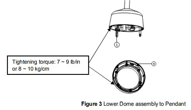 b. Align the backbox screws with the slots on the lower dome. There are red dots on the lower dome and the backbox to aid alignment.c. Push the lower dome onto the back box.d. Tighten the screws to secure the lower dome to the back box. Tightening torque: 7 ~ 9 lb/in or 8 ~ 10 kg/cm.
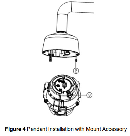
Pendant Installation with Mount Accessory
- Install the pendant mount (not supplied). Refer to the instructions supplied with the mount.
- Screw the compression connector onto the pendant backbox. Screw the lock nut onto the compression connector protruding from beneath the backbox. Tighten the lock nut until the compression connector is held firmly to the backbox.
- Pull the wiring into the backbox. If using the supplied waterproof gland (recommended), puncture a round hole(s) in the gland that is smaller than the diameter of the cable that will be passed through the gland. Feed an unterminated cable thru the hole in the gland. Terminate the cable with the appropriate connector
- Apply thread compound (supplied) to the threads on the backbox. Screw the backbox onto the pendant mount.NOTE: Thread compound must be applied to environmental pendants. Not doing so might prevent the units from being separated in the future.
- Connect the wiring.
- Install the camera:a. Align the tether from the backbox (Position #2) and attach it to the camera (Position #3) as shown (There are red dots on the camera and the backbox to aid alignment.):b. Connect the power wiring and all the corresponding I/O connectorsc. Push the camera into the clips on both sides until both sides click into place. The clips temporarily hold the camera in place.d. Screw in the three captive fasteners until they are secure.
- Install the lower dome.a. Attach the backbox tether to the lower dome from position #1 (backbox tether) to position #4 (lower dome) as shown:b. Align the backbox screws with the slots on the lower dome. There are red dots on the lower dome and the backbox to aid alignment.c. Push the lower dome onto the backbox.d. Tighten the screws to secure the lower dome to the backbox. Tightening torque: 7 ~ 9 lb/in or 8 ~ 10 kg/cm.
- Apply power to the dome. The dome system will complete a configuration sequence.
 b. Connect the power wiring and all the corresponding I/O connectorsc. Push the camera into the clips on both sides until both sides click into place. The clips temporarily hold the camera in place.d. Screw in the three captive fasteners until they are secure.
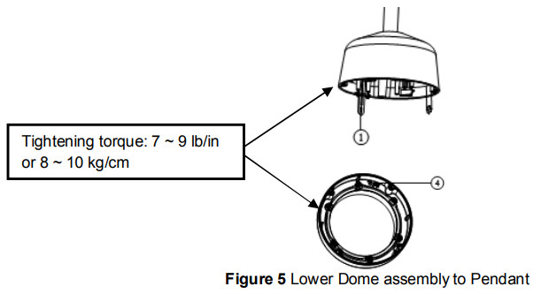 b. Align the backbox screws with the slots on the lower dome. There are red dots on the lower dome and the backbox to aid alignment.c. Push the lower dome onto the backbox.d. Tighten the screws to secure the lower dome to the backbox. Tightening torque: 7 ~ 9 lb/in or 8 ~ 10 kg/cm.
In-ceiling Installation
- Attach the guide pattern (supplied) to the mounting location.
- Cut out the circle according to the guide pattern.
- Attach a conduit fitting (not supplied) and locknut (not supplied)
- . Install a safety chain/cable (not supplied) to a ¼-20 threaded hole on the top of the backbox. The safety chain/cable should be capable of supporting up to 7.3 kg (16 pounds).
- Pull the wiring into the backbox through the conduit fitting.
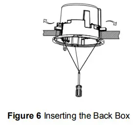
- Insert the backbox into the hole and fasten the 3 screws with a screwdriver so that the locking spring paddles can slide out to secure the back box into the ceiling (refer to Figure 5).
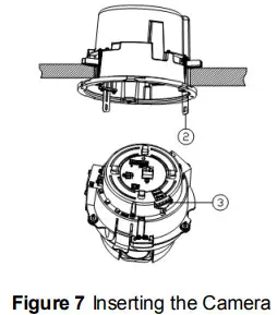
- Install the cameraa. Align the tether from the backbox (Position #2) and attach it to the camera (Position #3) as shown. (There are red dots on the backbox and camera to aid alignment.):b. Connect the power wiring and the corresponding I/O connectors c. Push the camera into the clips on both sides until both sides click into place. The clips temporarily hold the camera in place.d. Screw the three captive fasteners until they are secure.
- Install the lower domea. Attach the backbox tether to the lower dome from position #1 (backbox) to position #4 (lower dome) as shown:b. Push and rotate the lower dome clockwise onto the back box approximately 10 degrees to secure. (There are red dots on the lower dome and the backbox to aid alignment.).c. Tighten the lower dome to the backbox. Tightening torque: 7 ~ 9 lb/in or 8 ~ 10 kg/cm.
- Apply power to the dome. The dome system will complete a configuration sequence.
 b. Connect the power wiring and the corresponding I/O connectors c. Push the camera into the clips on both sides until both sides click into place. The clips temporarily hold the camera in place.d. Screw the three captive fasteners until they are secure.
Pelco Troubleshooting Contact Information
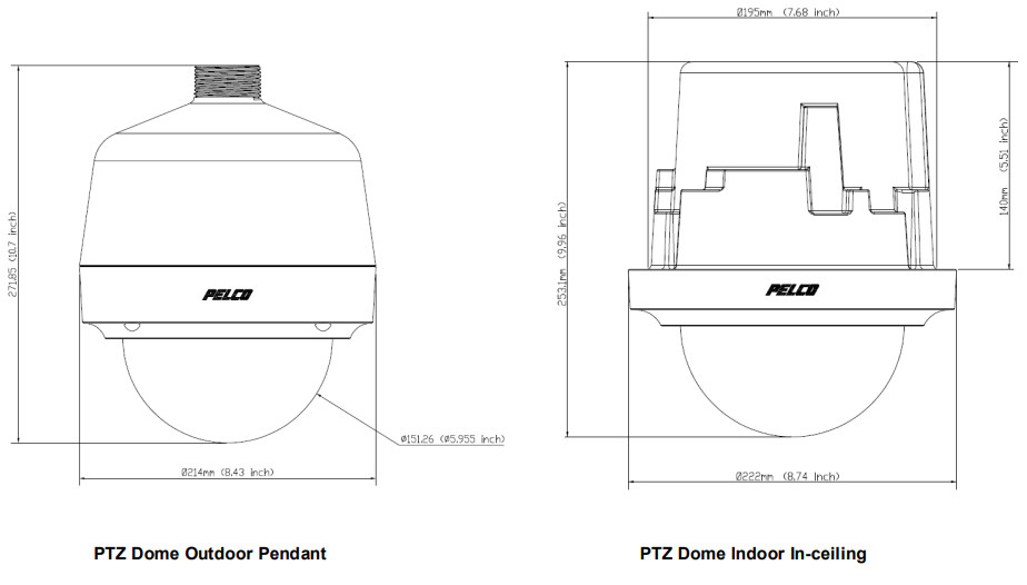
If the instructions provided fail to solve your problem, contact Pelco Product Support at 1-800-289-9100 (USA and Canada)+1-559-292-1981 (international) for assistance. Be sure to have the serial number available when calling.Do not try to repair the unit yourself. Leave maintenance and repairs to qualified technical personnel only.Note for Dimension DrawingsNOTE: VALUES IN PARENTHESES ARE INCHES; ALL OTHERS ARE CENTIMETERS.
Note for Dimension Drawings
![]() NOTE: VALUES IN PARENTHESES ARE INCHES; ALL OTHERS ARE CENTIMETERS.
NOTE: VALUES IN PARENTHESES ARE INCHES; ALL OTHERS ARE CENTIMETERS.
 This equipment contains electrical or electronic components that must be recycled properly to comply with Directive 2002/96/EC of the European Union -regarding the disposal of waste electrical and electronic equipment (WEEE). Contact your local dealer for procedures for recycling this equipment.
REVISION HISTORY
| Manual # | Date | Comments |
| C6675M | 21-Mar | Rev.01 |
Pelco, Inc.625 W. AlluvialFresno, California 93711United States USA & Canada Tel (800) 289-9100 Fax (800) 289-9150International Tel +1 (559) 292-1981 Fax+1 (559) 348-1120www.pelco.com
References
[xyz-ips snippet=”download-snippet”]