![]() Sarix® Value Series IR EnvironmentalBullet CamerasInstallation Manual
Sarix® Value Series IR EnvironmentalBullet CamerasInstallation Manual
Document number: C6673MPublication date: 05/21
Overview
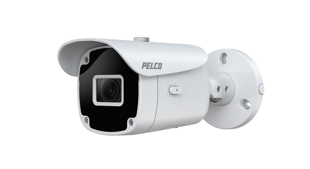
Sarix Value IBV Bullet Series cameras are ideal for covert surveillance that can help deter criminal activity. The Sarix Value Series features excellent image quality with great low light performance, color fidelity, and true wide dynamic range (WDR) for increased visibility in difficult lighting situations. And with built-in IR illumination, the camera can provide coverage even in total darkness. The varifocal lensing gives you the flexibility to set a range of fields of view.With IP66 rated ingress protection, the Sarix Value IBV Bullet Series can be deployed in a variety of indoor and environmental settings.
Package Contents
- IBV229-1ER / IBV529-1ER
- Screw pack and side lid
- Sunshield and screw
- Quick Installation Guide
- Waterproof cable gland
POE Requirements
- The camera is only to be connected to PoE networks without routing to outside plants.
- For PoE connection, use only UL listed I.T.E. with PoE output.
Use the camera only with a PoE source power supply that is UL listed, and limited power source (LPS) certified. The power supply should bear the UL listed and LPS marks. The power supply should also meet any safety and compliance requirements for the country of use.
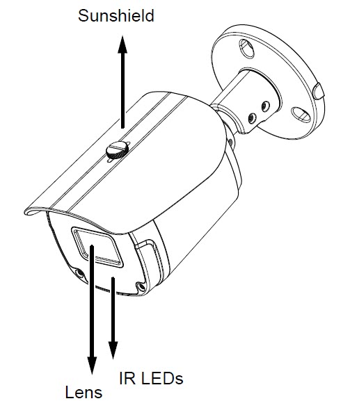
Physical Description
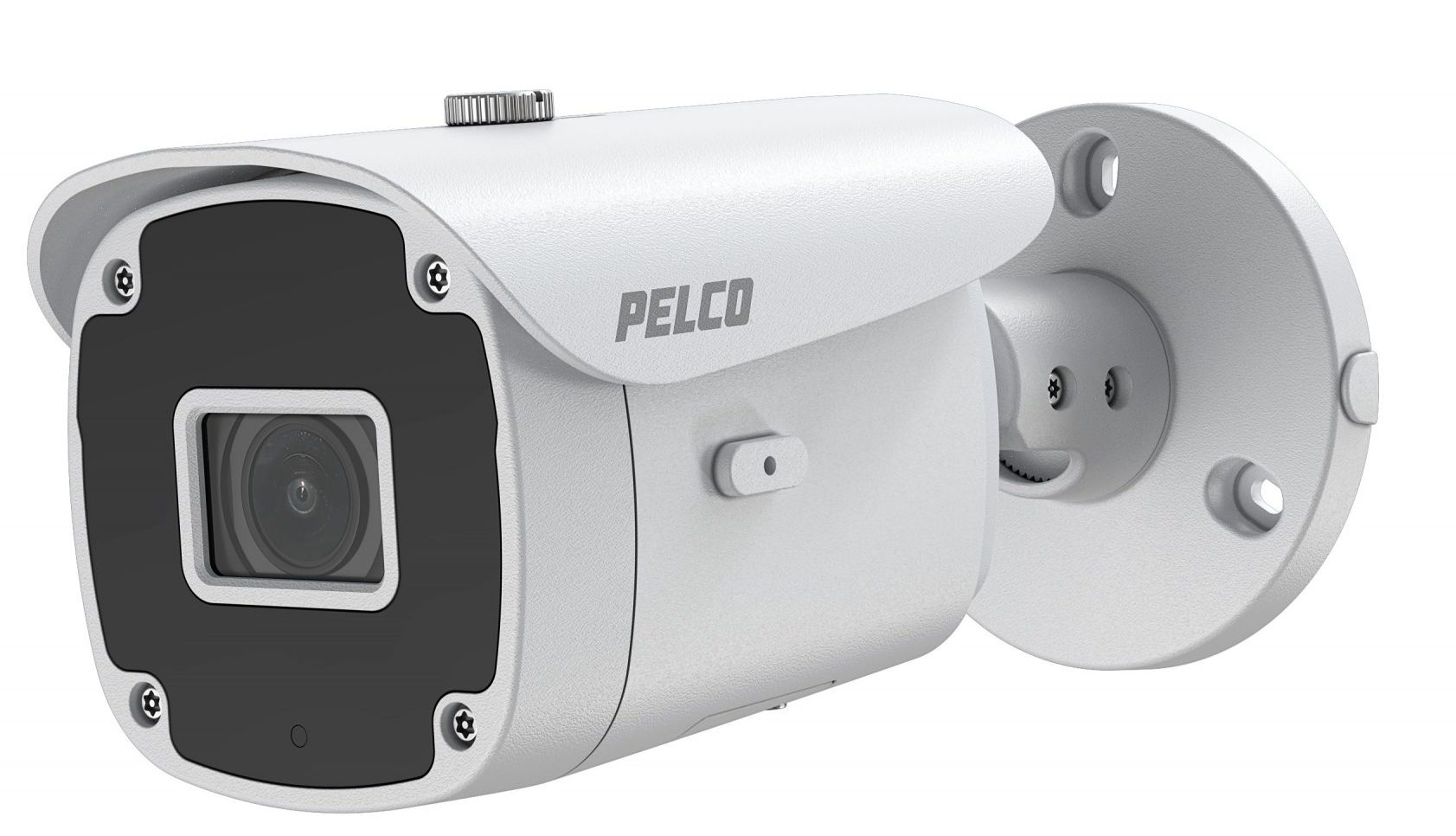
Outer View
Inner View

Installing the Hardware
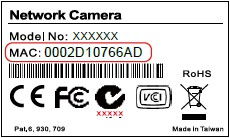
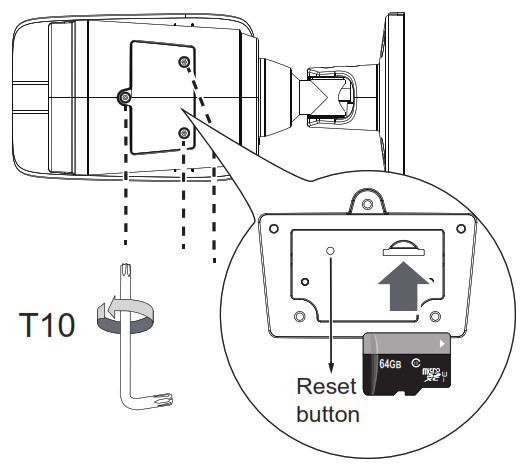
- Write down the MAC address of the camera for later use.

- Open the hatch at the bottom of the camera, and install a MicroSD card if onboard storage is desired.
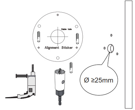
- Use the alignment sticker to drill mounting holes on the wall or ceiling. Drill a cabling routing hole if preferred.
- Route an Ethernet cable through the cabling hole.
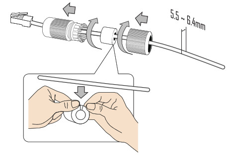
- Pass an Ethernet cable through the waterproof cable gland components, and through the rubber seal as shown below. Connect the Ethernet cable to the camera’s RJ45 connector.
- Install the seal ring and tighten the waterproof components.
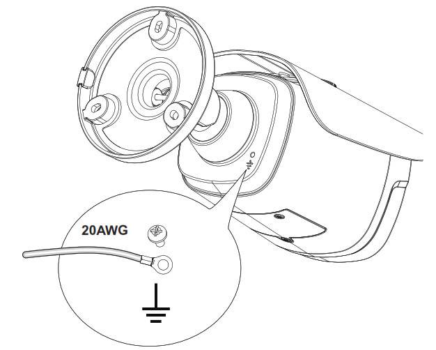
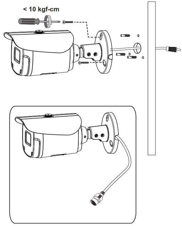
- Connect a ground wire to the grounding position at the back of the camera using the included screw.
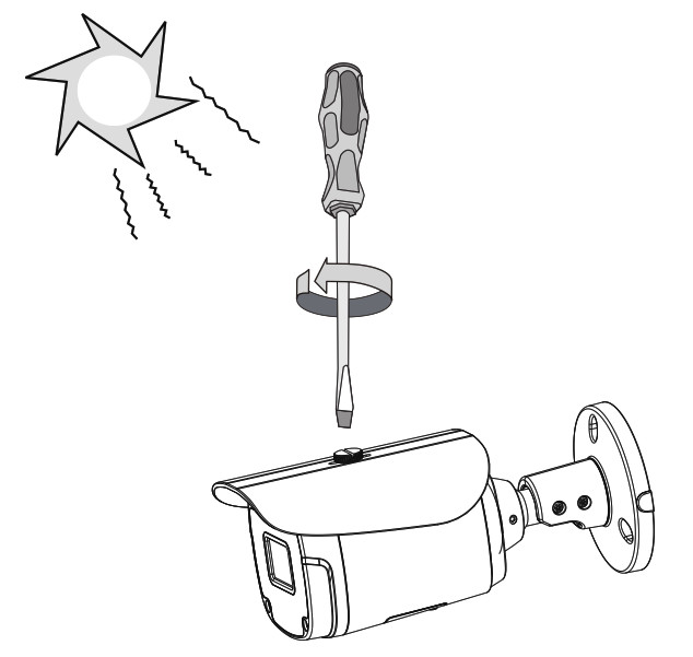
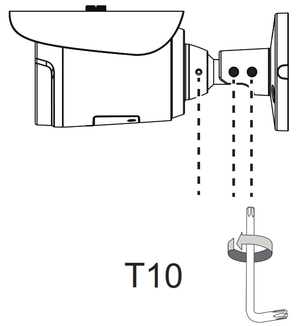
- Install the suns hield using a flat-blade screwdriver.
- Install the camera to the wall using the included screws. Note that if a routing hole through the wall is not possible, you can also route the cable through the side opening.


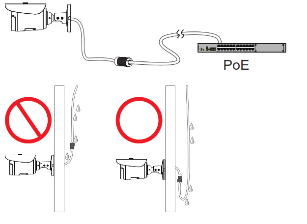
![]() Note: It is always a good practice to form a drip loop on cables. Moisture condensation or dripping water can eventually cause problems without the drip loop.
Note: It is always a good practice to form a drip loop on cables. Moisture condensation or dripping water can eventually cause problems without the drip loop.
Accessing the Camera
![]() Note: For security purposes, it is required that you create a user password when you access the camera for the first time.
Note: For security purposes, it is required that you create a user password when you access the camera for the first time.
- In its out-of-the-box configuration, the camera has a user name of “root” and no password assigned. In this state, the camera does not allow for video to stream or configurations to change. It is required that you set an administrative user password at this time. The creation of an administrative user password changes the state of the camera to its “operational mode,” where credentials must be provided in order to view live video or change its configuration.
- There is no provision for recovering a forgotten administrator user name or password. The camera can be restored to its out-of-the-box, no user name and password configuration by powering down, depressing the Factory Defaults button, and holding the button down for at least four seconds while powering the camera back up.
- If a user name and password exist, a Login page is presented when the camera is accessed.
The recommended browsers for your camera are the latest version of Microsoft™ Edge™, Google Chrome™ browser, or Mozilla® Firefox®. For supported browser versions, refer to the specification sheet.
- Discover the camera in VxToolbox.
- Use the IP address of the discovered camera and enter it into a web browser.Note: You can obtain your camera’s IP address or access the camera using VxToolbox software. If DHCP is enabled but a DHCP server is not on the network, the camera automatically assigns itself both an IPv4 link-local address (169.254.x.x, where the lower two octets are random) and a 192.168.0.20 address. Additional cameras will assign themselves different IPv4 link-local addresses and the next available 192.168.0xIP addresses in sequential order. For example, if three cameras are connected to a network without a DHCP server, the first camera to connect assigns itself the IP address 192.168.0.20, the second camera assigns itself 192.168.0.21, and the third camera assigns itself 192.168.0.22.
- Using one of the recommended browsers, you will be prompted to create an admin password. The first (admin) user is hardcoded as “root.” and cannot be changed.
- Commission the camera in VxToolbox and enter camera credentials.
Supplemental Resources
All Sarix Value Series supplemental resources (e.g. firmware, documentation, VxToolbox, and Device Utility) are available in one location: www.pelco.com/sarix-value.
Configuring the Password
The first time you log in to the camera, the firmware will prompt you for a password. Protecting your camera with a password can deter most cyber attacks.To configure the password:
- Type in a combination of alphabetic and numeric characters to fulfill the password strength requirement. The default name for the camera administrator is “root”, and can not be changed. Note Some, but not all, special ASCII characters are supported. Characters you can use in the password combination include: !, $, %, -, ., @, ^, _, and ~.
- Click Save.
- In the confirmation dialog box, type in the user name and password, and then click OK.
Adjusting Pan, Tilt, and Rotation
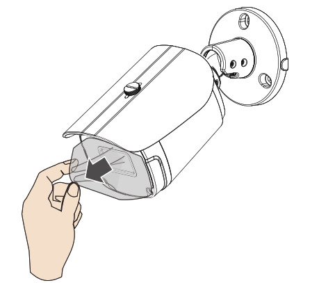
- Remove the protective sheet in front of the lens.
- Loosen the retention screws on the mount bracket.
- With a live view on your computer, rotate, pan, or tilt the camera until you acquire an optimal field of view.

Deploying the Camera on a Network
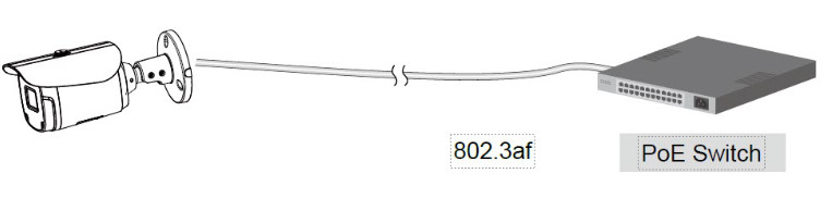
Using a PoE-enabled Switch
The Network Camera is PoE-compliant, allowing transmission of power and data via a single Ethernet cable. Follow the below illustration to connect the Network Camera to a PoE-enabled switch via Ethernet cable.
Using a Non-PoE Switch
 Using a Non-PoE Switch
Use a PoE power injector (optional) to connect between the Network Camera and a non-PoE switch.
Verifying the Installation
- Using a supported browser, navigate to the network camera.
- Verify that you can view live video from the camera.

Connecting to the Internet Via a Router
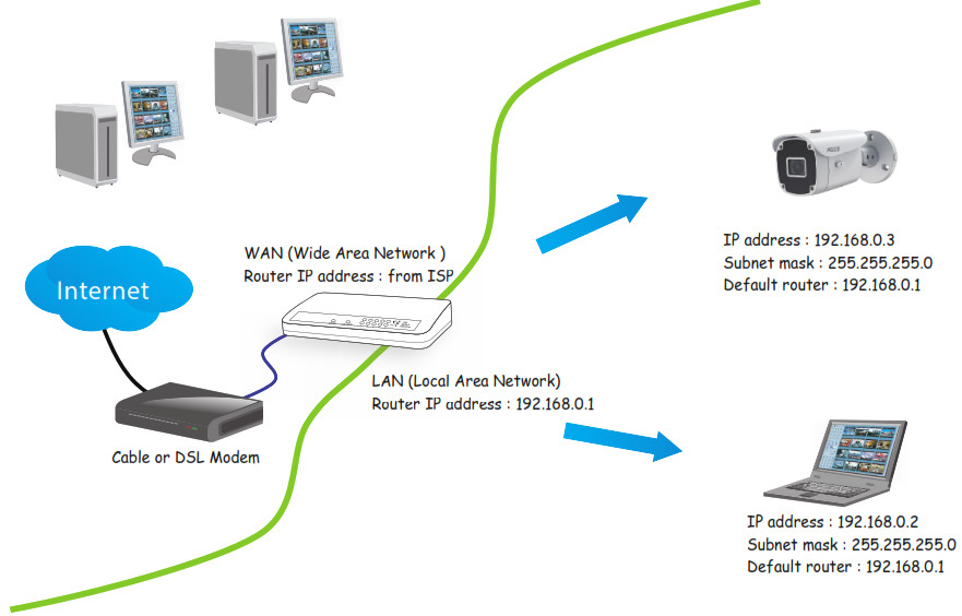
Before setting up the Network Camera over the Internet, make sure you have a router and connect it as described in this section.
- Connect your Network Camera behind a router, as shown below, using the correct IP addresses, subnet masks, and routers addresses for your installation. The IP addresses in the image are examples only.
- If the Local Area Network (LAN) IP address of your Network Camera is 192.168.0.3, forward the following ports for the Network Camera on the router.• HTTP port: default is 80• RTSP port: default is 554• RTP port for video: default is 5556• RTCP port for video: default is 5557
- If you have changed the port numbers on the Network page, open the ports accordingly on your router. For information on how to forward ports on the router, please refer to your router’s user manual.
- Find out the public IP address of your router provided by your ISP (Internet Service Provider). Use the public IP and the secondary HTTP port to access the Network Camera from the Internet. See the current Sarix Value Series Operations Manual, the section titled Configuring the Network General Settings.
- If you are required to do so, connect to the internet using a static IP for the Network Camera.
- If you are connected to the Internet via a DSL line, connect to the internet using PPPoE (Point-to-point over Ethernet).
- Configure the router, virtual server, or firewall so that the router can forward any data coming into a preconfigured port number to a network camera on the private network, and allow data from the camera to be transmitted to the outside of the network over the same path. If, for example, the router and IP settings are as presented in this table:
Device IP address: internal port IP address: external port(mapped port on the router) Public IP of the router 122.146.57.120 N/A LAN IP of the router 192.168.2.1 N/A Camera 1 192.168.2.10:80 122.146.57.120:8000 Camera 2 192.168.2.11:80 122.146.57.120:8001 Then:• Camera 1 data is forwarded from 122.146.57.120:8000 to 192.168.2.10:80.• Camera 2 data is forwarded from 122.146.57.120:8001 to 192.168.2.11:80.• Access a camera behind the router using the HTTP request http://122.146.57.120:8000.
- If you change the port numbers on the Network configuration page, open the ports accordingly on your router.For example, you can open a management session with your router to configure access through the router to the camera within your local network. Contact your network administrator for router configuration, if you need to troubleshoot. For more information with network configuration options (such as that of streaming ports), see the current Sarix Value Series Operations Manual, the section titled Configuring the Network Settings.
Troubleshooting
Performing a Hardware Reset
The reset button is used to reset the system or restore the factory default settings. Sometimes resetting the system can return the camera to normal operation. If system problems remain after performing a hardware reset, restore the camera to the factory settings and configure it again.
- To perform a Hardware Reset, press the recessed reset button, and then wait for the Network Camera to reboot.
- To Restore a camera to the factory settings, press and hold the reset button until the status LED rapidly blinks. When the settings are restored, the status LED will blink green and red during normal operation.
![]() Caution: All settings will be restored to the factory default settings when you press and hold the reset button.
Caution: All settings will be restored to the factory default settings when you press and hold the reset button.
Pelco Troubleshooting Contact Information
For further assistance, contact Pelco Product Support at 1-800-289-9100 (the USA and Canada) or +1-559292-1981 (international).Do not try to repair the unit yourself. Leave maintenance and repairs to qualified technical personnel only.
![]()
![]()
Pelco, Inc.625 W. Alluvial Ave., Fresno, California 93711 United States(800) 289-9100 Tel(800) 289-9150 Fax+1 (559) 292-1981 International Tel+1 (559) 348-1120 International Faxwww.pelco.comPelco, the Pelco logo, and other trademarks associated with Pelco products referred to in this publication are trademarks of Pelco, Inc.or its affiliates. ONVIF and the ONVIF logo are trademarks of ONVIF Inc. All other product names and services are the property of their respective companies. Product specifications and availability are subject to change without notice.© Copyright 2021, Pelco, Inc. All rights reserved.
References
[xyz-ips snippet=”download-snippet”]