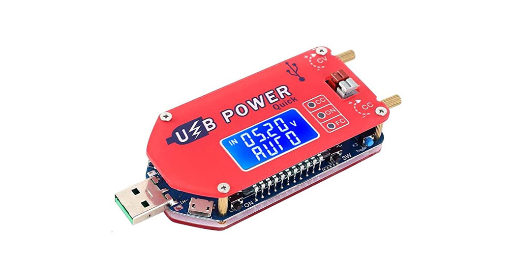
PEMENOL 15W DC-DC LCD USBPower Supply ModuleUser Manual
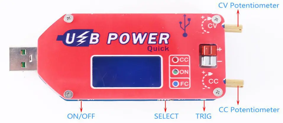
- CV Potentiometer: Adjust output voltage. Increase the output voltage when rotating clockwise. Please rotate CV potentiometer 10 turns in counterclockwise if the output voltage cannot be adjusted.
- CC Potentiometer: Adjust output current. Increase the output current when rotating clockwise. Notelt is not keeping a fixed output current. When the load current reaches the set current value, the module starts to fix output this current value. Short circuit output terminal when adjust output current.
- ON LED: Green Output indicator. It will turn ON when there is a output at output terminal. Otherwise it is OFF.
- CC LED: Red Constant current output indicator. It enters the constant current state when the load current reaches the set current and CC constant current indicator turns ON.
- FC LED: Blue Fast charge deceiving indicator. Fast charge protocol after the successful deception.
Brief Intro:
ZK-DP3A is a 15W DC adjustable constant voltage/constant current step up/down power supply module with LED digital tube display. It supports fast charging for QC2.0, QC3.0, AFC, FCP, SCP fast charge protocol. Displaying output voltage, output current and output power. Adjustable output voltage and current. Setting output current to meet the require. It can be used as ordinary buck power supply module, charger, and LED constant current driver. Simple and efficient, practical.
Highlights:
- Support fast charger
- Support anti-backflow protection
- Support adjustable constant voltage constant
- LCD HD display
- Four input power modes
- Support over-current protection
- Support over-voltage protection
- Support over power protection
- Support over-temperature protection
- Support over current protection
- Support charging mode
- High resolution
- Multiple parameters are displayed simultaneously
- Comfortable outer casing
- Display Input voltage, Output voltage/current/power/capacity statistics.
Parameters:
| 1 | Input Voltage for Pads | DC 4.0V-13.0V |
| 2 | Input Voltage for USB | DC 5.0V |
| 3 | Output Voltage | DC 1V-30.0V |
| 4 | Output Current | 2A |
| 5 | Output Power | 15W(Max) |
| 6 | Current Display Range | 0~2.2A |
| 7 | Working current | 30mA |
| 8 | Short Circuit Protection | √ |
| 9 | Anti-backflow Protection | √ |
| 10 | Over-Voltage Protection | √ |
| 11 | Over-Power Protection | √ |
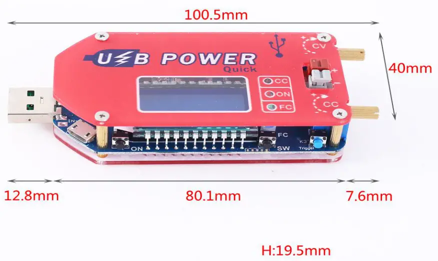
| 12 | Size | 100.5*40*19.5mm |
*Long press means keep press for more than 3sceond.
- ON/OFF Button: Short press is used to turn ON or OFF output voltage at display mode, or trigger charge deception function at fast charge protocol selection mode;Long press is used to set default ON or OFF for next re-power at display mode.
- SW Button: Short press to switch display output voltage and output current; or trigger charge deception function at fast charge protocol selection mode. Long press is used to switch display output current, output power and capacity statistics.
- TRIG Button: Short press to select fast charging protocol. Long press to enter or exit the fast charge protocol selection interface.
- CV Potentiometer: Adjust output voltage, increase the output voltage when rotating clockwise. Please rotate the CV potentiometer 10 turns in counterclockwise if the output voltage cannot be adjusted.
- CC Potentiometer: Adjust output current, Increase the output current when rotating clockwise. Note:It is not keeping a fixed output current; When the load current reaches the set current value, the module starts to fix output the current value. Short circuit output terminal when adjust output current.
ON LED: Green Output indicator. It will turn ON when there is a output at output terminal, Otherwise it is OFF.CC LED: Red Constant current output indicator. It enters the constant current state when the load current reaches the set current and CC constant current indicator turns ON.FC LED: Blue Fast charge deceiving indicator. It will turn ON when Fast charge protocol function is successful.
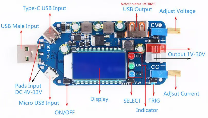
Input and output
Input terminal: Four input methods:
- Standard Type A USB Male. It just can input DC 5V.
- Micro USB Female.It just can input DC 5V.
- Type-C USB Female.It just can input DC 5V.
- Pads input DC 4.0V-13.0V.*It can only choose one input method.
2 output terminals:
- USB female connector
- Quick-connect terminal
*Note that the two are directly connected and the voltage is always the same. It can output DC 1.0V-30.0V.
Fast Charge Deception Function:
![]() Support intelligent fast charge deception function to solve the problem of insufficient power supply of USB input port.
Support intelligent fast charge deception function to solve the problem of insufficient power supply of USB input port.![]() Support mainstream fast charging protocol: QC2.0, QC3.0, AFC, FCP, SCP.
Support mainstream fast charging protocol: QC2.0, QC3.0, AFC, FCP, SCP.![]() User can choose not to deception or automatically choose the deception mode.
User can choose not to deception or automatically choose the deception mode.![]() Keep pressing button TRIG for 2 seconds, entering into fast charging protocol selection interface, Screen will display fast charging protocol.
Keep pressing button TRIG for 2 seconds, entering into fast charging protocol selection interface, Screen will display fast charging protocol.![]() Short press button TRIG to select fast charging protocol.
Short press button TRIG to select fast charging protocol.![]() Short press button ON/OFF or SELECT to trigger fast charging protocol. It will display OK and FC indicator turn ON if the triggering is successful, Otherwise display Err and FC indicator turn OFF.
Short press button ON/OFF or SELECT to trigger fast charging protocol. It will display OK and FC indicator turn ON if the triggering is successful, Otherwise display Err and FC indicator turn OFF.![]() Keep pressing button TRIG for 2 seconds again to save and exit setting mode. Module will remember this selection.
Keep pressing button TRIG for 2 seconds again to save and exit setting mode. Module will remember this selection.![]() User can select the AUTO mode and the module automatically selects the deception protocol if user don’t know which protocol the charger supported.
User can select the AUTO mode and the module automatically selects the deception protocol if user don’t know which protocol the charger supported.![]() Users can choose the OFF mode if user has no need for fast charge deception function.
Users can choose the OFF mode if user has no need for fast charge deception function.
Muti-Protective function:
- Over-Voltage Protection: Module will turn OFF output voltage automatically if output voltage is more then 30.5V.
- Over-Current Protection: Module will turn OFF output automatically if output current is more then 2A.
- Over-Power Protection: Module will turn OFF output automatically if output power is more then 15W. It will display ‘OPP’. User need reduce load power and then press ‘ON/OFF’ button.
- Current error: Large display error when output current is less than 0.05A. It can not display output current if current is 10~40mA.
- Over Temperature Protection: Module will turn OFF output automatically if temperature is more then 100℃. It will display ‘OTP’. User need reduce load power and then press ‘ON/OFF’ button.
How to use it? Please note!!!!1. As an ordinary step down power module:
- Connect right input voltage at input terminal;
- Adjust CV constant voltage potentiometer to set output voltage according to your needs.
- Rotate CV potentiometer counterclockwise more than 10 turns if the output voltage can not be adjusted.
- Rotate CC potentiometer counterclockwise more than 10 turns at first.
- Short circuit between OUT+ and OUT-(Connect both by wire). Or test Output short circuit current by multimeter at 10A or 20A (Connect two Test Probes to output terminal on module). Or Short circuit output terminal directly.
- Rotate CC constant current potentiometer clockwise to set output current according to require over-current protection value.
- Test and using.E.g: Module’s maximum output current is 1A if display 1A on multimeter. Red LED indicator will turn on if output reach to 1A. Otherwise LED is OFF.
- The output voltage will decrease due to the current sampling resistor at the output. The higher the current, the more the voltage is reduced.
- Output current can not keep fixed value output. It changes with load. But It can not exceed setting output current value.
2. As a charger:
*Power supply module can not be used as charger module if it does not support constant current function. The voltage difference between the battery with insufficient voltage and the charger is very large, which will cause excessive charging current even damage the battery. So it need to keep charging in constant current mode to reachinga certain level, and then automatically switch back to constant voltage charging.
*Make sure floating charge voltage and charge current for battery. If the lithium battery’s parameter is 3.7V/2200mAh, then the float charge voltage is 4.2V, and the maximum charging current is 1C, which is 2200mA.
- Connect right input voltage at input terminal. (Note: Please don’t connect load during setting parameter).
- Short circuit between OUT+ and OUT-(Connect both by wire), Or test output voltage by multimeter and adjust CV potentiometer to make sure output voltage reach to required floating charge voltage. (If charge a 3.7V lithium battery, adjust the output voltage to 4.2V). Or Short circuit output terminal directly.
- Rotate CC potentiometer counterclockwise more than 10 turns at first.
- Test Output short circuit current by multimeter at 10A or 20A (Connect two Test Probes to output terminal on module)
- Rotate CC constant current potentiometer clockwise to set output current according to required charge current value.
- Connect battery at output terminal and start to charging.
 report this ad
3. As a high power LED constant current driver:
- Make sure LED working current and maximum working voltage.
- Connect right input voltage at input terminal. (Note:Please don’t connect load during setting parameter).
- Short circuit between OUT+ and OUT-(Connect both by wire). Or test output voltage by multimeter at output terminal and adjust CV potentiometer to set output voltage to LED’s maximum working voltage.
- Rotate CC potentiometer counterclockwise more than 10 turns.
- Test Output short circuit current by multimeter at 10A or 20A(Connect two Test Probes to output terminal on module)Or Short circuit output terminal directly.
- Rotate CC constant current potentiometer clockwise to set output current according to require LED working current.
- Connect LED and test.
Warm tips:
- It is a DC power module, So it can not connect to AC power.
- Please don’t short output.
- Please make sure input power is more than load power.
- Please step down output power if module is hot.
- Rotate CV potentiometer counterclockwise more than 10 turns if the output voltage can not be adjusted.
- Output current can not keep fix value output.It changes with load.But It can not exceed set output current value.
- There is a protective film on the surface of the shell. It is recommended to tear it off for a clearer effect.
- Please read user manual and description before use.
Application:
- Ordinary power supply
- Battery charger
- LED drive power
- Instrument voltage display
- Test meter
- Circuit test
- Power conversion
- Fan governor
Package:
- 1pcs ZK-DP3A USB CVCC Buck Boost Voltage Converter
After-Sales:
*We have always been keen to provide customers with the best quality service at the most competitive price.*Looking forward to get progress and growth with all of you.*For more product questions and inquiries, please send your advice to [email protected]*Thank you for your purchase!
References
[xyz-ips snippet=”download-snippet”]