
![]()
Medium Full Motion Mount Instruction ManualV3.0
Model: PSMFK12

Web Site: www.perlesmith.com
Thank you for choosing this Perlesmith product! At Perlesmith we strive to provide you with the best quality products and services in the industry.Please share your experience of our product with others on www.perlesmith.com/pages/reviews if you are satisfied. Should you have any issues, please don’t hesitate to contact us.Technical Support:1-800-556-6806 Mon-Fri 10am – 5pm (PST) (USA) (CAN)Other Info:[email protected] (US/CA/DE/UK/FR/IT/ES/AU)
IMPORTANT SAFETY INFORMATION
Please carefully read all instructions before attempting installation. If you do not understand the instructions or have any concerns or questions, please contact our Technical Support line at 1-800-556-6806 or customer service at [email protected]CAUTION: Avoid potential personal injuries and property damage!
- Do not use this product for any purpose that is not explicitly specified in this manual. Do not exceed weight capacity. We are not liable for damage or injury caused by improper mounting, incorrect assembly or inappropriate use.
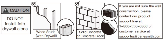
- This product is designed for use in wood stud, solid concrete, and concrete block walls– DO NOT install into drywall alone.
- The wall must be capable of supporting five times the weight of the TV and mount combined.
Check the VESA Pattern of Your TV before the Installation
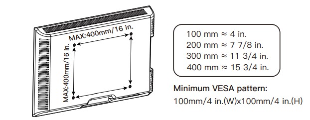
If your TV VESA is greater than 400×400 mm/16×16 in. or less than VESA 100x100mm/4x4in., this mount is NOT compatible.
If this mount is NOT compatible, please contact customer service at [email protected] to find a compatible mount.
Verify Your Wall Construction
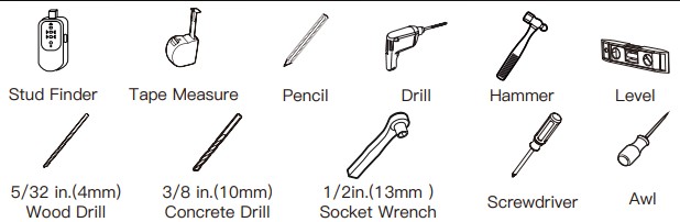
Tools Needed (Not included)
Supplied Parts and Hardware
![]() Warning:This product contains small items that could be a choking hazard if swallowed.Before starting assembly, verify all parts are included and undamaged. Do not use damaged or defective parts. lf you require replacement parts, contact our Product Support line at 1-800-556-6806 or customer service at [email protected]
Warning:This product contains small items that could be a choking hazard if swallowed.Before starting assembly, verify all parts are included and undamaged. Do not use damaged or defective parts. lf you require replacement parts, contact our Product Support line at 1-800-556-6806 or customer service at [email protected]
- Please note: Not all hardware included in this package will be used.
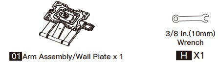
Supplied Parts and Hardware for Step 1
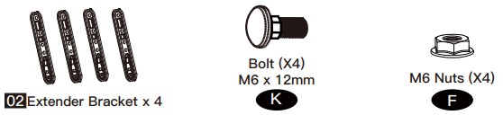
Supplied Parts and Hardware for Step 2(Optional)
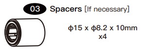
 Supplied Parts and Hardware for Step 3
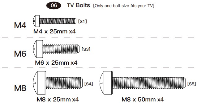
Note: The bolts are shown in accordance with the actual size
Supplied Parts and Hardware for Step 4
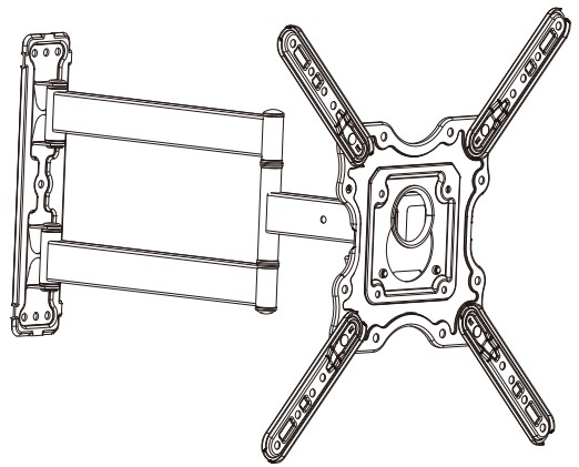
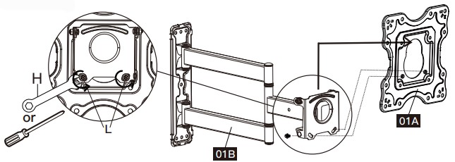
Step 1 Detach Faceplate
Remove the preassembled bolts [L] using the wrench [H] or screwdriver (not included) to separate the faceplate [01A] from the arm assembly/wall plate [01B]. Keep bolts [L] for use in Step 5.
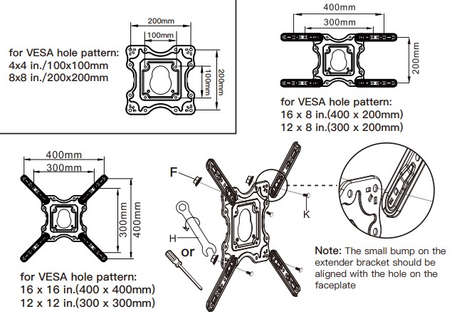
Step 2 Choose the Combination that Applies to Your VESA Hole Pattern
| Option ANo Need to Attach Extender Brackets [02] to Faceplate | Option BNeed to Attach Extender Brackets [02] to Faceplate |
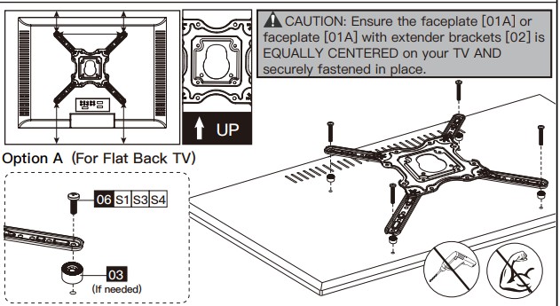
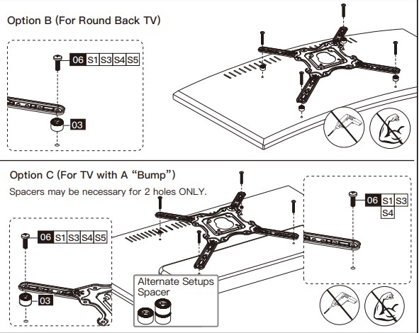
Step 3Secure the Faceplate [01A] or Faceplate [01A] with Extender Brackets [02] to TV
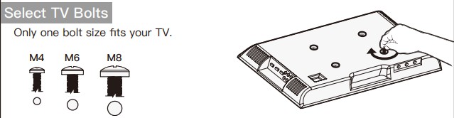
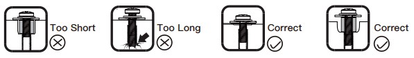
Bolt length: Verify adequate thread engagement with bolts or bolts/spacers combination. We recommend thread engagement by at least 5 turns.-Too short will not hold the TV.-Too long will damage the TV.
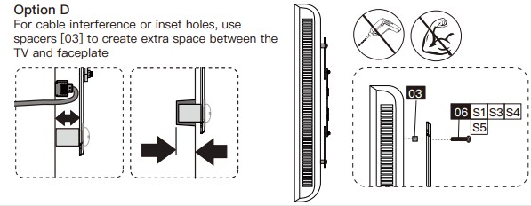
Note: If necessary, the spacers can be used in multi-layer. If the installation fails after trying various methods, please contact customer service at [email protected].
Step 4Attach the Arm Assembly/Wall Plate [01B] to WallFor wood stud installation, follow STEP 4AFor concrete installation, follow STEP 4B
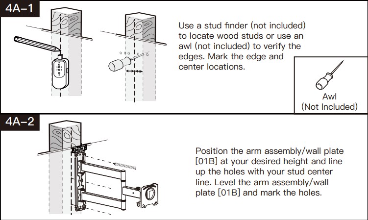
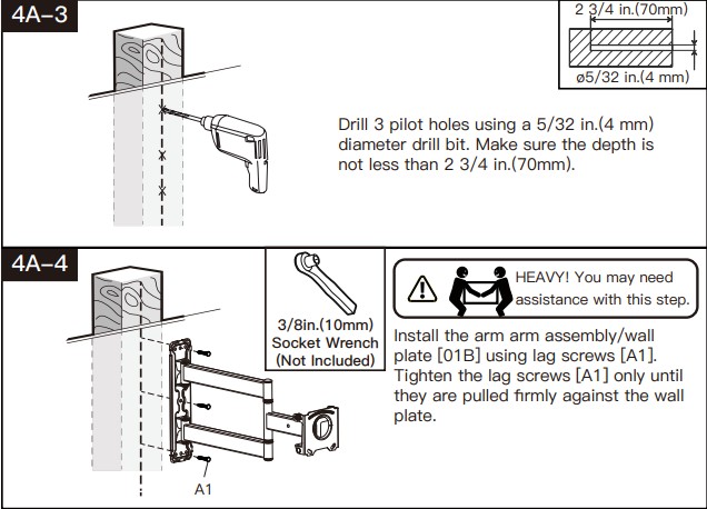
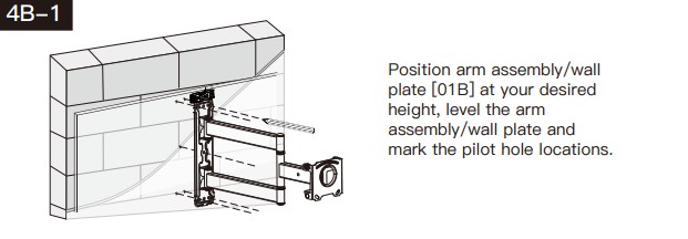
Step 4A Wood Stud Option
![]() WARNING:
WARNING:
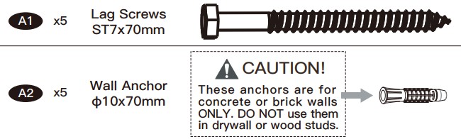
- Avoid potential personal injury or property damage! DO NOT over-tighten the lag screws [A1]. Tighten the lag screws [A1] only until they are pulled firmly against the arm assembly/wall plate [01B].
- DO NOT USE ANCHOR [A2] FOR THIS STEP!
- Ensure the arm assembly/wall plate [01B] is securely fastened to the wall before continuing on to the next step.
- Any material covering the wall must not exceed 5/8 in. (16 mm)
- Nominal wood stud size: common 2 x 4 in. (51 x 102 mm) minimum 1½ x 3½ in. (38 x 89 mm)
- Stud center must be verified

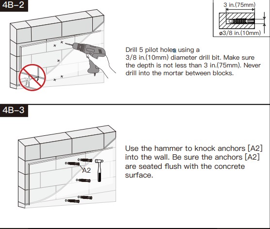
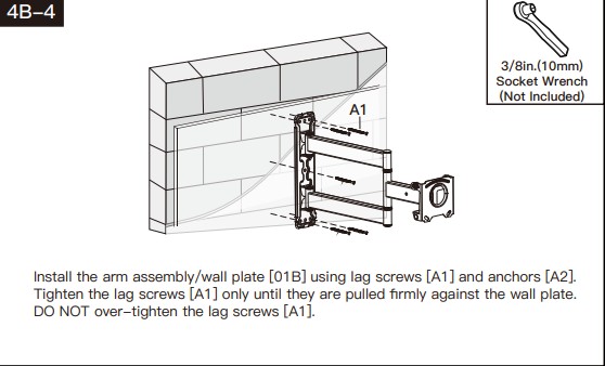
Step 4BSolid Concrete or Concrete Block Option
![]() WARNING:
WARNING:
- Avoid potential personal injury or property damage! DO NOT over-tighten the lag screws [A1]. Tighten the lag screws [A1] only until they are pulled firmly against the arm assembly/wall plate [01B].
- Ensure the arm assembly/wall plate [01B] is securely fastened to the wall before continuing on to the next step.
- Any material covering the wall must not exceed 5/8 in. (16 mm)
- Mount the arm assembly/wall plate directly onto the concrete surface
- Minimum solid concrete thickness: 203 mm (8 in.)
- Minimum concrete block size: 203 x 203 x 406 mm (8 x 8 x 16 in.)

Step 5Secure TV to Arm Assembly/Wall Plate [01B]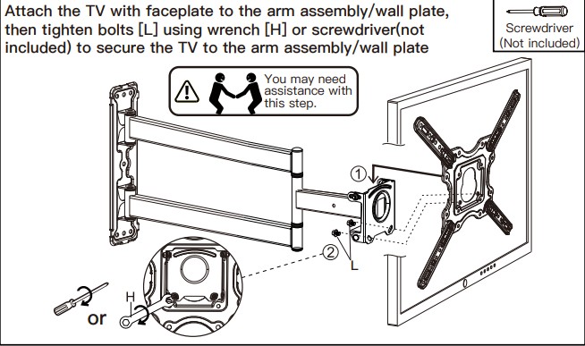
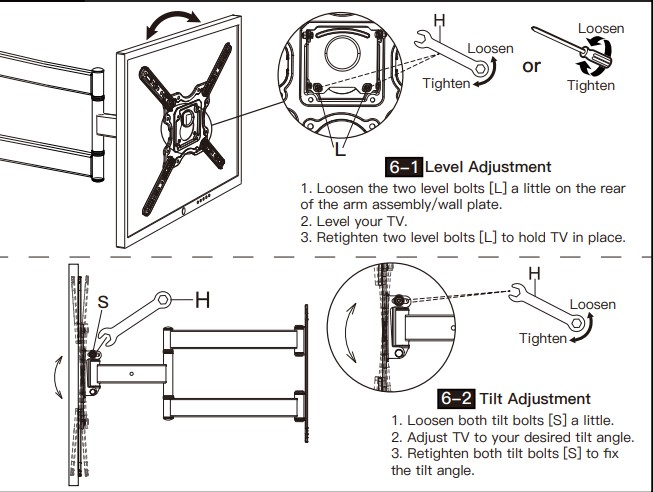
Step 6Adjustments
Thank you again for choosingthis Perlesmith product!
All of us at Perlesmith do appreciate your product purchase. We hope that you are as happy with your product as we are designing and manufacturing it for you. We strive to provide you with the best quality products and services in the industry.Please share your experience of our product with others at www.perlesmith.com/pages/reviews if you are satisfied. Should you have any issues, please don’t hesitate to contact us.Technical Support: 1-800-556-6806 Mon-Fri 10am – 5pm (PST) (USA) (CAN)Other Info: [email protected] (US/CA/DE/UK/FR/IT/ES/AU)Please check www.perlesmith.com for more products and company information.
References
[xyz-ips snippet=”download-snippet”]