![]() TV Stand Instruction ManualV1.0
TV Stand Instruction ManualV1.0
 Model: PSTVS21
 https://www.perlesmith.com
Thank you for choosing this PERLESMITH product! At PERLESMITH we strive to provide you with the best quality products and services in the industry. Please share yourexperience of our product with others at www.perlesmith.com/pages/reviews if you are satisfied.Should you have any issues, please don’t hesitate to contact us.Technical Support:1-800-556-6806 Mon-Fri 10am – 5pm (PST) (USA) (CAN)Other Info:[email protected] (US)[email protected] (CA)
IMPORTANT SAFETY INSTRUCTIONS
Please carefully read all instructions before attempting installation. If you do not understand the instructions or have any concerns or questions, please contact our Technical Support line at 1-800-556-6806 or customer service at [email protected] (US)/[email protected] (CA)CAUTION: Avoid potential personal injuries and property damage!Do not use this product for any purpose that is not explicitly specified in this manual. Do not exceed weight capacity. We are not liable for damage or injury caused by improper mounting, incorrect assembly, or inappropriate use.
Check the VESA Pattern of TV Before the Installation
If your TV VESA is greater than 600×400 mm/24×16 in. or lessthan VESA 100x100mm/4x4in., this TV stand is NOT compatible.If this TV stand is NOT compatible, please contact customer service at [email protected] (US)/[email protected] (CA) to find a compatible product.
Tools Needed [Not Included]
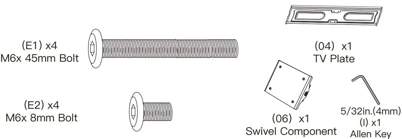
Supplied Parts and Hardware
![]() WARNING: This product contains small items that could be a choking hazard if swallowed.Before starting assembly, verify all parts are included and undamaged. Do not use damaged or defective parts. lf you require replacement parts, contact our Product Support line at1-800-556-6806 or customer service at [email protected] (US)/s[email protected] (CA)• Please note:Not all hardware included in this package will be used.
WARNING: This product contains small items that could be a choking hazard if swallowed.Before starting assembly, verify all parts are included and undamaged. Do not use damaged or defective parts. lf you require replacement parts, contact our Product Support line at1-800-556-6806 or customer service at [email protected] (US)/s[email protected] (CA)• Please note:Not all hardware included in this package will be used.
Supplied Parts and Hardware for Step 1
Supplied Parts and Hardware for Step 2
Note: The bolt is shown in accordance with the actual size.
Supplied Parts and Hardware for Step 3
Supplied Parts and Hardware for Step 4
Note: The bolts and spacers are shown in accordance with the actual size
Supplied Parts and Hardware for Step 5
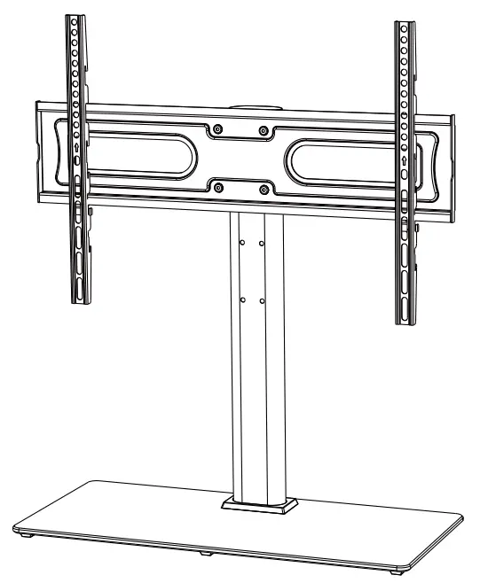
Step 1 Assemble the Base
Step 1-1Place foot pads [F] to the painted side of the tempered glass base [01] in the cornersNote: Kindly note that the tempered glass base is designed to show the shiny glass side facing up
Step 1-2Connect the support pillar [02] to the tempered glass base [01]Attach the tempered glass base by using bolts [B], steel washers [D], and plastic washers [C].
Step 2 Connect the TV Plate [04] to Support Pillar [02]
Note: There are three choices for height adjustment. You can choose your desired height position while connecting the swivel component [06] and TV plate [04] to support the pillar [02].
Note: Make sure the bump of the TV plate faces the back side of the TV stand.You may need assistance with this step
Step 4 Secure the TV Brackets [05] to TV
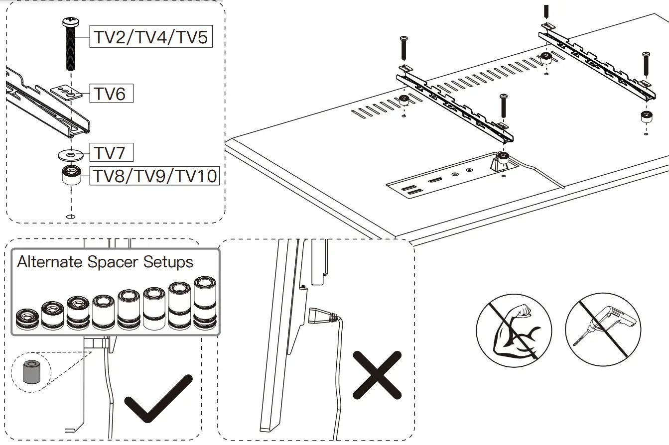
Select TV BoltsOnly one bolt size fits your TV.
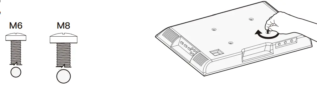
Bolt length: Verify adequate thread engagement with bolts or bolts/spacers combination. We recommend thread engagement by at least 5 turns.
- Too short will not hold the TV.
- Too long will damage the TV.
Note: If necessary, the spacers can be used in multi-layer. If the installation fails after trying various methods, please contact customer service at [email protected] (US)/[email protected] (CA).
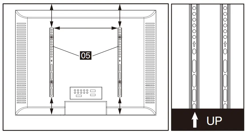
![]() CAUTION: Ensure the TV brackets [05] are EQUALLY CENTERED on your TV and securely fastened in place.PLEASE NOTE: The bolt hole locations on your TV may vary in accordance with the manufacturer’s design of the TV. We are only illustrating the possible locations of the bolt holes.Option A (For Flat Back TV)
CAUTION: Ensure the TV brackets [05] are EQUALLY CENTERED on your TV and securely fastened in place.PLEASE NOTE: The bolt hole locations on your TV may vary in accordance with the manufacturer’s design of the TV. We are only illustrating the possible locations of the bolt holes.Option A (For Flat Back TV)
Option B (For Flat Back TV)The spacers must be used with washers (TV7) to stop spacers from falling down.
Option C (For Round Back TV)The spacers must be used with washers (TV7) to stop spacers from falling down.
Option D (For TV with A “Bump”)Spacers may be necessary for 2 holes ONLY.The spacers must be used with washers (TV7) to stop spacers from falling down.
Option EFor cable interference or inset holes, use spacers [TV8], [TV9], and [TV10] to create extra space between the TV and TV bracketsAlternate Spacer SetupsThe spacers must be used with washers (TV7) to stop spacers from falling down.
Step 5 Attach TV to the TV Plate [04] and Manage the Wires
TV brackets are three-height-adjustable.You can choose the proper height.
|
|
Insert the safety locks [G] into the upward-facing hooks at the midway to lower part of the TV bracket.Then tighten the bolts of the safety locks [G] until the bolts touch the TV plate.
Step 6 Adjust Swivel Angle of TV Stand
If necessary,the TV plate or TV can be swiveled manually.
report this ad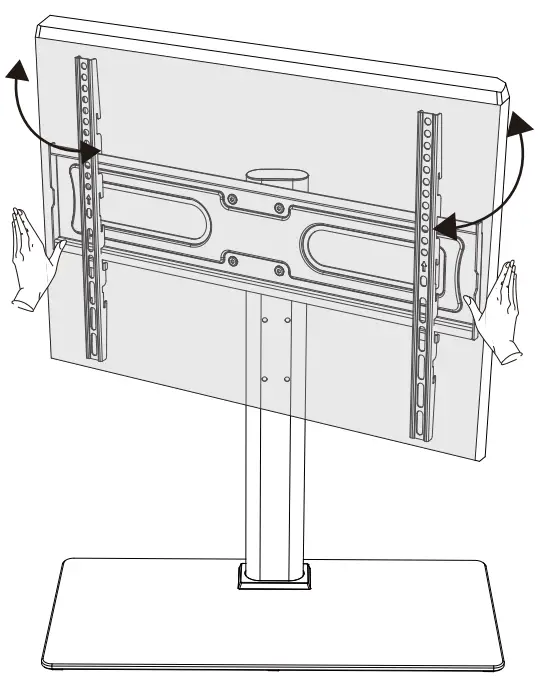
References
[xyz-ips snippet=”download-snippet”]