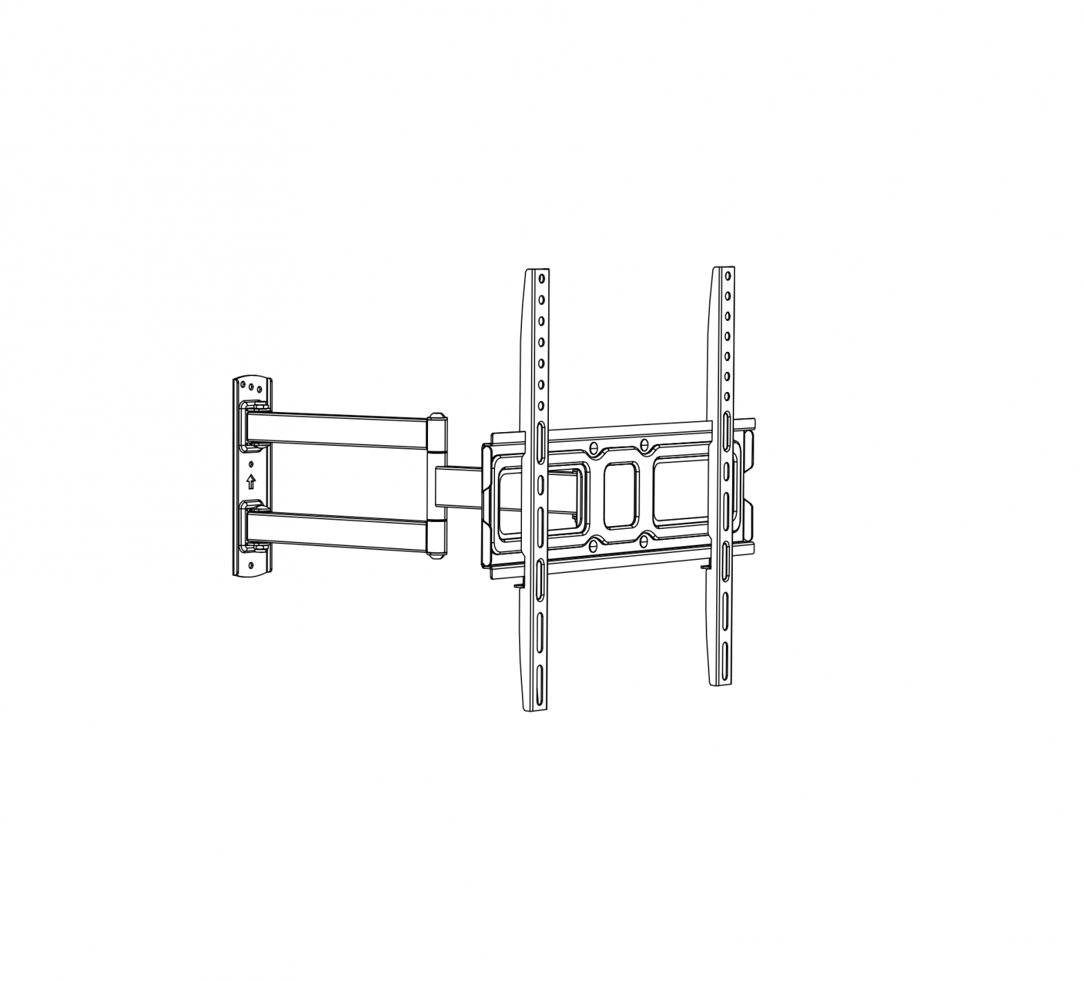
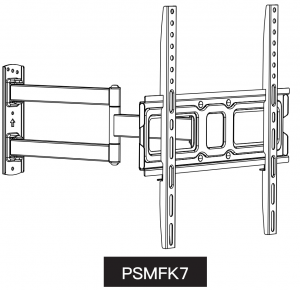
PERLESMITH TV Wall Mount Bracket Full Motion Single Articulating Arm
WARNING!
WARNING! SEVERE PERSONAL INJURY AND PROPERTY DAMAGE CAN RESULT FROM IMPROPER INSTALLATION OR ASSEMBLY. READ FOLLOWING WARNINGS BEFOREBEGINNING.
- If you do not understand the instructions or have any concerns or questions, please contact customer service at support[email protected]
- Do not install or assemble if the parts or hardware is damaged or missing. Not all parts and hardware included will be used. If you require replacement parts, contact customer service at [email protected]
- This product may contain moving parts. Use with caution.
- DO NOT INSTALL INTO DRYWALL ALONE.
- Please check www.perlesmith.com for more products and company information.
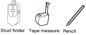
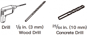
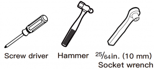
Tools Needed (Not Included)
   |
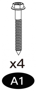
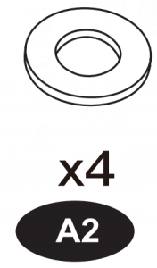
Supplied Hardware
| Hardware (Wall /Product) | ||
|
Lag Bolts M6X60
|
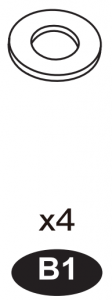
Washers Ø6mm
|
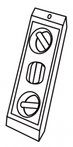
Level
|
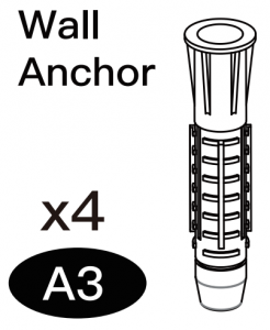 |
These anchors are for concrete or brick walls ONLY. DO NOT use them in drywall or wood studs. |
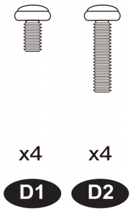
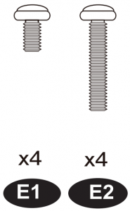
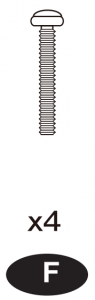
| TV Screws / Washers | |||||
|
WashersØ6mmM4-5-6
|
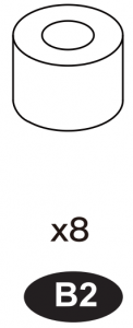
SpacersL10mm
|
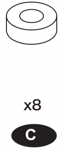
Spacers L5mm
|
Philips ScrewsM6 x 15mmM6 x 30mm
|
Philips ScrewsM8 x 15mmM8 x 45mm
|
Philips ScrewsM4 x 30mm
|
STEP 1
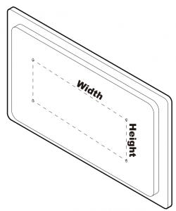 Measure the distance between the holes located at the back of your TV (these measures may form the shape of a square, or a rectangle) and check that these taken measures are within the VESA(*) range for this wall mount. (*) VESA: International standard established by the TV manufacturers used to determine if LCD / LED TVs are compatible with wall mounts. Measure the distance between the holes located at the back of your TV (these measures may form the shape of a square, or a rectangle) and check that these taken measures are within the VESA(*) range for this wall mount. (*) VESA: International standard established by the TV manufacturers used to determine if LCD / LED TVs are compatible with wall mounts. |
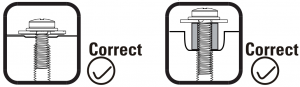
| Check TV screws
Hand thread screws into the threaded inserts on the back of your TV to determine which screw diameter (M4, M6, or M8) to use. |
  |
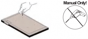
STEP 2
| For Flat screen TV
|
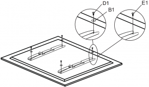
For Curved TV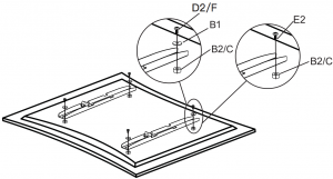 |
STEP 3A For Wood Stud Installation

|
| 3A-1
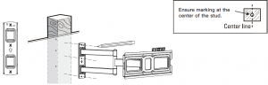
Use a stud finder (not included) to locate wood stud Mark the edge and center locations |
| 3A-2
|
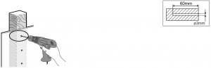
| 3A-3
Drill 3 pilot holes using a Vs in.(3mm) diameter drill bit. Make sure the depth is not less than 2.36 in. (60mm). |
| 3A-4
|

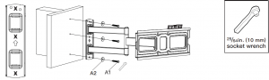 Mount the wall plate using 3 sets of M6 lag bolts A1 and washers A2 with a socket wrench (not included).
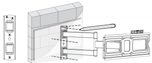
STEP 3B For Concrete Wall Installation
|
| 3B-1
Position the wall plate at your desired height, level the wall plate and mark the pilot hole locations. |
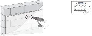
| 3B-2
Drill 4 pilot holes using a 25/64 in. (10mm) diameter drill bit. Make sure the depth is not less than 2.56 in.(65mm). |
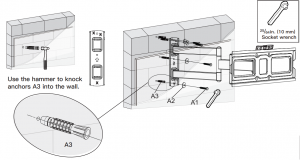
| 3B-3
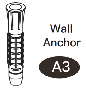
Install wall plate using lag bolts A1, washers A2 and anchors A3. Tighten the lag bolts until they are pulled firmly against the wall plate. |
STEP 4 Hang the TV onto the wall plate
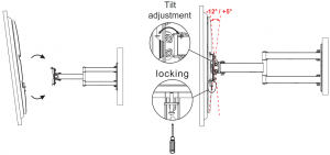 |
Step 5 Level Adjustment
If needed, the TV can be leveled +/-3 degrees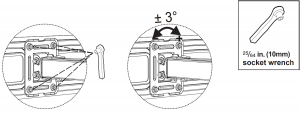 |

References
[xyz-ips snippet=”download-snippet”]