![]()
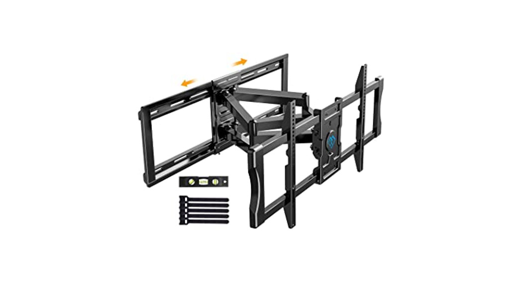
TV Wall MountInstruction Manual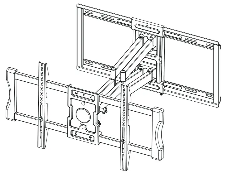
Model:PSLF6V2.0
Thank you for choosing this Perlesmith product! At Perlesmith we strive to provide you with the best quality products and services in the industry. Please share your experience of our product with others at www.perlesmith.com/pages/reviews if you are satisfied. Should you have any issues, please don’t hesitate to contact us.
Website: www.perlesmith.com
Technical Support:1-800-556-6806 Mon-Fri 10am – 5pm (PST) (USA) (CAN)Other Info:[email protected] (US)[email protected] (CA)
IMPORTANT SAFETY INFORMATION
Please carefully read all instructions before attempting installation. If you do not understand the instructions or have any concerns or questions, please contact our Technical Support line at 1-800-556-6806 or customer service at [email protected] (US)/[email protected] (CA)CAUTION: Avoid potential personal injuries and property damage!
- Do not use this product for any purpose that is not explicitly specified in this manual. Do not exceed weight capacity. We are not liable for damage or injury caused by improper mounting, incorrect assembly, or inappropriate use.
- This product is designed for use in wood stud, solid concrete, concrete block brick walls – DO NOT install into drywall alone.
- The wall must be capable of supporting five times the weight of the TV and mount combined.
Weight Restrictions
![]()
If your TV weighs more, this mount is NOT compatible.
![]() WARNINGDO NOT exceed the maximum weight indicated. This mounting system is intended for use only within the maximum weights indicated. Use with products heavier than the maximum weights indicated may result in failure of the mount and its accessories, causing possible damage and or injury.
WARNINGDO NOT exceed the maximum weight indicated. This mounting system is intended for use only within the maximum weights indicated. Use with products heavier than the maximum weights indicated may result in failure of the mount and its accessories, causing possible damage and or injury.
Check the VESA Pattern of Your TV before the Installation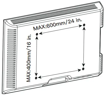
Minimum VESA pattern: 200mm/8 in.(W)x100mm/4 in.(H)
| 100 mm ≈ 4 in.200 mm ≈ 7 7/8 in.400 mm ≈ 15 3/4 in.300 mm ≈ 11 3/4 in.600 mm ≈ 23 6/10 in. |
If your TV VESA is greater than 600×400 mm/24×16 in. or less than VESA 200x100mm/8x4in., this mount is NOT compatible.
Verify Your Wall Construction
![]() CAUTIONDO NOT install into drywall alone
CAUTIONDO NOT install into drywall alone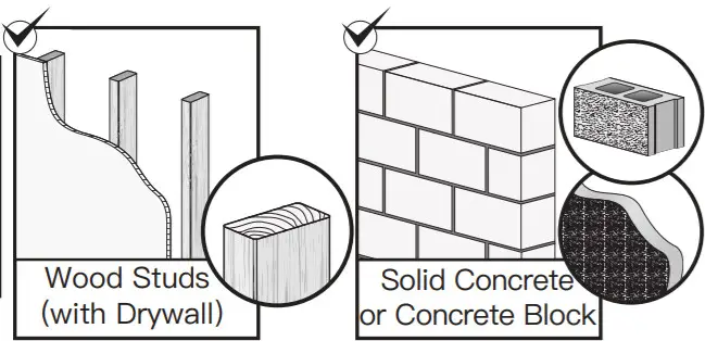
If you are not sure about the wall construction, please contact our product support line at 1-800-556-6806 or customer service at [email protected] (US)[email protected] (CA)
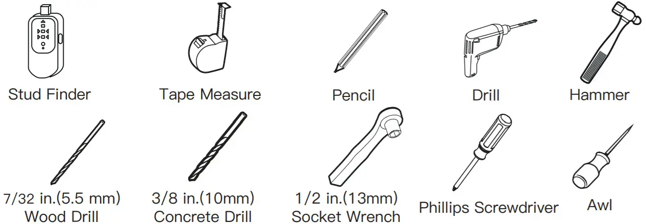
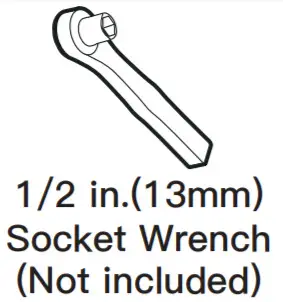
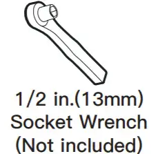
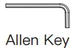
Tools Needed (Not included)
Supplied Parts and Hardware
![]() Warning: This product contains small items that could be a choking hazard if swallowed.Before starting assembly, verify all parts are included and undamaged. Do not use damaged or defective parts. if you require replacement parts, contact our Product Support line at 1-800-556-6806 or customer service at [email protected] (US)/[email protected] (CA)
Warning: This product contains small items that could be a choking hazard if swallowed.Before starting assembly, verify all parts are included and undamaged. Do not use damaged or defective parts. if you require replacement parts, contact our Product Support line at 1-800-556-6806 or customer service at [email protected] (US)/[email protected] (CA)
- Please note: Not all hardware included in this package will be used.
Supplied Parts and Hardware for Step 1The TV brackets are attached to the arm assembly/ wall plate with plastic cable ties
 TV Bracket
03 x2
 |
 |
07 TV Bolts [Only one bolt size fits your TV]Note: The bolts are shown in accordance with the actual size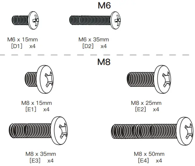
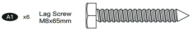
Supplied Parts and Hardware for Step 2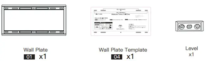
Note: The lag screw is shown in accordance with the actual size
 |
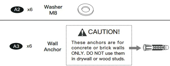 |
Supplied Parts and Hardware for Step 3 to Step 6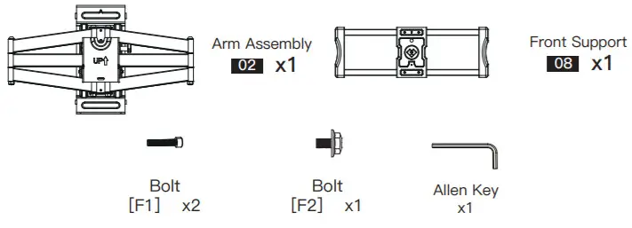
Step 1 Secure the TV Brackets to TV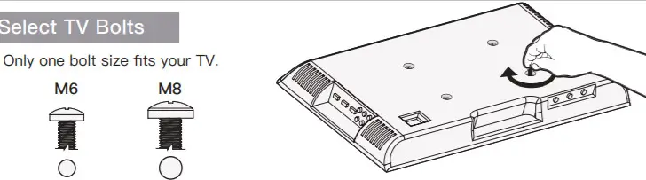
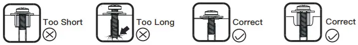
Bolt length: Verify adequate thread engagement with bolts or bolts/spacers combination.We recommend thread engagement by at least 5 turns.-Too short will not hold the TV.-Too long will damage the TV.
Note: If necessary, the spacers can be used in multi-layer. If the installation fails after trying various methods, please contact customer service at[email protected] (US)/[email protected] (CA)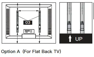
![]() CAUTION: Ensure the TV brackets [03] are EQUALLY CENTERED on your TV AND securely fastened in place.
CAUTION: Ensure the TV brackets [03] are EQUALLY CENTERED on your TV AND securely fastened in place.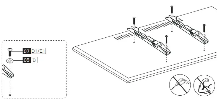
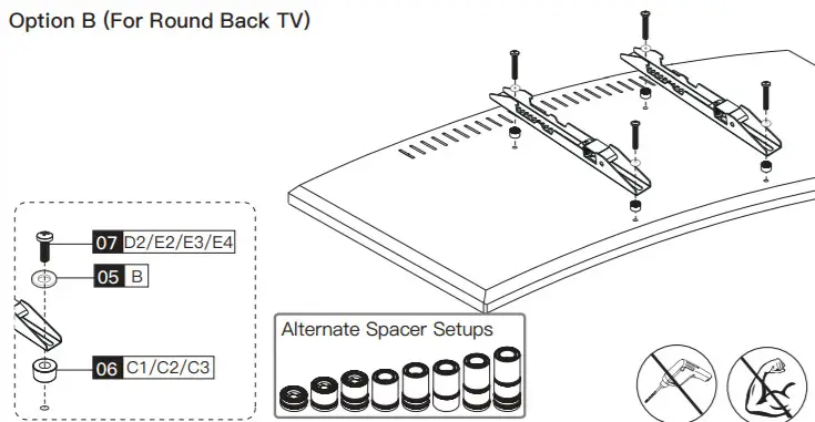
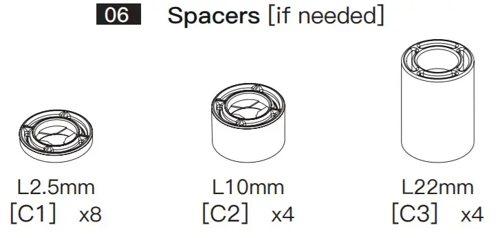
Option C (For TV with A “Bump”) Spacers may be necessary for 2 holes ONLY.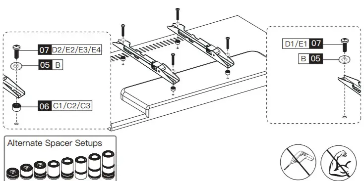
Option DFor cable interference or inset holes, use spacers [06] to create extra space between the TV and TV brackets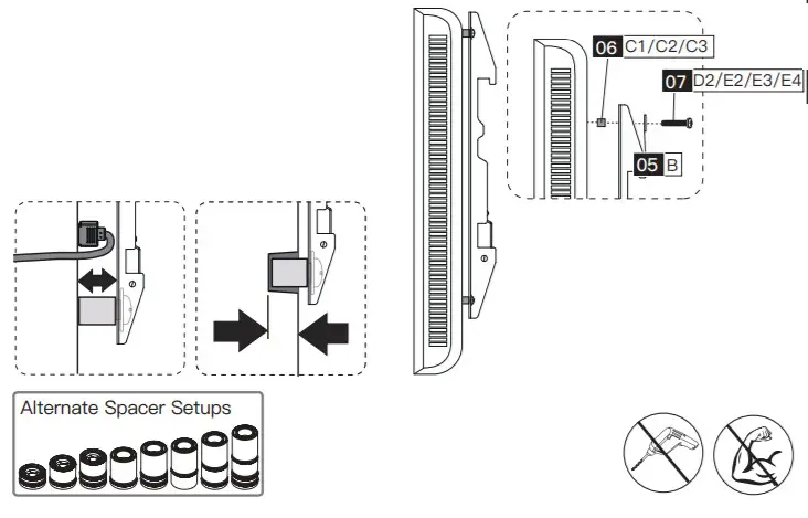
Step 2 Attach the Wall Plate [01] to WallFor wood stud installation, follow STEP 2AFor concrete installation, follow STEP 2BStep 2A Wood Stud Option
![]() WARNING:
WARNING:
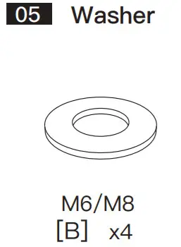
- Avoid potential personal injury or property damage! DO NOT over-tighten the lag screws [A1]. Tighten the lag screws [A1] only until the washers [A2] is pulled firmly against the wall plate.
- DONOT USE ANCHOR [A3] FOR THIS STEP!
- Ensure the wall plate [01] is securely fastened to the wall before continuing to the next step.
- Any material covering the wall must not exceed 5/8 in. (16 mm)
- Nominal wood stud size: common 2 x 4 in. (51 x 102 mm) minimum 1½ x 3½ in. (38 x 89 mm)
- Stud center must be verified

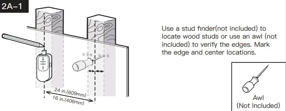
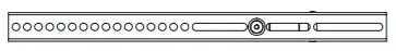
Position the wall plate template [04] at your desired height and line up the holes with your stud centerline. Level the wall plate template [04] and mark the holes.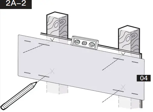
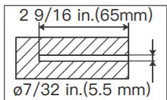
Drill 4 pilot holes using a 7/32 in.(5.5 mm) diameter drill bit. Make sure the depth is not less than 2 9/16 in.(65mm).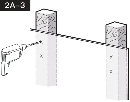
Install the wall plate using lag screws [A1] and washer [A2]. Tighten the lag screws [A1] only until the washers [A2] are pulled firmly against the wallplate.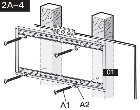
![]() You may need assistance with this step.
You may need assistance with this step.
Step 2B Solid Concrete or Concrete Block Option
WARNING:
- Avoid potential personal injury or property damage! DO NOT over-tighten the lag screws [A1]. Tighten the lag screws [A1] only until the washers [A2] are pulled firmly against the wall plate.
- Ensure the wall plate [01] is securely fastened to the wall before continuing to the next step.
- Any material covering the wall must not exceed 5/8 in. (16 mm)
- Mount the wall plate directly onto the concrete surface
- Minimum solid concrete thickness: 203 mm (8 in.)
- Minimum concrete block size: 203 x 203 x 406 mm (8 x 8 x 16 in.)
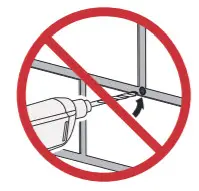
- Never drill into the mortar between blocks
Position the wall plate template [04] at your desired height, level the wall plate template, and mark the pilot hole locations.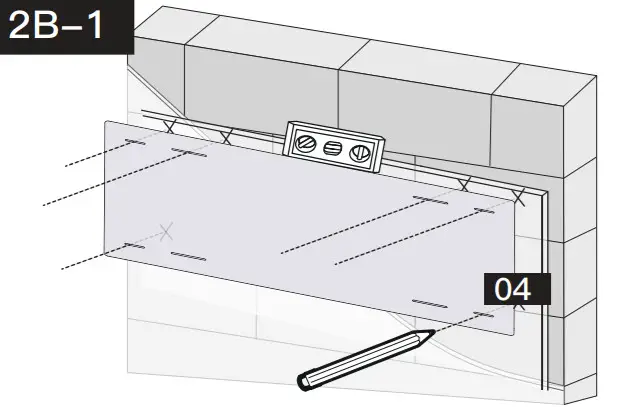
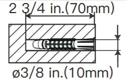
Drill 6 pilot holes using a 3/8 in.(10mm)diameter drill bit. Make sure the depth is not less than 2 3/4 in.(70mm). Never drill into the mortar between blocks.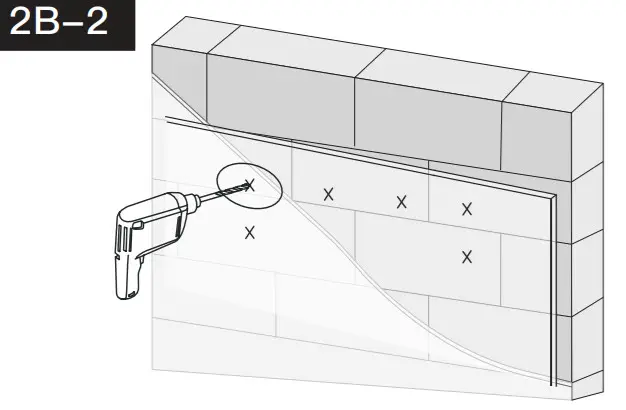
 |
 |
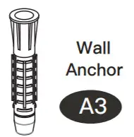
Use the hammer to knock anchors [A3] into the wall. Be sure the anchors [A3] are seated flush with the concrete surface.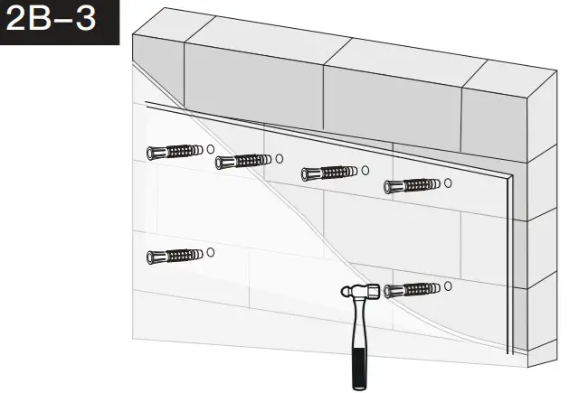
Install wall plate using lag screws [A1], washers [A2], and anchors [A3]. Tighten the lag screws [A1] only until the washers [A2] is pulled firmly against the wall plate. DO NOT over-tighten the lag screws [A1].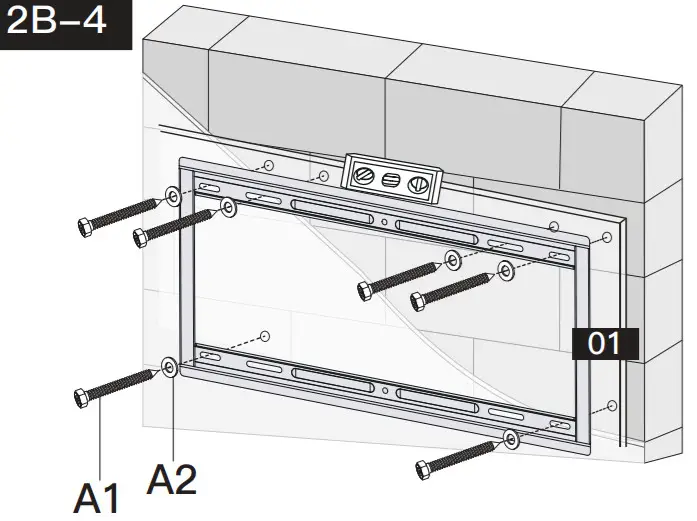
![]() You may need assistance with this step.
You may need assistance with this step.
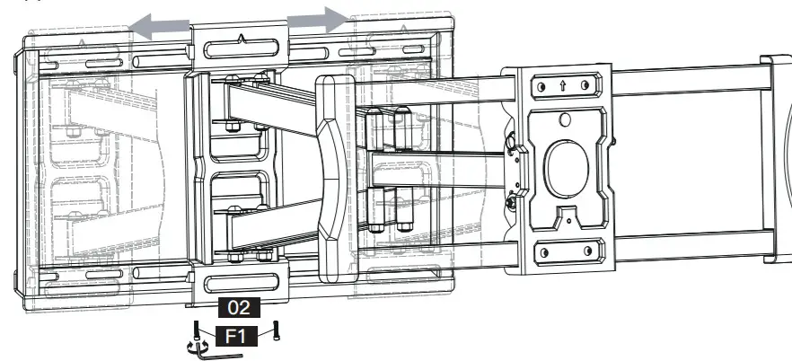
Step 3 Secure the Arm Assembly [02] to Wall Plate [01]
- Hang the arm assembly [02] to the wall plate [01].
- Shift the arm assembly [02] along with the wall plate [01] to your desired position.
- Secure the arm assembly [02] to the wall plate [01] using bolts [F1].
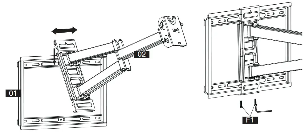
![]() Note: The bolts [F1] need to be tightened hard.
Note: The bolts [F1] need to be tightened hard.
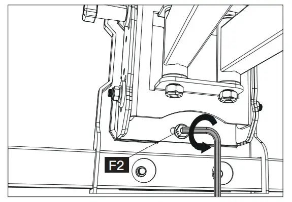
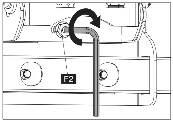
Step 4 Secure Front Support to Arm Assembly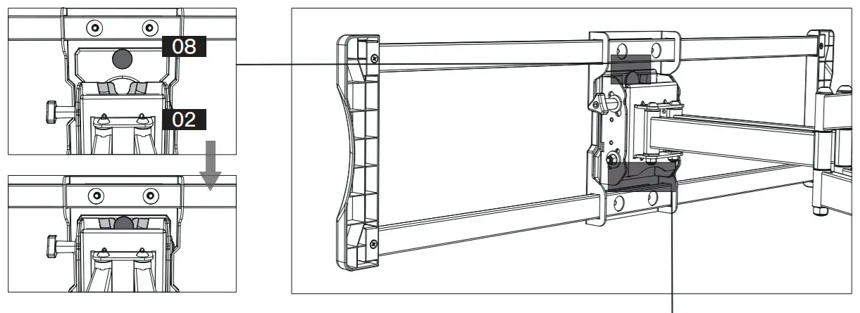
- Make sure the big button in Front Support [08] hangs on the hook of the arm assembly.
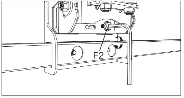
- Secure the front support [08] to arm assembly [02] using bolts [F2].
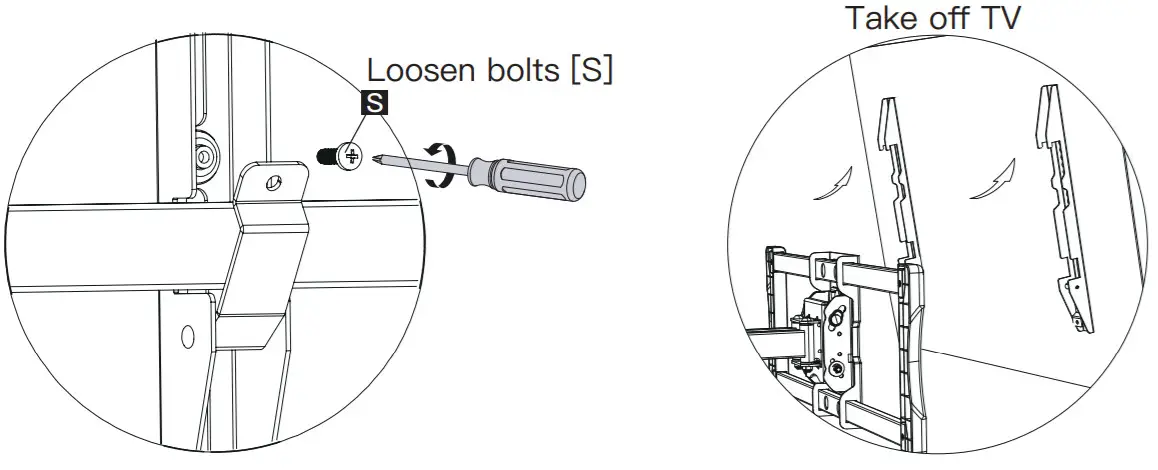
Step 5 Hang the TV onto the Front Support
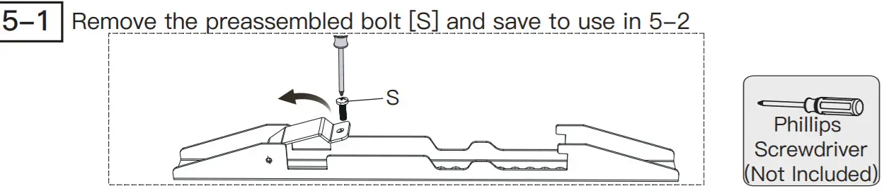
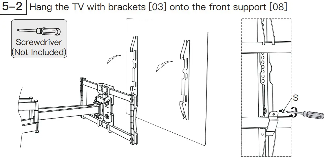
Press the safety locks down, then fasten the removed bolts [S]
![]() HEAVY! You may need assistance with this step.
HEAVY! You may need assistance with this step.
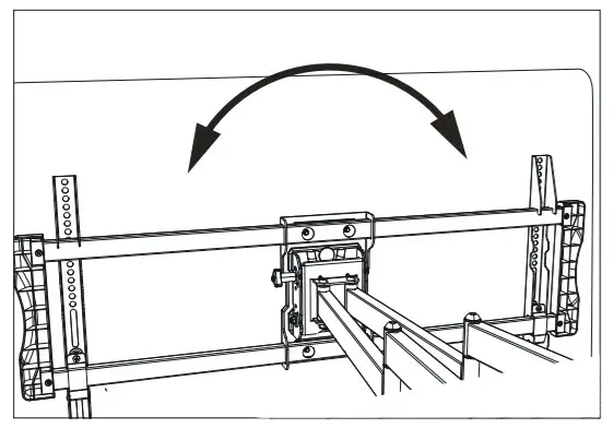
Step 6 Adjustments
 |
|
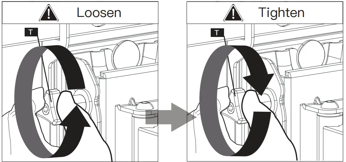
![]() CAUTION!
CAUTION! DO NOT over-loosen these four nuts when adjusting the level angle to prevent the TV from falling off.
- Loosen the bolt [F2] .

- Level your TV.
- Tighten the bolt [F2] to secure the TV in place.
 Note: Please take off the TV before shifting the arm assembly along the wall plate
To better position your mount and TV on your wall, the mount can be horizontal shifted left to right by following these steps.
- Loosen the bolts [F1].
- Shift the arm assembly [02] to your desired position.
- Tighten the bolts [F1] hard.
- Repeat the procedures in Step 5 to rehang and secure the TV onto the front support[08].
![]() Note: The bolts [F1] need to be tightened hard.
Note: The bolts [F1] need to be tightened hard.
![]() HEAVY! You may need assistance with this step.
HEAVY! You may need assistance with this step.
Thank you again for choosing this Perlesmith product!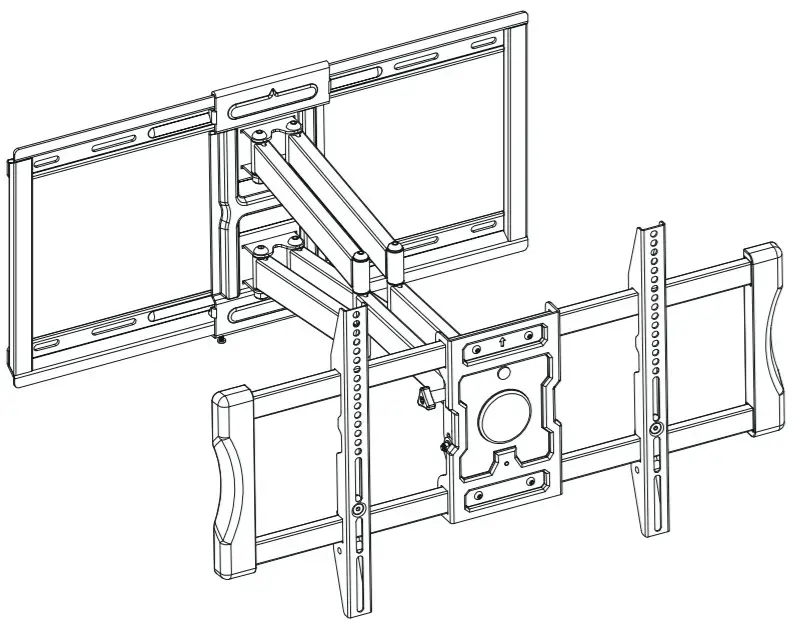
All of us at Perlesmith do appreciate your product purchase. We hope that you are as happy with your product as we designing and manufacturing it for you. We strive to provide you with the best quality products and services in the industry. Please share your experience of our product with others at www.perlesmith.com/pages/reviews if you are satisfied. If you have any questions please don’t hesitate to contact us at
Technical Support:1-800-556-6806 Mon-Fri 10am – 5pm (PST) (USA) (CAN)Other Info:[email protected] (US)[email protected] (CA)
 Please checkwww.perlesmith.comfor more products andcompany information.
Perlesmith offers products in these categories please remember us when you need one. Please remember us when you need one. Please remember us when you need one.
References
[xyz-ips snippet=”download-snippet”]