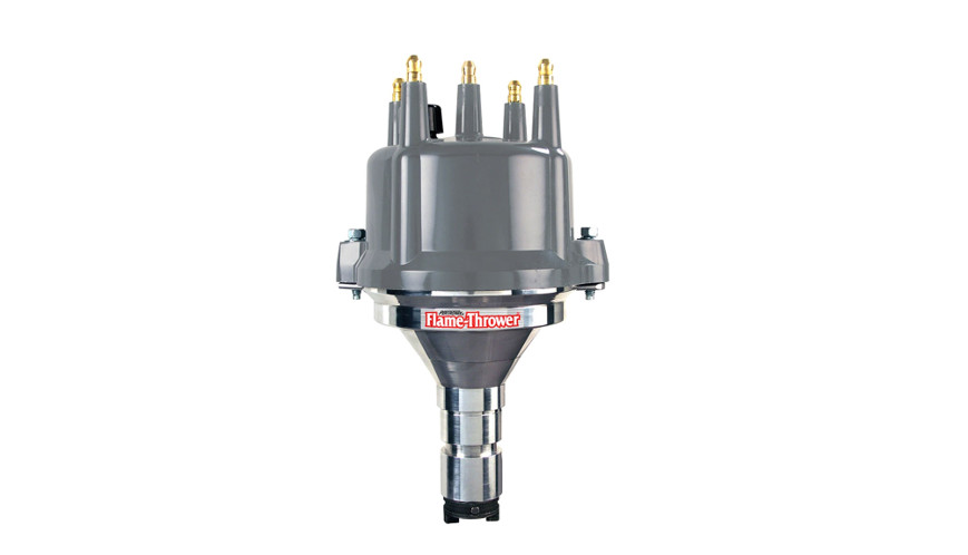
![]() Flame-Thrower Billet DistributorInstallation Instructions
Flame-Thrower Billet DistributorInstallation Instructions
GENERAL INFORMATION
IMPORTANT: Read all instructions before starting the installation.
- WARNING – DO NOT USE WITH SOLID CORE SPARK PLUG WIRES
- For 12-Volt NEGATIVE ground applications only. Maximum voltage 16V, Minimum voltage 8V.
- This distributor is equipped with a hardened steel gear, consult camshaft manufacturer for distributor gear compatibility.
- Engines that have been decked, had significant cylinder head milling or oil pump modification should be checked for oil pump bind and proper cam gear engagement prior to installation.
- Check spark plug wires ends to insure compatibility with distributor cap terminals.
- Modification to the advance curve or vacuum advance would render this product Illegal for Street or Off Highway use and may only be used for Closed Course Competition.
IGNITION TIMING BASICS
- Initial Timing – This is the base or timing of the engine at idle, before the vacuum or centrifugal advance begins.
- Centrifugal Advance – The centrifugal advance mechanism is made up of weights, springs and advance stops. The amount of advance and the rate of advance are determined by these parts of the distributor. Springs determine with the advance starts and the rate of advance. Advance stops, or limiters, determine the amount of advance.
- Total Timing – Combining the initial timing of the engine plus the amount of advance in the distributor is total timing. Generally this does not include the advance which the vacuum advance contributes. The total advance of an engine can be observed when the engine reaches a RPM higher then the rating of advance springs. Example: 10° Initial + 24°centrifugal = 34° Total Timing.
- Vacuum Advance – The vacuum advance is designed to add ignition timing when the vacuum signal is high. The vacuum canister should be connected to a ported vacuum source, which is located just above the throttle plates. At idle and full throttle there will be a very week vacuum signal at these locations. Generally part throttle and cruise conditions will produce a strong vacuum signal and timing will be added from the vacuum advance.
ADVANCE CURVES
This distributor is equipped with an advance curve that enables it to be used legally on vehicles outlined in the application guide. It is factory set at 24° of centrifugal advance and includes silver advance springs. Modification to the advance curve, mechanical or vacuum advance would render this product Illegal for Street or Off Highway use and may only be used for Closed Course Competition. Included with Flame-Thrower billet distributors are optional advance springs, limiters, and lockouts for the mechanical and vacuum advance. These accessories allow for the adjustment of the advance rate and total timing. When modifying the advance follow these basic guidelines:
- Use as much initial advance as possible without encountering excessive starter load.
- Select an advance curve that starts above the Idle RPM.
- If detonation (pinging) is detected, you have too much advance. If loss of power is detected you don’t have enough advance
- Advance springs can be mixed to create unique advance curves not presented on the chart.
- The distributor comes with 3 different sets of centrifugal advance limiters. The limiters limit the amount of centrifugal advance in the distributor to a designated. The limiters should only be used in special cases that require a reduced total timing. The limiters should be used in pairs but can be mixed to get the desired advance limit.
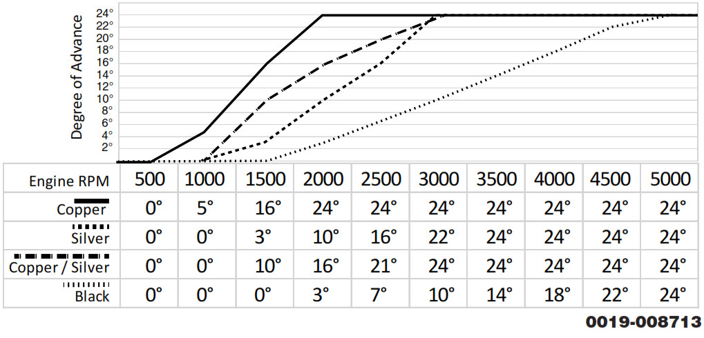
- Use the chart to the right to find an advance curve that meets your engines need. Select the parts that are indicated in the chart.

- To change out the advance springs, remove the cap and rotor.
- Use needle nose pliers to grip the looped end of each spring. Detach each spring from the inner and outer advance pins. Be care-ful not to overextend the spring so that it can be reused if needed.
- If advance limiters are to be used, they must be installed under the advance spring. (See illustration below)
- Install the desired spring/springs using the needle nose plier. Place one loop on the inner advance pin and stretch the spring care-fully to the outer advance pins.
- Reinstall the rotor and cap.Limiter marked with 6, limits the distributor advance to 12 degreesLimiter marked with 8, limits the distributor advance to 16 degreesLimiter marked with 10, llimits the distributor advance to 20 degrees
 Limiter marked with 6, limits the distributor advance to 12 degrees
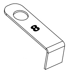 Limiter marked with 8, limits the distributor advance to 16 degrees
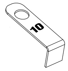 Limiter marked with 10, llimits the distributor advance to 20 degrees
VACUUM AND MECHANICAL ADVANCE LOCKOUT
Installation of the vacuum and mechanical advance lockouts requires removal of the distributor from the engine and partial disassembly of the distributor. These are optional modifications and should only be performed in specialized applications.
Mechanical Lockout Installation
- Remove the cap and rotor.
- Remove the advance springs, brass bushings, weights and limiters if used.
- Knock out the roll pin in the distributor gear, or retaining collar if equipped, on the shaft. Remove these from the distributor, take note of their respective locations for re-installation.
- Pull up on the center section of the distributor shaft and separate the shaft from the advance plate.
- Press the plastic mechanical advance lock down firmly in to the advance slot as shown in the illustration to the right.
- Line up the advance pin with the lockout and press it down.
- Reinstall the shims, gear or collar in the proper order and install the roll pin.
- The lock eliminates the need for advance springs weight and bushings.
 Vacuum Lockout Installation
- Remove the cap and rotor.
- Knock out the roll pin in the distributor gear, or retaining collar if equipped, on the shaft. Remove these from the distributor, take note of their respective locations for re-installation.
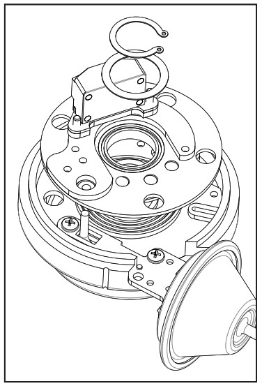
- Pull the entire distributor shaft and advance assembly out of the distributor housing.
- Remove the complete shaft assembly from the housing.
- Remove the snap ring and shim located on the center hub of the distributor.
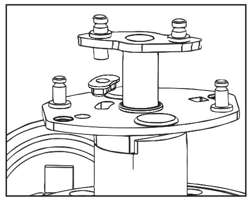
- Lift up on the entire module assembly to for access to the vacuum advance screws. Do not disconnect the ground wire.
- Remove the two screws holding down the vacuum advance. Remove vacuum advance from the distributor housing.
- Position the vacuum lockout into the housing. Reusing the screws to tighten the lockout in place.
- Position the module assembly first over the center hub and then over the vacuum lockout pin. Once aligned press plate down.
- Reinstall the shim and snap ring around the center hub.
- Insert the distributor shaft assembly, all shims, gear and or collars. Be sure the mechanical advance is seating flat across the top. Install the roll pin and verify the shaft end-play is appropriate
- Reinstall rotor and distributor cap.
DISTRIBUTOR INSTALLATION
- Label original distributor power wires any tachometer wire if present. Disconnect the wires and vacuum advance hoses.
- Remove the distributor cap. Turn the engine over until the rotor contact is aimed at a fixed point on the engine or firewall. Note this position by using tape or a mark.
- Place the distributor cap back on and note which plug wire the rotor is pointing to. Now label all the other spark plug wires and remove the distributor cap.
- Loosen the distributor hold down clamp and remove the clamp from the engine.
- Lift the distributor out of the engine. On applications that use a gear the rotor will rotate as the distributor is lifted out. This will need to be taken into consideration when installing the new distributor.
- Remove the distributor cap from the Flame-Thrower distributor.
- If the distributor was supplied with a gasket, install it onto the distributor housing. Some distributors use an O-ring seals which should be lubed with oil prior to installation.
- Apply assembly lube or moly grease to the distributor gear if equipped.
- Install the distributor making sure the rotor lines up with the fixed mark on the engine.If the distributor does not fully seat, the oil pump shaft may need to be rotated until the rotor lines up with the fixed mark. (The oil pump drive can be turn by hand with an extended reach screw driver).
- Position and tighten the distributor hold down clamp. In many cases the distributor hold down clamp is the primary ground path for the ignition. The clamp be clean of paint, chrome, etc.
- Install the distributor cap and attach the spark plug wires one at a time. Verify that the firing order is correct for your specific application.
WIRING
- Many vehicles came factory equipped with a ballast resistor or resistance wire. To achieve optimum performance we recommend the removal of all external resistance. This will allow full battery voltage to be supplied to the coil and distributor. Use the PerTronix ignition power relay PN# 2001 to simplify the bypassing of resistors and the rewiring process.
- Flame-Thrower billet distributors can be used with coils ranging in primary resistance between 0.6 ohms and 3.5 ohms. Do not use coils with a primary resistance less then .06 ohm, unless an external ignition box is used with the distributor. In this case follow the box manufactures coil recommendations.
- The distributor wires can be cut to length to meet you applications needs. If additional wire length is needed, properly splice the wire using 20 gauge wire. Do not exceed 48″ of wire. For ultra flexible silicone wire, use PerTronix wire extension kit PN# 2005
- Follow the wiring diagrams that matches your applications.
- Tachometers should hook to the same location as stock. Applications which use an external ignition box should use the BLACK wire as the trigger wire. The RED wire should be connected to a 12V source controlled by the key. Make sure the source has power in both the start and run mode.

START UP
- Check all the wires and connections to ensure they are correct.
- Verify the spark plug wires are securely connected and in the correct firing order.
- Start the engine. If the engine fails to start, rotate the distributor in small increments clockwise or counterclockwise until the engine starts.
- Bring the engine up to normal operating temperature.
- Disconnect the vacuum advance hose to the distributor and plug the hose.
- Set initial timing to the desired setting.
TROUBLESHOOTING
For the most up-to-date troubleshooting tips, wiring diagrams, and FAQ’s visit www.support.pertronix.com. The most common issues can be found below.Q. The engine will not start.A. There are several reasons that can prevent the engine from starting after installing a distributor.
- Check all connections to ensure that they are tight and in the proper locations.
- Check the engine timing to ensure the distributor was installed correctly.
- Make sure the distributor’s Red wire is getting full battery voltage with the key in the start and run position.
- Check that the distributor housing is getting a good ground back to battery negative.
- Remove all other wires from the coil negative except for the distributor’s Black wire. Turn the key “ON” and check the coil positive for voltage. If the coil does not have voltage the coil was wired incorrectly. If the coil positive terminal has voltage, try starting the engine. If the engine starts then one of the wires removed from the coil negative terminal is shorted to ground.
Q. The engine starts but stops after a period of time. Typically after a cool down it will start up again.A. This type of problem can occur after a few minutes from startup to hours. The most common reason is a reduced voltage to the distributor Red wire. Visit ww.support.pertronix.com and perform the loaded voltage test.Q. How do I check a coils primary resistance.A. For the most accurate results use a digital voltmeter. Select the lowest ohm scale and measure between the positive and negative terminals. The coil should not have any wires attached to if while being tested.
LIMITED WARRANTY
PerTronix, LLC. warrants to the original Purchaser of its Flame-Thrower distributor that the product shall be free from defects in material and workmanship (normal wear and tear excluded) for a period of 1 year for mechanical and 30 months for electrical from the date of purchase.If within the period of the foregoing warranty PerTronix finds, after inspection, that the product or any component thereof is defective, PerTronix will, at its option, repair such products or component or replace them with identical or similar parts PROVIDED that within such period Purchaser:
- Promptly notifies PerTronix, in writing, of such defects.
- Delivers the defective product or component to PerTronix (Attn: Warranty) with proof of purchase date; and
- Has installed and used the product in a normal and proper manner, consistent with PerTronix printed instructions
THE FOREGOING LIMITED WARRANTY IS EXCLUSIVE AND IN LIEU OF ALL OTHER WARRANTIES, WHETHER EXPRESS OR IMPLIED, INCLUDING ANY IMPLIED WARRANTY OF MERCHANTABILITY OR FITNESS FOR A PARTICULAR PURPOSE.THE FURNISHING OF A REPAIR OR REPLACEMENT COMPONENT OR COMPONENTS SHALL CONSTITUTE THE SOLE REMEDY OF PURCHASER AND THE SOLE LIABILITY OF PerTronix WHETHER ON WARRANTY, CONTRACT OR FOR NEGLIGENCE AND IN NO EVENT WILL PerTronix BE LIABLE FOR MONEY DAMAGES WHETHER DIRECT OR CONSEQUENTIAL.![]()
440 East Arrow HighwaySan Dimas, CA 91773909-599-5955www.pertronixbrands.com
References
[xyz-ips snippet=”download-snippet”]