![]()
PetSafe Little Dog Deluxe In-Ground Fence User Guide

PIG20-11041
Please read this entire guide before beginning
IMPORTANT SAFETY INFORMATION
Explanation of Attention Words and Symbols used in this guide
![]() This is the safety alert symbol. It is used to alert you to potential personal injury hazards. Obey all safety messages that follow this symbol to avoid possible injury or death.
This is the safety alert symbol. It is used to alert you to potential personal injury hazards. Obey all safety messages that follow this symbol to avoid possible injury or death.
![]() WARNING
WARNING
WARNING indicates a hazardous situation which, if not avoided, could result in death orserious injury.
![]() CAUTION
CAUTION
CAUTION, used with the safety alert symbol, indicates a hazardous situation which, if not avoided, could result in minor or moderate injury.
CAUTION
CAUTION, used without the safety alert symbol, indicates a hazardous situation which, if not avoided, could result in harm to your pet.
NOTICE
NOTICE is used to address practices not related to personal injury.
![]() WARNING
WARNING
- Not for use with aggressive dogs. Do not use this product if your dog is aggressive or if your dog is prone to aggressive behaviour. Aggressive dogs can cause severe injury. If you are not sure that this product is right for your dog, please talk to your veterinarian or a certified trainer.
- Underground cables can carry high voltage. Have all underground cables marked before youdig to bury your wire. In most areas, this is a free service.
- Do not install, connect, or remove your system during a lightning storm. If the storm is close enough for you to hear thunder, it is close enough to create hazardous surges.
- Follow all safety instructions for your power tools. Be sure to always wear your safety goggles.
- Risk of Electric Shock. Use the Fence Transmitter indoors in a dry location only.
- DO NOT attempt to cut into or pry open the battery. Be sure to discard the used battery properly.
![]() CAUTION
CAUTION
- Risk of injury. Wire on top of the ground may be a trip hazard. Use care in how you placeyour wires.
- This system is NOT a solid barrier. The system is designed to act as a deterrent to remind pets by Static Stimulation to remain in the boundary established. It is important that you reinforce training with your pet on a regular basis. Since the tolerance level to Static Stimulation varies from pet to pet, Radio Systems Corporation CANNOT guarantee that the system will, in all cases, keep a pet within the established boundary. Not all pets can be trained to avoid crossing the boundary! Therefore, if you have reason to believe that your pet may pose a danger to others or harm himself if he is not kept from crossing the boundaries, you should NOT rely solely upon the system to confine your pet. Radio Systems Corporation shall NOT be liable for any property damage, economic loss or any consequential damages, sustained as a result of any animal crossing the boundary.
- This product is not a toy. Keep it away from the reach of children.
CAUTION
- Please read and follow the instructions in this manual. Proper fit of the collar is important. A collar worn for too long or made too tight on the pet’s neck may cause skin damage. This is called bed sores; it is also called decubitus ulcers or pressure necrosis.
- Avoid leaving the collar on the dog for more than 12 hours per day.
- When possible reposition the collar on the pet’s neck every 1 to 2 hours.
- Check the fit to prevent excessive pressure; follow the instructions in this manual.
- Never connect a lead to the electronic collar; it will cause excessive pressure on the contacts.
- When using a separate collar for a lead, don’t put pressure on the electronic collar.
- Wash the dog’s neck area and the contacts of the collar weekly with a damp cloth.
- Examine the contact area daily for signs of a rash or a sore.
- If a rash or sore is found, discontinue use of the collar until the skin has healed.
- If the condition persists beyond 48 hours, see your veterinarian. For additional information on bed sores and pressure necrosis, please visit our website. These steps will help keep your pet safe and comfortable. Millions of pets are comfortable while they wear stainless steel contacts. Some pets are sensitive to contact pressure. You may find after some time that your pet is very tolerant of the collar. If so, you may relax some of these precautions. It is important to continue daily checks of the contact area. If redness or sores are found, discontinue use until the skin has fully healed.
- You may need to trim the hair in the area of the Contact Probes. Never shave the dog’s neck; this may lead to a rash or infection.
- You should not make the collar any tighter than is required for good contact. A collar that is too tight will increase the risk of pressure necrosis in the contact area.
- Proper training of your pet is essential to the success of the Petsafe® Little Dog Deluxe In-Ground Fence™. During the first 2 weeks of training, do not use the training device on your pet without direct supervision.
- To prevent an unintended stimulation:– The receiver collar should not be on your dog when the system is tested.– Remove the receiver collar before making any changes to your system.– Before placing the receiver collar on your pet, test the boundary location and width after any change.
- If possible, do not use an outlet protected with a residual current device (RCD) or ground fault circuit interrupter (GFCI). The fence system will function properly, but in rare cases, nearby lightning strikes may cause the RCD or GFCI to trip. Without power, your pet may be vulnerable to escape. You will have to reset the RCD or GFCI to restore power to the system.
NOTICE
- Avoid damage to the insulation of the loop wire during the install; damage may cause areas of weak signal and lead to early failure of the loop (wire breaks).
- Use care when mowing or trimming your grass not to cut the loop wire.
- For added protection for the Fence Transmitter when unused for long periods of time or prior to thunderstorms, disconnect the Loop Boundary Wires and unplug the Power Adaptor from the outlet. This will prevent damage to the Transmitter due to surges.
Thank you for choosing PetSafe®. You and your pet deserve a companionship that includes memorable moments and a shared understanding together. Our products and training tools promote a lifestyle of protection, teaching, and love — essentials that influence memories for a lifetime. If you have any questions, please contact the Customer Care Centre. For alisting of Customer Care Centre telephone numbers, visit our website at www.petsafe.com.
To get the most protection out of your warranty, please register your product within 30 days at www.petsafe.com. By registering, and keeping your receipt, you will enjoy the product’s full warranty and should you ever need to call the Customer Care Centre we will be able to help you faster. Most importantly, PetSafe® will never give or sell your valuable information to anyone. Complete warranty information is available online at www.petsafe.com.
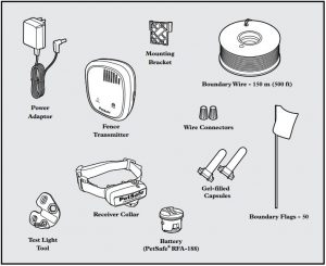
In the Box
Other Items You May Need
- Additional wire and flags (PRFA-500)
- Tape measure
- Small Phillips screwdriver
- Drill & mounting hardware
- Shovel or lawn edger
- Pliers
- Wire stripping pliers
- Scissors
- Additional wire connectors
- Ground rod and clamp
- Waterproofing compound (e.g. silicone caulk)
- PVC pipe or water hose
- Circular saw with masonry blade
- Staple gun
- Non-metallic collar and lead
- Lighter
How the System Works
A radio signal travels from the Fence Transmitter through a buried wire, marking the boundaries you wish to set for your dog. Your dog wears a Receiver Collar that detects the signal at the boundary. As your dog approaches the boundary, the receiver issues a warning tone. If he proceeds further, he receives a safe but startling Static Stimulation. While harmless, the stimulation will persuade him to stay in the containment area you’ve established. Boundary flags are a temporary visual aid for your pet; remove them after training. This Little Dog Deluxe In-Ground Fence™ has been proven safe, comfortable, and effective for pets over 2.3 kg (5 pounds), neck sizes 15 cm to 40 cm (6″ to 16″).
Key Definitions
- Fence Transmitter: The device that transmits the radio signal through the Boundary Wire.
- Pet Area: The area within the Warning Zone where your pet can roam freely.
- Warning Zone: The outer edge of the Pet Area where your pet’s Receiver Collar begins to beep, warning him not to go into the Static Stimulation Zone.
- Static Stimulation Zone: The zone beyond the Warning Zone where your pet’s Receiver Collar will emit a Static Stimulation, signaling him to return to the Pet Area.
- Boundary Width: The combination of the Warning Zone and the Static Stimulation Zone.
- Receiver Collar: The device that receives the radio signal from the Boundary Wire.
- Stimulation Level Button: The button to adjust the level of Static Stimulation your pet receives in the Static Stimulation Zone.
- Receiver Indicator Light: The light that indicates the level of stimulation at which the Receiver Collar is set. This light also serves as a low battery indicator.
- Contact Points: The contacts through which the Receiver Collar delivers the safe Static Stimulation when your pet moves into the Static Stimulation Zone.
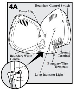
- Power Socket: Where the Power Adaptor plugs into the Fence Transmitter. The Fence Transmitter is powered by a standard outlet.
- Boundary Control Switch: The switch to adjust according to the length of Boundary Wire used.
- Ground Terminal: The terminal where the Ground Wire connects to the Fence Transmitter.
- Boundary Wire Terminals: The terminals where the Boundary Wires connect to the Fence Transmitter in order to complete a continuous loop.
- Loop Indicator Light: The light that indicates that the Boundary Wire makes a complete loop, enabling the signal to be transmitted.
- Boundary Width Control: The knob that adjusts the width of the Warning and Static Stimulation Zones. Note: Adjusting the knob does not change the level of Static Stimulation on the Receiver Collar.

OPERATING GUIDE
STEP 1: Locate the Fence Transmitter
Place the Fence Transmitter:
- In a dry, well ventilated, protected area (1A, 1B).
- In an area where temperatures do not fall below freezing (e.g., garage, basement, shed, closet).
- Secured to a stationary surface using the mounting hardware. A mounting template is included in the back of this guide.
- At least 1 m (3 ft) from large metal objects or appliances as these items may interfere with the signal consistency (1C).
To mount the Fence Transmitter, screw the mounting bracket onto a stationary surface such as a wall, and slide the Fence Transmitter onto the bracket. Once you have mounted the Fence Transmitter, the Boundary Wire must exit the building. This can be accomplished via a window or through a hole drilled through the wall. Ensure the drill path is clear of any utilities. Make sure the Boundary Wire is not cut off or pinched by a window, door, or garage door, as this can damage it over time.
To prevent fires and electrical hazards, install the Fence Transmitter in buildings that are in accordance with state and local electrical codes.
![]()
STEP 2: Lay Out the System
Basic Planning Tips
![]() Warning: Underground cables can carry high voltage. Have all underground cables marked before you dig to bury your wire. In most areas this is a free service. Avoid these cables when you dig.
Warning: Underground cables can carry high voltage. Have all underground cables marked before you dig to bury your wire. In most areas this is a free service. Avoid these cables when you dig.
For information regarding how these underground wires can affect your system’s operation, see Step 3 Position the Boundary Wire.
- The Boundary Wire MUST start at the Fence Transmitter and make a continuous loop back (2A).
- Twisting two sides of the Boundary Wire cancels the signal and allows your pet to cross over that area safely. Plastic or metal piping will not cancel the signal. Twist the Boundary Wire 30 times per metre (10 times per foot) to cancel the signal (2A).
- Design a layout that is suitable for your property. Sample layouts are provided in this section, and a grid for designing your layout is provided in the back of this guide.
- Always use gradual turns at the corners with a minimum 1 m (3 ft) radius, to produce a more consistent boundary (2B). Do not use sharp turns, as this will cause gaps in your boundary.
- To properly contain your pet, we recommend setting a Boundary Width for the Warning and Static Stimulation Zones to approximately 4 m to 7 m (2 m to 3.5 m on each side of the wire).

- Avoid making passageways too narrow for your pet to move about freely (e.g., along the sides of a house).
- The Receiver Collar can be activated inside the house if the Boundary Wire runs along the outside wall of the house. If this occurs, remove your pet’s Receiver Collar before bringing him inside, decrease the range using the Boundary Width Control knob or consider an alternative layout.
Sample Layouts
Sample 1: Perimeter Loop (Single Loop)
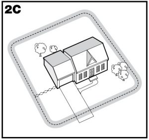
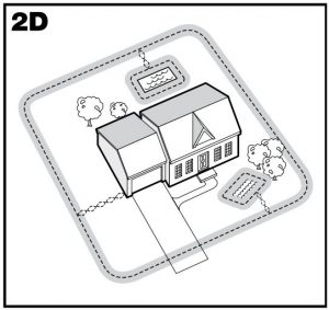
The Perimeter Loop is the most common layout. This will allow your pet to freely and safely roam your entire property (2C). It can also protect pools and landscaping (2D
Sample 2 (2E): Perimeter Loop Using Existing Fence (Single Loop)

This layout allows you to include your existing fence as part of your layout and keep your pet from jumping out or digging under your existing fence. It reduces the amount of wire which will need to be buried. From the Fence Transmitter, run the wire to A, A to B, B to C, C to D, D to E, E to A, twist the wires from A back to the Fence Transmitter. See the “Install the Boundary Wire” section for more information on attaching the wire to a fence.
Double LoopA Double Loop must be used when you are not establishing the Boundary Zone on all sides of your property.
When using a Double Loop, the Boundary Wire must be separated by a minimum of 1.5 m (5 ft) to avoid canceling the signal. Remember that a Double Loop will require twice as much wire.
Sample 3 (2F): Front or Back Property Only (Double Loop)

From the Fence Transmitter, run the wire to A, A to B, B to C, C to D, D to E, E to F, make a U-turn and follow your path all the way back to A, keeping the wire separated at least 1.5 m (5 ft). Twist the wire from A back to the Fence Transmitter.
Sample 4 (2G): Front Boundary Only (Double Loop)
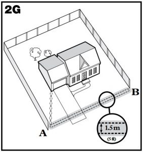
From the Fence Transmitter, run the wire to A, A to B, B back to A keeping the wire separated at least 1.5 m (5 ft). Twist the wire from A back to the Fence Transmitter.
Sample 5 (2H): Lake Access (Double Loop)

From the Fence Transmitter, run the wire to A, A to B, make a U-turn and go to C, C to D, D to E, make a U-turn and follow your path all the way back to A keeping wire separated at least 1.5 m (5 ft). Twist the wire from A back to the Fence Transmitter.
Sample 6 (2I): Wire Loop Attached to Existing Fence (Double Loop)
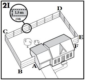
This layout allows you to include your existing fence as part of your layout and keep your pet from jumping out or digging under your existing fence. It reduces the amount of wire which will need to be buried. Run the wire from the Fence Transmitter to A, A to B, B to C, C to D, D to E, E to F, make a U-turn and follow your path all the way back to A, keeping the wire separated at least 1.5 m (5 ft). Twist the wire from A back to the Fence Transmitter. See the “Install the Boundary Wire” section for more information on attaching the wire to a fence.
STEP 3: Position the Boundary Wire
Lay out the Boundary Wire using your planned boundary and test the system BEFORE burying the wire or attaching it to an existing fence. This will make any layout changes easier. Work carefully. A nick in the wire insulation can diminish the signal strength and create a weak area where your pet can escape.
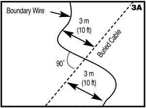
Running the Boundary Wire parallel to and within 3 m (10 ft) of electrical wires, neighbouring containment systems, telephone wires, television or antenna cables, or satellite dishes may cause an inconsistent signal. If you must cross any of these, do so at 90-degree angles (perpendicularly) (3A).
If separating the wire by at least 3 m (10 ft) from a neighbouring containment system’s wire does not reduce the inconsistent signal, contact the Customer Care Centre.
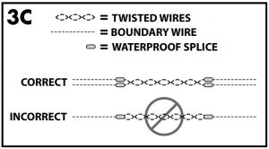
Twisting and Connecting the Boundary Wire
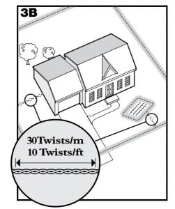
Twisting the Boundary Wire cancels the signal and allows your pet to cross over that area safely (3B). The signal cannot be cancelled by running the wire through plastic or metal piping. Using shielded cable in place of the Boundary Wire will also not cancel the signal. Refer to figure (3C) for the correct method of twisting the wire. You can twist your own wire by cutting two equal lengths of Boundary Wire supplied and twisting them together. Anchor one end of the wires to something secure and insert the other end in a power drill. Pull the wire taut. The drill enables you to twist the wire quickly. Twist the Boundary Wire 30 to 36 times per metre (10 to 12 times per foot) to cancel the signal. Once you have completed your boundary layout connect one end of the twisted wire to the Perimeter Loop and see Step 4 to connect the other end of the twisted wire to the transmitter. If your layout includes a Secondary Loop to protect landscapingor pool areas, connect the twisted wire between the Perimeter Loop and the Secondary Loop.
To Splice or Repair the Boundary Wire
If you need additional Boundary Wire to expand your wire loop, you will need to splice the wirestogether. Note the locations of all splices for future reference.
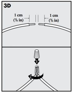
Strip approximately 1 cm (3/8″) of insulation off the ends of the Boundary Wires to be spliced (3D). Make sure the copper Boundary Wire is not corroded. If the Boundary Wire is corroded, cut it back to expose clean copper wire.
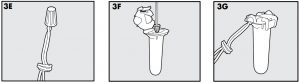
Insert the stripped ends into the wire connector and twist the wire connector around the wires. Ensure that there is no copper exposed beyond the end of the wire connector. Tie a knot 7.5 cm to 10 cm (3″ to 4″) from the wire connector (3E). Ensure that the wire connector is secure on the wire splice.
Once you have securely spliced the wires together, open the lid of the gel-filled splice capsule and insert the wire connector as deeply as possible into the waterproof gel inside the capsule (3F). Snap the lid of the capsule shut (3G). For proper system performance, the splice connection must be waterproof.
If your splice pulls loose, the entire system will fail. Make sure your splice is secure. Additional gel-filled splice capsules and wire connectors are available through the Customer Care Centre.
Additional Boundary Wire

Extra direct burial Boundary Wire can be purchased in 150 m (500 feet) spools at the store where you purchased the kit or through the Customer Care Centre.
Note: When adding Boundary Wire, it must act as a continuous loop.
The table at right indicates the approximate length of Boundary Wire needed for a square, Single Loop layout. Length will vary due to the amount of twisted wire and layout used.
STEP 4: Connect the Wires to the Fence Transmitter
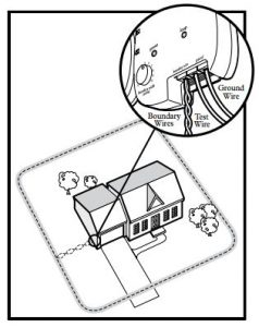
Boundary Wire (4A)
- Run the Boundary Wire to the Fence Transmitter through a window, under a door, through a crawl space vent, or any other appropriate available access. You can also drill a hole through your wall.
- Strip the ends of the Boundary Wire approximately 1.3 cm (1/2″).
- Insert the Boundary Wires into the Boundary Wire Terminals on the Fence Transmitter. Make sure wires do not touch each other at the terminals.
- Turn the Boundary Width Control knob to 10. This will set the Warning Zone at themaximum width.
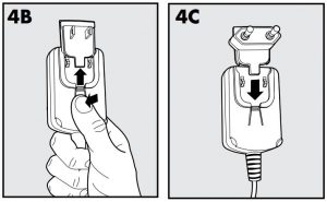
- Plug the Power Adaptor into the Power Socket and a working outlet. The Power Adaptor comes with the North American plug installed and additional plugs for the UK, Europe, and Australia. To change the plug:
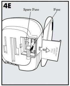
 a. Push in the tab on the Power Adaptor and remove the plug by sliding it off as shown (4B).b. Slide the proper plug for your electrical outlet onto the Power Adaptor as shown (4C).
 - The Power Light and Loop Indicator Lights should come on. If this does not happen, see the “Troubleshooting” section.
 a. Push in the tab on the Power Adaptor and remove the plug by sliding it off as shown (4B).b. Slide the proper plug for your electrical outlet onto the Power Adaptor as shown (4C).
Ground Wire (4D)
 Proper grounding, although not necessary for the system to work, will help reduce the chance of electrical surges causing damage to your Fence Transmitter and/or Power Adaptor. To ground your unit, you will need a solid (not stranded) Ground Wire (14 to 18 gauge insulated copper wire) and a ground rod with clamp, which may be obtained at most electrical supply stores. Connect one end of the Ground Wire to the Ground Terminal located on the Fence Transmitter and the other end of the Ground Wire to the ground rod. The ground rod must be buried at least 90 cm (3 ft) into the ground and located as close as possible to the Fence Transmitter.
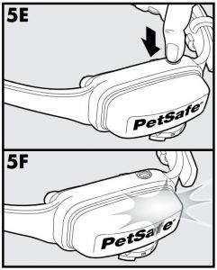
Fuse Protection (4E)
The Fence Transmitter is also equipped with a 250 volt, ½ amp fuse to protect the unit’s electronic circuitry from electrical power surges. To locate the fuse, slide off the lid on the back of the Fence Transmitter. A spare fuse is also provided.
![]() WARNING:
WARNING:
- Do not install, connect, or remove your system during a lightning storm. If the storm is close enough for you to hear thunder, it is close enough to create hazardous surges.
- Risk of electric shock. Use the Fence Transmitter indoors in dry location only.
CAUTION
If possible, DO NOT use an AC circuit protected with a Ground Fault Circuit Interrupter (GFCI) or Residual Current Device (RCD). In rare cases, nearby lightning strikes may cause the GFCI or RCD to trip. Without power your dog may be vulnerable to escape. You will have to reset the GFCI or RCD to restore power to the system.
NOTICE
For added protection, when unused for long periods of time or prior to thunderstorms, unplug from the wall outlet and disconnect the loop boundary wires. This will prevent damage to the transmitter due to surges.
STEP 5: Prepare the Receiver Collar
To Insert and Remove the BatteryNote: Do not install the battery while the Receiver Collar is on your pet.This Receiver Collar utilizes a replaceable PetSafe® battery (RFA-188). This unique battery is designed to make battery replacement easier and increase water protection.


To activate the collar, insert the battery module (5A). Using the edge of the Test Light Tool as shown, turn the battery clockwise until the vertical line on the battery is pointed to the “ON” position (5B). If the PetSafe® Receiver Collar is not going to be used on the pet immediately, leave it in the “OFF” position.
To remove the battery, turn the battery counter-clockwise using the edge of the Test Light Tool as shown (5C, 5D).
Discharge all power by holding the Stimulation Level Button down until the light is no longer illuminated. Replace with a new battery.
![]() WARNING: DO NOT attempt to cut into or pry open the battery. Be sure to discard the used battery properly.
WARNING: DO NOT attempt to cut into or pry open the battery. Be sure to discard the used battery properly.
A replacement PetSafe® battery can be found at many retailers. Contact the Customer Care Centre or visit our website at www.petsafe.com to locate a retailer near you.
Static Stimulation and Battery Test FeatureWhen the RFA-188 Battery Module is first installed in the receiver, the red LED will flash the current stimulation level setting (1 to 5). For the next 30 seconds, the receiver will monitor the battery status and will either flash the green LED once every 5 seconds to indicate a good battery, or flash the red LED once every 5 seconds to indicate a low battery condition. After the 30 second battery test period, the green LED will cease to flash if the battery is good. If the battery was low during the test period, the red LED will continue to flash at a rate of 1 flash every 20 seconds to indicate a low battery condition. In this situation, battery replacement is recommended.
To Set the Static Stimulation LevelRead all steps before attempting to set the Static Stimulation Level.
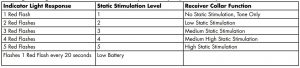
- With the battery installed, press the Stimulation Level Button and release when the ReceiverIndicator Light lights red (5E).
- The Receiver Indicator Light will emit a number of red flashes representing the StaticStimulation Level (5F).
- Increase the Static Stimulation Level by pressing and releasing the Stimulation Level Button within 5 seconds of the previous flashes.
The Static Stimulation Levels increase from 1 to 5. Pushing the Stimulation Level Button while the Receiver Collar is on level 5 will cause the Receiver Collar to revert to level 1. Refer to the Function and Response Table to choose the Static Stimulation level that best fits your pet.The Receiver Indicator Light acts as a low battery indicator, flashing every 20 seconds when battery replacement is required.
Anti-Linger PreventionThe Anti-Linger Prevention feature keeps your dog from staying in the Warning Zone for long periods of time and draining the Receiver Collar battery. Your dog will hear a warning tone when he reaches the Warning Zone. If your dog does not return to the Pet Area after two seconds, he will receive a continuous Static Stimulation until he returns to the Pet Area.
Run Through PreventionThis system includes a unique “run-through” prevention so that your dog cannot escape the Pet Area without receiving an increased level of Static Stimulation. The Receiver Collar automatically increases the Static Stimulation when your dog continues more than 20% of the way through the pet fencing Boundary Width. For example, if the signal is detected 3 metres from the wire and your dog enters the Static Stimulation Zone, this feature is activated when he is approximately 2.4 metres from the Boundary Wire. Your dog will then receive a Static Stimulation that is at an increased level corresponding to the Static Stimulation level setting on the Receiver Collar. The Receiver Collar is equipped to automatically increase the level of Static Stimulation the longer your pet remains in the Static Stimulation Zone if the collar is set at level 2 or above.
Over Stimulation ProtectionIn the unlikely event that your pet “freezes” in the Static Stimulation Zone, this feature limits the Static Stimulation duration to a maximum of 30 seconds. While the system locks out further Static Stimulation, the warning tone will continue until the pet leaves the Static Stimulation Zone.
Function and Response Table
Note: Begin training with Static Stimulation Level 2 and only increase if your pet does not respond to the Static Stimulation.
STEP 6: Set the Boundary Width and Test the Receiver Collar
With the Boundary Wire in place and properly connected, it is time to set the containment field and test the system.
CAUTION: The Receiver Collar should NOT be on your dog when the system is tested.
Note: The Receiver Collar is waterproof, which can make the tone hard to hear.The flashing Test Light when held to the Contact Points indicates the Receiver Collar is delivering Static Stimulation.
To best utilize the automatic Run-Through Prevention feature, the containment Boundary Width should extend at least 1.8 m to 3 m (6 ft to 10 ft) on each side of the Boundary Wire (total Boundary Width of 3.7 m to 6 m (12 ft to 20 ft).

- Apply Power to the Fence Transmitter with the supplied Power Adaptor.
- Set the Boundary Width Control Switch (located on the side of the Fence Transmitter) (6A)to the A, B, or C setting based on the total length of Boundary Wire used. Setting B is usedfor most properties. The following table will indicate the proper setting.
- The width of the containment field is adjusted using the transmitter’s Boundary WidthControl knob. Turn the knob counter clockwise until the alarm sounds and the Loop Indicator Light is no longer lit. Turn the knob clockwise and increase by 2 numbers. The alarm should turn OFF and the light should turn ON. CAUTION: The receiver collar should not be on your dog when the system is tested. Your pet may receive an unintended stimulation.
- Place battery in Receiver Collar and turn ON. The Receiver Collar will cycle through the Static Stimulation and Battery Status feature as described in Step 5. To identify the Warning and Static Stimulation Zones make sure the Receiver Collar is set at level 5 (see Step 5).
- Test the Boundary Width of the system by selecting a section of straight Boundary Wire that is at least 15 metres (50 feet) long. Start inside the centre of the containment field.
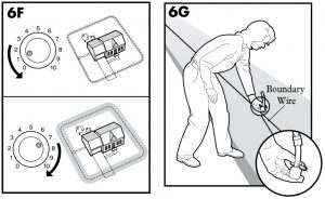
- Place the Test Light Tool Contacts on the Contact Points on the Receiver Collar (6B, 6C). Hold the Receiver Collar at your dog’s neck height with the Contact Points pointing up (6D) and the Stimulation Level Button facing the Boundary Wire. Slowly walk toward the Boundary Wire until you hear the warning tone (6E). When you hear the warning tone, you have identified the Boundary Width distance (Static Stimulation Zone).Two seconds after the warning tone, the test light will begin to flash. This flashing light can aid you in identifying the Boundary Width should you have difficulty hearing the tone. To avoid having the Receiver Collar go into Over Stimulation Protection mode, walk back into the Pet Area until the beeping stops. If the Receiver Collar does not beep at the desired range, adjust the Boundary Width Control knob to obtain the desired range. Turning the Boundary Width Control knob clockwise increases the Boundary Width while turning it counterclockwise decreases it (6F). Repeat this activity as needed until the Receiver Collar beeps between 1.8 m to 3 m (6 ft to 10 ft) from the Boundary Wire. If using a Double Loop layout, you may need to increase the separation of the Boundary Wire and/or increase the size of the Boundary Width to achieve the desired range.
- Test in a number of different locations around the containment area until you are satisfied that the system is functioning properly.
- Next, walk all around the Pet Area to ensure there are no areas where the Receiver Collar may activate from signals coupled onto buried wires or cables. Test the collar in and around the inside of the house as well. As mentioned, cable and wires from cable TV, electrical or telephone lines may conduct pet fencing signals inside and outside the house that can activate the dog’s collar accidentally. While rare, if this occurs your Boundary Wire is probably too close to these outside lines and should be moved or modified as shown in Figure 3A.
- To test the run-through prevention feature, walk towards the Boundary Wire. The Receiver Collar should tone and the Test Light should flash brighter as you enter the run-through area (6G).
 CAUTION: The receiver collar should not be on your dog when the system is tested. Your pet may receive an unintended stimulation.
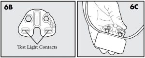

 If the Receiver Collar does not beep at the desired range, adjust the Boundary Width Control knob to obtain the desired range. Turning the Boundary Width Control knob clockwise increases the Boundary Width while turning it counterclockwise decreases it (6F). Repeat this activity as needed until the Receiver Collar beeps between 1.8 m to 3 m (6 ft to 10 ft) from the Boundary Wire. If using a Double Loop layout, you may need to increase the separation of the Boundary Wire and/or increase the size of the Boundary Width to achieve the desired range.
If you are satisfied that your system is functioning properly, you are ready to start burying the Boundary Wire. If the Receiver Collar did not beep or the Test Light did not flash, see the “Troubleshooting” section.
STEP 7: Install the Boundary Wire
NOTICE: Before you begin installing the Boundary Wire, unplug the Fence Transmitter power adaptor from the outlet.
To Bury the Boundary WireBurying the Boundary Wire is recommended to protect it and prevent disabling the system.
- Cut a trench 2.5 cm to 7.6 cm (1 in to 3 in) deep along your planned boundary.
- Place the Boundary Wire into the trench maintaining some slack to allow it to expand and contract with temperature variations.
- Use a blunt tool such as a wooden paint stick to push the Boundary Wire into the trench. Be careful not to damage the Boundary Wire insulation.
To Attach the Boundary Wire to an Existing FenceThe Boundary Wire of the Little Dog Deluxe In-Ground Fence™ can be attached to a chain link fence, split rail fence, or a wooden privacy fence. The Boundary Wire can be attached as high as needed. However, make sure the Boundary Width is set at a high enough range for the pet to receive the signal. If using a Double Loop with an existing fence at least 1.5 m (5 ft) tall, run the Boundary Wire on top of the fence and return it on the bottom of the fence to get the 1.5 m (5 ft) separation needed.
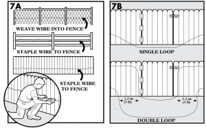
- Chain Link Fence (7A): Weave Boundary Wire through the links or use plastic quick ties.
- Wooden Split Rail or Privacy Fence (7A): Use staples to attach Boundary Wire. Avoid puncturing the insulation of the Boundary Wire.
- Double Loop with an Existing Fence: Run Boundary Wire on top of the fence and return it on the bottom of the fence to get the 1.5 m (5 ft) separation needed.
- Gate (Single Loop) (7B): Bury the Boundary Wire in the ground across the gate opening. Note: The signal is still active across the gate. Your pet cannot pass through an open gate.
- Gate (Double Loop) (7B): Bury both Boundary Wires across the gate opening while keeping them at least 1.5 m (5 feet) apart.
To Cross Hard Surfaces (driveways, sidewalks, etc.)
![]() WARNING:
WARNING:
Follow all safety instructions for your power tools. Be sure to always wear your safety goggles.
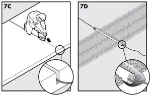
- Concrete Driveway or Sidewalk (7C): Place the Boundary Wire in a convenient expansion joint or create a groove using a circular saw and masonry blade. Place the Boundary Wire in the groove and cover with an appropriate waterproofing compound. For best results, brush away dirt or other debris before patching.
- Gravel or Dirt Driveway (7D): Place the Boundary Wire in a PVC pipe or water hose to protect the Boundary Wire before burying.
STEP 8: Place the Boundary Flags
The Boundary Flags are visual reminders for your pet of where the Warning Zone is located.
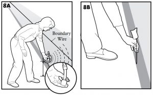
- Hold the Receiver Collar at your pet’s neck height.
- Walk towards the Warning Zone until the Receiver Collar beeps (8A).
- Place a Boundary Flag in the ground (8B).
- Walk back into the Pet Area until the beeping stops.
- Repeat this process around the Warning Zone until it is marked with Boundary Flags every 3 m (10 ft).
Note: If you cannot hear the beep, see the Test Light Instructions in Step 6.
CAUTION: To prevent an unintended stimulation, after the Boundary Flags have been placed, be sure to set the Static Stimulation on the Receiver Collar back to level 1 Tone Only.
STEP 9: Fit the Receiver Collar
Important: The proper fit and placement of your Receiver Collar is important for effective operation. The Contact Points must have direct contact with your pet’s skin on the underside of his neck.
Please read and follow the instructions in this manual. Proper fit of the collar is important. A collar worn for too long or made too tight on the pet’s neck may cause skin damage. Ranging from redness to pressure ulcers; this condition is commonly known as bed sores.
- Avoid leaving the collar on the dog for more than 12 hours per day.
- When possible reposition the collar on the pet’s neck every 1 to 2 hours.
- Check the fit to prevent excessive pressure; follow the instructions in this manual.
- Never connect a lead to the electronic collar; it will cause excessive pressure on the contacts.
- When using a separate collar for a lead, don’t put pressure on the electronic collar.
- Wash the dog’s neck area and the contacts of the collar weekly with a damp cloth.
- Examine the contact area daily for signs of a rash or a sore.
- If a rash or sore is found, discontinue use of the collar until the skin has healed.
- If the condition persists beyond 48 hours, see your veterinarian.
- For additional information on bed sores and pressure necrosis, please visit our website.
These steps will help keep your pet safe and comfortable. Millions of pets are comfortable whilethey wear stainless steel contacts. Some pets are sensitive to contact pressure. You may find after some time that your pet is very tolerant of the collar. If so, you may relax some of these precautions. It is important to continue daily checks of the contact area. If redness or sores are found, discontinue use until the skin has fully healed. You may need to trim the hair in the area of the Contact Points. Never shave the dog’s neck; this may lead to a rash or infection.
To assure a proper fit, please follow these steps:
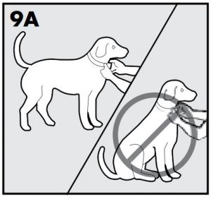
- Turn the Receiver Collar battery to the OFF position.
- Have your pet standing comfortably (9A).
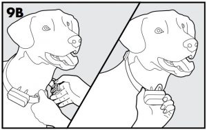
- Place the Receiver Collar on your pet so that the battery module is pointing down. Centre the Contact Points underneath your pet’s neck, touching the skin (9B). CAUTION: You may need to trim the hair in the area of the Contact Probes. Never shave the dog’s neck; this may lead to a rash or infection.
- The Receiver Collar should fit snugly, yet loose enough to allow one finger to fit between a Contact Point and your pet’s neck (9B). Allow your pet to wear the collar for several minutes, then recheck the fit. Check the fit again as your pet becomes more comfortable with the Receiver Collar.
- Once you are satisfied with the fit of the Receiver Collar then you may trim any excess collar strap as follows (9C): a. Mark the desired length of the Receiver Collar with a pen. Allow for growth if your pet is young or grows a thick winter coat.b. Remove the Receiver Collar from your pet and cut off the excess.c. Before placing the Receiver Collar back onto your pet, seal the edge of the cut collar by applying a flame along the frayed edge.
 CAUTION: You may need to trim the hair in the area of the Contact Probes. Never shave the dog’s neck; this may lead to a rash or infection.
 a. Mark the desired length of the Receiver Collar with a pen. Allow for growth if your pet is young or grows a thick winter coat.b. Remove the Receiver Collar from your pet and cut off the excess.c. Before placing the Receiver Collar back onto your pet, seal the edge of the cut collar by applying a flame along the frayed edge.
To Re-Thread the Collar

TRAINING GUIDE
Be Patient With Your Pet
Important: Proper training of your pet is essential to the success of the Little Dog Deluxe In-Ground Fence™ . Read this section completely before beginning to train your pet. Remember that the Little Dog Deluxe In-Ground Fence™ is not a solid barrier.
- Have fun with your pet throughout the training process. Training should be fun, fair, firm and consistent.
- Train for 10 to 15 minutes at a time. Don’t try to do too much too quickly. More-frequent short sessions are better than less frequent longer sessions.
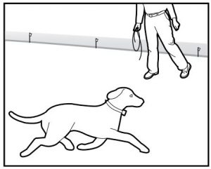
- If your pet shows signs of stress, slow down the training schedule, add additional days of training, or increase the amount of play time with your pet in the Pet Area. Common stress signals include:– Pet pulling on lead toward the house– Ears tucked– Tail down– Body lowered– Nervous / frantic movement or stiffening of pet’s body
- Your pet must be completely comfortable near the Boundary Flags at the end of every training session. Spend at least 5 minutes of “play time” at the completion of each session within 3 m (10 ft) of the Boundary Flags.
- Finish each training session on a positive note with lots of praise and play.
- Remove the Receiver Collar after each training session.
- Be sure to contain your pet by another means during the training period (e.g. pen, tie-out, lead, etc.).
- During training, if you need to take your pet out of the Pet Area, remove the Receiver Collar and either pick your pet up or put him in the car to pass out of the Pet Area.
- Even if you think your pet is responding well to the training, complete the entire training. Reinforcement is important!
PHASE 1: Day 1 – Boundary Awareness
Perform three training sessions per day, each lasting 10 to 15 minutes.
Goal:To have your pet learn that the Boundary Flags and warning beep from the Receiver Collar defines the new Pet Area.
Setup:Program the Static Stimulation Level on the Receiver Collar to Level 1 Tone Only training mode.Put a separate non-metallic collar on your pet’s neck ABOVE the Receiver Collar and attach a lead.
CAUTION: Be sure the extra collar does not put pressure on the Contact Points.
Have tiny pieces of treats that your pet will find desirable available.Have your pet’s favourite play toy available.
Steps:
- Begin by walking your pet on a lead in the Pet Area. Calmly praise and talk to your pet.
- Move toward the Boundary Flags (10A). Keep your mood happy.
- With full control of your pet on a lead, walk to the flags. As your pet enters the Static Stimulation Zone, the Receiver Collar will begin to beep (10B). Allow your pet to stay in the Static Stimulation Zone for up to 2 seconds then gently help him back into the Pet Area (10C). Immediately praise and offer your pet a treat as he enters the Pet Area, even if you have helped with the lead.
- Repeat this process at the same Boundary Flag until your pet resists going into the Static Stimulation Zone.
- Aim to master 3 to 4 Boundary Flags per session. Make this FUN! Praise if your pet quickly retreats or resists going into the Static Stimulation Zone.

PHASE 2: Days 2 thru 4 – Continue Boundary Awareness
Perform three training sessions per day, each lasting 10 to 15 minutes.
Goal:To train your pet to stay in the Pet Area and respect the boundary.
Setup:Program the Static Stimulation Level on the Receiver Collar to Level 2.Put a separate non-metallic collar on your pet’s neck ABOVE the Receiver Collar and attach a lead.
CAUTION: Be sure the extra collar does not put pressure on the Contact Points.
Have tiny pieces of treats available.Have your pet’s favourite play toy available.
Steps:
- Repeat steps 1 thru 5 in Phase One.
- If your pet does not respond to the Static Stimulation, confirm that the Receiver Collar is fitting properly according to Step 9 on page 16.
- If the Receiver Collar is fitted properly and your pet does not respond to the Static Stimulation, increase the Static Stimulation Level by 1. Watch for slight reactions at first such as ears up, head turned, looking at the ground.
- Stay at the same flag until your pet resists going into the Static Stimulation Zone.
PHASE 3: Days 5 thru 8 – Distraction Phase
Perform three training sessions per day, each lasting 10 to 15 minutes.
Goal:To train your pet to stay within the Pet Area with distractions outside of the Pet Area.
Setup:
- Program the Static Stimulation Level on the Receiver Collar to level 2 or higher depending on the reaction results from days 2 thru 4.
- Put a separate non-metallic collar on your pet’s neck ABOVE the Receiver Collar and attach a lead.
CAUTION: Be sure the extra collar does not put pressure on the Contact Points.
- Have tiny pieces of treats available.
- Have your pet’s favourite play toy available.
- Create distractions to tempt your pet to enter the Static Stimulation Zone,such as:
- Have a family member cross from inside the Pet Area to outside of it.
- Throw a ball or treat outside of the Pet Area.
- Have a neighbor walk their pet outside of the Pet Area.
- Gradually increase distraction level.
Never coax or call your pet out of the pet area.Steps:
- With full control of your pet on a lead, have the distraction presented.
- If your pet does not move toward the distraction, praise and offer a treat.
- If your pet does react to the distraction, allow him to go into the Static Stimulation Zone.
- Help your pet back into the Pet Area if he does not turn back after 2 seconds.
- Treat and praise your pet anytime he comes back into the Pet Area with or without help.
- Repeat this process with other distractions. Use other family members during this process.
- If your pet does not respond to the Static Stimulation, confirm that the Receiver Collar is fitting properly according to Step 9 on page 16 .
- If the Receiver Collar is fitted properly and if your pet does not respond to the Static Stimulation, increase the Static Stimulation Level by 1.
PHASE 4: Days 9 thru 14 – Off-lead Supervision
Training sessions should start at 10 to 15 minutes, gradually increasing to over an hour.
Your pet is ready for this step only when he clearly avoids the entire Static Stimulation Zone, regardless of any distractions or temptations. During this step, do not leave your pet unattended.
Goal:To give your pet free run of the Pet Area off the lead.
Setup:Adjust the Receiver Collar to the permanent setting appropriate for your pet.
Steps:
- Enter the Pet Area with your pet wearing the Receiver Collar.
- Walk around the garden and play with your pet, staying within the Pet Area at all times.
- Preoccupy yourself with another task in the garden while watching your pet.
- Should your pet escape, take the Receiver Collar off and lead him back into the Pet Area.
PHASE 5: Days 15 thru 30 – Pet Monitoring
Your pet is ready to run! Check in on your pet at regular intervals.
Note: After you are satisfied your pet’s training is complete, remove every other Boundary Flag every 4 days until all flags are removed. Save Boundary Flags for future use.
PHASE 6: Days 31+ Tone Only Training
Once you have completed training, you may want to switch to the tone only mode. Your pet should now understand the tone and respond quickly as to avoid getting into the Static Stimulation Zone.
Note: You may want to do a refresher course once a month, or at least every other month with your pet by setting the collar back to the tone stimulation mode and following the earlier phases of training. This will help your pet through continual training to be well maintained in the Pet Area.
Taking Your Pet Out of the Pet Area
Important: Remove the Receiver Collar and leave it in the Pet Area.
Once your pet learns the Boundary Zone, he will be reluctant to cross it for walks or car rides.
Option 1: Replace the Receiver Collar with a regular collar. Put your pet in a car that is within the Pet Area and drive him out of the Pet Area.
Option 2: Replace the Receiver Collar with a regular collar and lead. Walk your pet out of the Pet Area while giving a command such as “OK” at a specific place of the Boundary Zone (the end of your driveway, sidewalk, etc.). Always leave the Pet Area with a lead at this place and your pet will associate leaving the Pet Area only on a lead, only at this place, and only with a person. You may initially need to convince your pet to leave the Pet Area with a food treat and lots of praise.
Note: You may also carry your pet out of the Pet Area.
Congratulations! You have now successfullycompleted the training program.
Accessories
To purchase additional accessories for your PetSafe® Little Dog Deluxe In-Ground FenceTM, contact the Customer Care Centre or visit our website at to locate a retailer near you. For a listing of Customer Care Centres in your area visit www.petsafe.com.
Troubleshooting
Additional Information
- Use care when using a string trimmer or when digging near the Boundary Wire to prevent damage.
- The system should only be used with healthy pets who are over 6 months of age. Contact your veterinarian if you have concerns about the medical condition of your pet (medication, pregnant, heart conditions, etc.).
- The Little Dog Deluxe In-Ground Fence™ is for residential use only.
- The Static Stimulation will get your pet’s attention, but will not cause harm. It is designed to startle, not to punish.
- Test the Receiver Collar at least once a month to verify it is functioning properly. Check that it activates at the Boundary Wire. Battery life depends upon how often the Receiver Collar is activated.
- Remove the Receiver Collar from your pet when indoors for the comfort of your pet.
CAUTION: Never leave the Receiver Collar on your pet for more than 12 consecutive hours.
System Test
The system test is used to determine the cause of system problems that have not been addressed elsewhere in this guide. You will need a 3 m (10 ft ) piece of Boundary Wire with 1 cm (3⁄8″) of insulation removed from each end to use as a test loop wire.
Follow the steps below to perform the system test:
- Remove the Receiver Collar from your dog and make sure it is turned on with a good battery installed.
- Unplug the Power Adaptor from the Fence Transmitter Power Jack.
- Set the Boundary Control switch to B.
- Set the Receiver Collar Static Stimulation Level to 5.
- Disconnect the twisted Boundary Wire from the Boundary Wire terminals on the Fence Transmitter by pressing the red release levers on the connector and pulling the wires free.
- Insert the two ends of the test loop wire into the Boundary Wire Terminals on the transmitter.
- Plug the Power Adaptor into Fence Transmitter Power Jack.
- Note the original position of the Boundary Width Control knob and turn the Boundary Width control knob to 10 and then back to 5.
- Place the Test Light Tool Contacts on the Contact Points of the Receiver Collar. While holding the Receiver Collar with the Test Light Tool in place, start outside of the test loop and walk toward the loop. Make a mental note of the distance between you and the wire when the Receiver Collar activates.
- Turn the Boundary Width Control knob to 10 and repeat Step 9. The distance where the Receiver Collar activates should be greater than that of Step 9.
- If more than one Receiver Collar is used on the system, repeat the above test on each collar.
- Interpreting the Results:a. If the Power light or the Loop indicator light are not both lit on the Fence transmitter, or the alarm is on, there is a problem with the transmitter. Contact the Customer Care Centre. (Australia and New Zealand only: Check and replace the Fence Transmitter fuse if necessary. If replacing the fuse does not correct the problem, there is a problem with the transmitter. Contact the Customer Care Centre.)b. If both the Power and Loop indicator lights are on, but the Receiver Collar does not activate on the test loop wire, the Receiver Collar is not working. Contact the Customer Care Centre.c. If both the Power and Loop indicator lights are on and the Receiver Collar is activating at different distances on the test loop wire, the problem is in the containment Boundary Wire .
- If both the Power and Loop indicator lights are on and the Receiver Collar is activating at different distances on the test loop wire, the problem is in the containment Boundary Wire. Perform the Wire Break Location Test.
- When testing is complete, return the Boundary Control Switch and the Boundary Width Control setting to their original position.
- Repeat the Boundary Width testing from Step 6 on Page 13 until you achieve the desired Boundary Width between 3.7 m and 6.1 m (12 ft and 20 ft).
Transmitter Loop Test
The Transmitter Loop Test is a simple test to determine the cause of a “Boundary Wire Broken or Disconnected” alarm indication. You will need a short 3 metre (10 foot) piece of Boundary Wire with 1cm (3⁄8″) of insulation stripped from both ends.
CAUTION: The receiver collar should not be on your dog when the system is tested. Your petmay receive an unintended stimulation.
Verify the transmitter is plugged into the AC power outlet and all Boundary Wire connections at the transmitter are properly connected. If the transmitter Power light is on, the Loop indicator light is off, and the alarm is on, continue with the following steps:
- Remove the twisted wire from the Fence Transmitter Boundary Loop terminals by pushing the red release levers on the connector and pulling the wires free.
- Insert both ends of the 3 m (10 ft) wire loop into the Boundary Loop Terminals and recheck the transmitter Loop indicator light and alarm.a. If the Loop indicator light is green and the alarm is off, there is a problem with the Boundary Wire. Check for visible damage to the wire at the entry into the house. If none is observed, perform the Wire Break Location Test to find and correct the wire break in your Boundary Loop.b. If the Loop indicator light is still off and the alarm is on, there is a problem with the Fence Transmitter.
- Contact the Customer Care Centre for assistance.
Wire Break Location Test
Please follow these steps in determining where you have a break in your Boundary Wire:
- Locate your original splice(s) and verify they have a good, solid connection.
- Check your garden to determine any possible damage to the Boundary Wire (e.g. recent digging, aerating, rodent burrowing, or any other noticeable disturbance in your garden next to the Boundary Wire).
If you still cannot find the break in the Boundary Wire, there are two options for locating it:
Option 1: Contact the Customer Care Centre to purchase a Wire Break Locator that will locate the break in the Boundary Wire.
Option 2: Follow the procedure below:
- Unplug the Fence Transmitter.
- Connect both ends of your twisted Boundary Wire to one Boundary Wire Terminal.
- Measure and cut a Test Wire which is half the length of your total Boundary Wire footage.
- Connect one end of the Test Wire to the other Boundary Wire Terminal.
- Locate the halfway point of your boundary and cut the Boundary Wire.
- Splice the other end of the Test Wire to either side of your Boundary Wire where you cut itin half.
- Plug in the Fence Transmitter and check the Loop Indicator Light. If the Loop Indicator Light is on you can assume the break is in the other half of the Boundary Wire.
- If the Loop Indicator Light did not come on, you may assume there is a break in this portion of the Boundary Wire. However, there is a small chance of having more than one break in your system. Be sure to check both halves of your entire loop.
- Replace the damaged Boundary Wire with new Boundary Wire.
- Reconnect the Boundary Wire to the Fence Transmitter.
- Check the Loop Indicator Light. If the Loop Indicator Light is on, test the system with the Receiver Collar.
Battery Disposal
Separate collection of spent batteries is required in many regions. Check the regulations in your area before discarding spent batteries. At the end of the product life, please contact our Customer Care Center to receive instructions on proper disposal of the unit. Please do not dispose of the unit in household or municipal waste. For a listing of Customer Care Center telephone numbers in your area, visit our website at www.petsafe.com.
![]() Important Recycling AdvicePlease respect the Waste Electrical and Electronic Equipment regulations in your country. This equipment must be recycled. If you no longer require this equipment, do not place it in the normal municipal waste system. Please return it to where it was purchased in order that it can be placed in our recycling system. If this is not possible, please contact the Customer Care Centrefor further information.
Important Recycling AdvicePlease respect the Waste Electrical and Electronic Equipment regulations in your country. This equipment must be recycled. If you no longer require this equipment, do not place it in the normal municipal waste system. Please return it to where it was purchased in order that it can be placed in our recycling system. If this is not possible, please contact the Customer Care Centrefor further information.
Terms of Use and Limitation of Liability
- Terms of UseThe use of this product is subject to your acceptance without modification of the terms, conditions and notices contained with this product. Use of this product implies acceptance of all such terms, conditions, and notices. If you do not wish to accept these terms, conditions, and notices, please return the product, unused, in its original packaging and at your own cost and risk to the relevant Customer Care location together with proof of purchase for a full refund.
- Proper UseProper Use includes, without limitation, reviewing the entire product manual and any specific safety information statements. The specific temperament or size/weight of your pet may not be suitable for this product. If you are unsure whether this product is appropriate for your pet, please consult your veterinarian or certified trainer prior to use. For products used with pets where training is desired, Radio Systems Corporation recommends that these training products are not used if your pet is aggressive and accepts no liability for determining suitability in individual cases.
- No Unlawful or Prohibited UseThis product is designed for use with pets only. This device is not intended to harm, injure, or provoke. Using this product in a way that is not intended could result in violation of Federal, State or local laws.
- Limitation of LiabilityIn no event shall Radio Systems Corporation or any of its associated companies be liable for (i) any direct, indirect, punitive, incidental, special or consequential damage and/or (ii) any loss or damages whatsoever arising out of or connected with the use or misuse of this product. The Purchaser assumes all risks and liability from the use of this product to the fullest extent permissible by law.
- Modification of Terms and ConditionsRadio Systems Corporation reserves the right to change the terms, conditions and notices governing this product from time to time. If such changes have been notified to you prior to your use of this product, they shall be binding on you as if incorporated herein.
Compliance
![]()
Radio Systems Corporation declares under its own responsibility, that the following product is in compliance with the essential requirements under article 3 of the RED (2014/53/EU) and the RoHS 2 Directive (EU) 2015/863. Unauthorised changes or modifications to the equipment that are not approved by Radio Systems Corporation may violate EU RED regulations, could void the user’s authority to operate the equipment, and will void the warranty. Hereby, Radio Systems Corporation, declares that this part is in compliance with the essential requirements and other relevant provisions. The Declaration of Conformity can be found at: www.petsafe.com/customercare/eu_docs.php.
ICThis device complies with Industry Canada license-exempt RSS standard(s). Operation is subject to the following two conditions: (1) this device may not cause interference, and (2) this device must accept any interference, including interference that may cause undesired operation of the device.
ACMAThis device complies with the applicable EMC requirements specified by the ACMA (Australian Communications and Media Authority).
Radio Systems Corporation10427 PetSafe WayKnoxville, TN 37932+1 (865) 777-5404
Radio Systems PetSafe Europe Ltd.2nd Floor, Elgee Building, Market SquareDundalk, Co. Louth, A91 YR9X Ireland+353 (0) 76 892 0427
Radio Systems Australia Pty Ltd.Suite 11001 Australia Fair Office Towers36 Marine ParadeSouthport, QLD 4215, Australia+61 (0) 7 5556 3800
petsafe.comYU400-802-19/4©2020 Radio Systems Corporation
References
[xyz-ips snippet=”download-snippet”]