![]()
![]() Philio TechZ-Wave 3 in 1 Sensor (Door /Window, Illumination, Temperature)
Philio TechZ-Wave 3 in 1 Sensor (Door /Window, Illumination, Temperature)
SKU: PHI_PST02-1C
 |
 |
QuickstartThis is a secure Alarm Sensor for Europe. To run this device please insert fresh 1 * CR123A batteries. Please make sure the internal battery is fully charged add this device to your network execute the following action:
- Has Z-Wave Controller entered inclusion mode?
- Pressing tamper key three times within 1.5 seconds to enter the inclusion mode.
- After add successfully, the device will wake to receive the setting command from Z-Wave Controller for about 20 seconds.
Important safety information
Please read this manual carefully. Failure to follow the recommendations in this manual may be dangerous or may violate the law. The manufacturer, importer, distributor, and seller shall not be liable for any loss or damage resulting from failure to comply with the instructions in this manual or any other material. Use this equipment only for its intended purpose. Follow the disposal instructions. Do not dispose of electronic equipment or batteries in a fire or near open heat sources.
What is Z-Wave?
 Z-Wave is the international wireless protocol for communication in the Smart Home. This device is suited for use in the region mentioned in the Quickstart sect Z-Wave ensures a reliable communication by reconfirming every message (two-way communication) and every mains powered node can act as a repeater for other nodes (meshed network) in case the receiver is not in direct wireless range of the transmitter.This device and every other certified Z-Wave device can be used together with any other certified Z-Wave device regardless of brand and origin as long as both are suited for the same frequency range.If a device supports secure communication it will communicate with other devices secure as long as this device provides the same or a higher level of security. Otherwise, it will automatically turn into a lower level of security to maintain backward compatibility.For more information about Z-Wave technology, devices, white papers, etc. please refer to www.z-wave.info.
Product Description
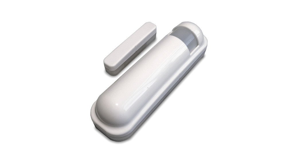
With the 3-in-1 Sensor PST02-1C by Philio, you can not only monitor your door’s and window’s status because the device is equipped with 3 different sensors
- Door/Window Sensor
- Temperature Sensor
- Light Sensor
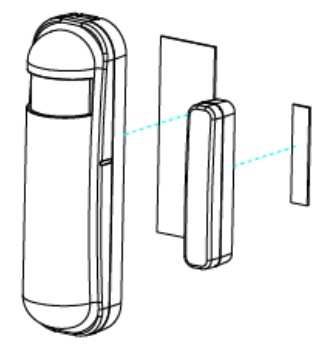
The sensor consists of two parts: a detector and a magnet. The Magnet should be mounted on the door’s/window’s opening part and the detector on the fixedOpening the door/window will remove the magnetic field, trigger the detector and generate an alarm condition, (if the system is armed).The sensor can also be used for automatic light control, one possible scene is to get the illumination lux level from built-in light sensors and send a signal to the Control center to turn the light on once the door will be opened when the room is dark. Every time, when the door/window sensor triggers a status change, it will. http://manual.zwave.eu/backend/make.php?lang=en&sku=PHI_PST02-1C send temperature and brightness value.
Features:
- Contact sensor monitors door and window status (open/closed)
- Measures and reports additional values for temperature and brightness
- Tamper protection
- Can be mounted on every planar surface in a vertical or horizontal position
- Firmware update „Over The Air“ (OTA)
- Power Supply: Batterie (1x CR123A)
- Wireless Technology: Z-Wave Plus
- Dimensions: 28 x 95 x 35 mm
Prepare for Installation / Reset
Please read the user manual before installing the product.In order to include (add) a Z-Wave device to a network, it must be in the factory default state. Please make sure to reset the device into factory default. You can perform an Exclusion operation as described below in the manual. Every Z-Wave controller is able to perform this operation however it is recommended the primary controller of the previous network make sure the very device is excluded properly from this network.
Reset to factory default
This device also allows being reset without any involvement of a Z-Wave controller. This procedure should only be used when the primary controller is in opera
- Pressing the tamper key four times within 1.5 seconds and do not release the tamper key in the 4th pressed, and the LED will light ON.
- After 3 seconds the LED will turn OFF, after that within 2 seconds, release the tamper key. If successful, the LED will light ON one second. Otherwise will flash once.
- IDs are excluded and all settings will reset to factory default.
Safety Warning for Batteries
The product contains batteries. Please remove the batteries when the device is not used. Do not mix batteries of different charging level or different brands.
Installation
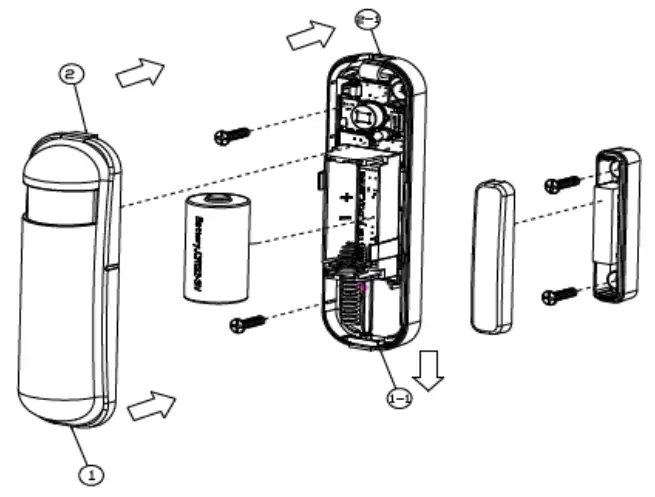
Battery InstallationWhen the device reports a low battery message. The user should replace the battery with the new one. The battery type is CR123A, 3.0V. The way to open the form please follow the below steps.
- Using a tool to press the 1-1 position, to release the cover.
- Hold the front cover and pull back
- Hold the front cover and pull up
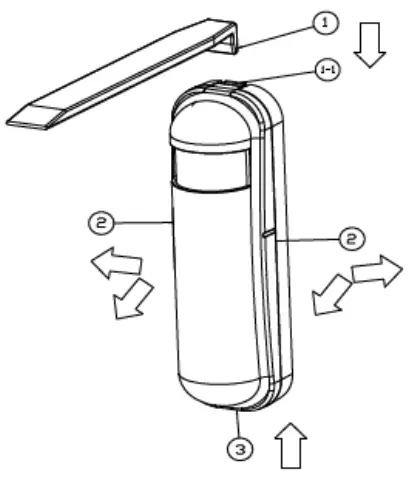
Replace the new battery and install the cover back.
- Put the front cover bottom to 1-1, and press down.
- Push the front cover top to 2-1.
Choosing a Suitable Location
- The recommended mounting height is 160cm
- Don”t let the device facing the window or the sunlight.
- Don”t let the device facing the source of heat. For instance the heater or the air-conditioning.
Installation
- In the first time, add the device into the Z-WaveTM network. First, make sure the primary controller is in the inclusion mode. And then power on the device, ju take out the insulation Mylar in the backside of the device. The device will auto-start the NWI (Network Wide Inclusion) mode. And it should be included in 5 seconds. You will see the LED light ON one second.
- Let the controller associate with the device into the first group, any light switch that intend to be turned on when the device trig please associate with the device into the second group.
- In the accessory pack. There are two type of double-coated tape, one is thicker (hereinafter referred to as A tape) and another is thinner (hereinafter referred as B tape), you can use A tape for the test at the beginning. The right way for A tape installation is stick it to the position below tamper key. The thicker tapewon”t let the tamper key be pressed, so the sensor will enter the test mode, You may test if the installed position is good or not by this way.
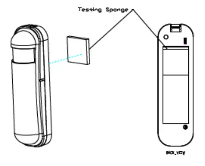
After finish the test and decide to fix, then you can remove tape A, and mounting the sensor by using tape B. The tamper key will be pressed and let the sensor normal mode.
 Inclusion/ExclusionOn factory default, the device does not belong to any Z-Wave network. The device needs to be added to an existing wireless network to communicate with thdevices of this network. This process is called Inclusion.
Devices can also be removed from a network. This process is called Exclusion. Both processes are initiated by the primary controller of the Z-Wave network. Tcontroller is turned into exclusion respective inclusion mode. Inclusion and Exclusion is then performed doing a special manual action right on the device.
Inclusion
- Have Z-Wave Controller entered inclusion mode.
- Pressing tamper key three times within 1.5 seconds to enter the inclusion mode.
- After add successful, the device will wake to receive the setting command from Z-Wave Controller about 20 seconds.
Exclusion
- Have Z-Wave Controller entered exclusion mode.
- Pressing tamper key three times within 1.5 seconds to enter the exclusion mode.
- Node ID has been excluded.
Node Information FrameThe Node Information Frame (NIF) is the business card of a Z-Wave device. It contains information about the device type and the technical capabilities. The inclined exclusion of the device is confirmed by sending out a Node Information Frame. Beside this it may be needed for certain network operations to send out an information Frame. To issue a NIF execute the following action: Press any key once, the device will awake 10 seconds.
Communication to a Sleeping device (Wakeup)This device is battery operated and turned into deep sleep state most of the time to save battery life time. Communication with the device is limited. In order to communicate with the device, a static controller C is needed in the network. This controller will maintain a mailbox for the battery-operated devices and store commands that can not be received during deep sleep state. Without such a controller, communication may become impossible and/or the battery life time is significantly decreased. This device will wakeup regularly and announce the wakeup state by sending out a so called Wakeup Notification. The controller can then empty the mailbox. Therefore, the device needs to be configured with the desired wakeup interval and the node ID of the controller. If the device was included by a static controller will usually perform all necessary configurations. The wakeup interval is a tradeoff between maximal battery lifetime and the desired responses of the device. To wake up the device please perform the following action: Press any key once, the device will awake 10 seconds.
Quick troubleshootingHere are a few hints for network installation if things dont work as expected.
- Make sure a device is in a factory reset state before including. In doubt exclude before include.
- If inclusion still fails, check if both devices use the same frequency.
- Remove all dead devices from associations. Otherwise you will see severe delays.
- Never use sleeping battery devices without a central controller.
- Dont poll FLIRS devices.
- Make sure to have enough mains powered devices to benefit from the meshing
Firmware-Update over the AirThis device is capable of receiving a new firmware ‘over the air. The update function needs to be supported by the central controller. Once the controller starts update process, perform the following action to confirm the firmware update: The device support the Z-Wave firmware update via OTA. Before starting the proplease remove the front cover of the device. Otherwise, the hardware check will be failed. Let the controller into the firmware update mode, and then press thetamper key once to start the update. After finish the firmware download, the LED will start flash in every 0.5 second. At that time, please don”t remove the bat otherwise it will cause the firmware broken, and the device will no function. After the LED stop flash, it is recommended that the user power up the device. CaAfter remove the battery, please wait about 30seconds, and then re-install the battery.
Association – one device controls an other deviceZ-Wave devices control other Z-Wave devices. The relationship between one device controlling another device is called association. In order to control a diffedevice, the controlling device needs to maintain a list of devices that will receive controlling commands. These lists are called association groups and they arerelated to certain events (e.g. button pressed, sensor triggers, …). In case the event happens all devices stored in the respective association group will receivesame wireless command, typically a ‘Basic Set’ Command.
Association Groups:
|
Group Number |
Maximum Nodes |
Description |
| 1 | 8 | Receiving the report message, like triggered event, temperature, illumination, etc. |
| 2 | 8 | Light control, the device will send the “Basic Set” command |
Configuration Parameters
Z-Wave products are supposed to work out of the box after inclusion, however certain configuration can adapt the function better to user needs or unlock furthenhanced features.
IMPORTANT: Controllers may only allow configuring signed values. In order to set values in the range 128 … 255 the value sent in the application shall be the value minus 256. For example: To set a parameter to 200 it may be needed to set a value of 200 minus 256 = minus 56. In the case of a two-byte value, the same applies Values greater than 32768 may be needed to be given as negative values too.
Parameter 2: Basic Set Level
Setting the BASIC command value to turn on the lightSize: 1 Byte, Default Value: 255
| Setting Description | |
| 0 | turn off the light |
| 1 – 100 | the light strength. |
| 254 | turn on the light. |
Parameter 4: Light Threshold
Setting the illumination threshold to turn on the light. When the event-triggered and the environment illumination lower then the threshold, the device will turn light. 0 means turn off illumination detected function. And never turn on the light.Notice: In none test mode, only the value in 1 to 99 will enable the illumination detected function and update the illumination value. Size: 1 Byte, Default Value: 99
| Setting Description | |
| 0 | turn off illumination detected function. |
| 1 – 100 | 1 means darkest. 99 means brightest. 100 means turn off illumination detected function. And always tur light. |
Parameter 5: Operation Mode
Operation mode. Using bit to control. Size: 1 Byte, Default Value: 0
| Setting Description | |
| 1 | Reserve. |
| 2 | 1 means test mode, 0 meazns normal mode. Notice: This bit only effect by the DIP Switch set to “cust mode”, otherwise it decides by DIP Switch setting to Test or Normal Mode |
| 4 | Disable the door/window function. (1:Disable, 0:Enable) |
| 8 | Setting the temperature scale. 0: Fahrenheit, 1:Celsius |
| 16 | Disable the illumination report after the event is triggered. (1:Disable, 0:Enable) |
| 32 | Disable the temperature report after the event is triggered. (1:Disable, 0:Enable) |
| 64 | Reserve. |
| 128 | Disable the back key release into test mode. (1:Disable, 0:Enable) |
Parameter 6: Mult-Sensor Function Switch
Multisensor function switch. Using bit to control. Size: 1 Byte, Default Value: 4
| Setting Description | |
| 1 | Disable magnetic integrate illumination to turn ON the lighting nodes in the association group 2. (1:Disa 0:Enable) |
| 2 | Reserve. |
| 4 | Reserve. |
| 8 | Reserve. |
| 16 | Disable delay 5 seconds to turn off the light, when the door/window closed. (1:Disable, 0:Enable) |
| 32 | Disable auto turn off the light, after door/window opened to turn on the light. (1:Disable, 0:Enable) |
| 64 | Reserve. |
| 128 | Reserve. |
Parameter 7: Customer Function
Customer function switch, using bit control. Size: 1 Byte, Default Value: 4
| Setting Description | |
| 1 | Reserve. |
| 2 | Reserve. |
| 4 | Reserve. |
| 8 | Disable send out BASIC OFF after door closed. (1:Disable, 0:Enable) |
| 16 | Notification Type, 0: Using Notification Report. 1: Using Sensor Binary Report. |
| 32 | Disable Multi CC in auto report. (1:Disable, 0:Enable) |
| 64 | Disable to report battery state when the device triggered. (1:Disable, 0:Enable) |
| 128 | Reserve. |
Parameter 8: PIR Re-Detect Interval Time
In the normal mode, after the PIR motion is detected, setting the re-detect time. 8 seconds per tick, default tick is 3 (24 seconds).Setting the suitable value to preceived the trigger signal too frequently. Also can save the battery energy.Notice: If this value bigger than the configuration setting NO. 9. There is a period alight turned off and the PIR not start detecting. Size: 1 Byte, Default Value: 3
| Setting Description | |
| 1 – 127 | PIR Re-Detect Interval Time |
Parameter 9: Turn Off Light Time
After turn on the lighting, setting the delay time to turn off the lighting when the PIR motion is not detected. 8 seconds per tick, default tick is 4 (32 seconds). never send turn-off light command. Size: 1 Byte, Default Value: 4
| Setting Description | |
| 0 – 127 | Turn Off Light Time |
Parameter 10: Auto Report Battery Time
The interval time for auto report the battery level. 0 means turn off the auto-report battery. The default value is 12. The ticking time can set by the configuration No.20 Size: 1 Byte, Default Value: 12
| Setting Description | |
| 0 – 127 | Auto Report Battery Time |
Parameter 11: Auto Report Door/Window State Time
The interval time for auto-report the door/window state. 0 means turn off auto report door/window state. The default value is 12. The ticking time can be setting by the configuration No.20. Size: 1 Byte, Default Value: 12
| Setting Description | |
| 0 – 127 | Auto Report Door/Window State Time |
Parameter 12: Auto Report Illumination Time
The interval time for auto report the illumination. 0 means turn off auto report illumination.The default value is 12. The tick time can set by the configuratioSize: 1 Byte, Default Value: 12
| Setting Description | |
| 0 – 127 | Auto Report Illumination Time |
Parameter 13: Auto Report Temperature Time
The interval time for auto report the temperature. 0 means turn ofzf auto report temperature.The default value is 12. The tick time can be set by the configuraSize: 1 Byte, Default Value: 12
| Setting Description | |
| 0 – 127 | Auto Report Temperature Time |
Parameter 20: Auto Report Tick Interval
The interval time for auto-report each tick. Setting this configuration will affect configuration No.10, No.11, No.12, and No.13.Caution: Setting to 0 means turn off a report function. Size: 1 Byte, Default Value: 30
| Setting Description | |
| 0 – 255 | Auto Report Tick Interval |
Parameter 21: Temperature Differential Report
The temperature differential to report.0 means turn off this function. The unit is Fahrenheit. Enable this function the device will detect every minutes. And when temperature is over 140 degree Fahrenheit, it will continue report.Enable this functionality will cause some issue please see the detail in the u201cTemperature Reportu201d section. Size: 1 Byte, Default Value: 1
| Setting Description | |
| 0 – 127 | Temperature Differential Report |
Parameter 22: Illumination Differential Report
The illumination differential to report.0 means turn off this function. The unit is a percentage. Enable this function the device will detect every minutes. Enable the functionality will cause some issue please see the detail in the Illumination Report section. Size: 1 Byte, Default Value: 0
| Setting Description | |
| 0 – 99 | Illumination Differential Report |
Technical Data
| Dimensions | 95x28x35 mm |
| Weight | 48 gr |
| Hardware Platform | ZM5202 |
| EAN | 4713698570187 |
| IP Class | IP 20 |
| Battery Type | 1 * CR123A |
| Device Type | Notification Sensor |
| Network Operation | Reporting Sleeping Slave |
| Z-Wave Version | 6.51.02 |
| Certification ID | ZC10-14080018 |
| Z-Wave Product Id | 0x013C.0x0002.0x000E |
| Frequency | Europe – 868,4 Mhz |
| Maximum transmission power | 5 mW |
Supported Command Classes
| AssociationAssociation Group InformationBatterySensor BinaryConfigurationDevice Reset LocallyFirmware Update MdManufacturer Specific | Multi CommandSensor MultilevelNotificationPowerlevelSecurityVersionWake UpZwaveplus Info |
Controlled Command ClassesBasic
Explanation of Z-Wave specific terms
- Controller — is a Z-Wave device with capabilities to manage the network. Controllers are typically Gateways, Remote
- Controls, or battery-operated wall controllers. controllers.
- Slave — is a Z-Wave device without capabilities to manage the network. Slaves can be sensors, actuators and even remote controls.
- Primary Controller — is the central organizer of the network. It must be a controller. There can be only one primary controller in a Z-Wave network.
- Inclusion — is the process of adding new Z-Wave devices into a network.
- Exclusion — is the process of removing Z-Wave devices from the network.
- Association — is a control relationship between a controlling device and a controlled device.
- Wakeup Notification — is a special wireless message issued by a Z-Wave device to announces that is able to communicate.
- Node Information Frame — is a special wireless message issued by a Z-Wave device to announce its capabilities and functions.
 report this ad
(c) 2020 Z-Wave Europe GmbH, Antonstr. 3, 09337 Hohenstein-Ernstthal, Germany, All rights reserved, www.zwave.eu. The template is maintained by Z-Wave Europe GmbH. The product content is maintained by Z-Wave Europe GmbH, Supportteam, [email protected]. Last update of the product data: 2017-02-14 14:31:10
http://manual.zwave.eu/backend/make.php?lang=en&sku=PHI_PST02-1C
References
[xyz-ips snippet=”download-snippet”]