In Wall Roller shutter controllerPAN34
 |
 |
![]()
Introduction
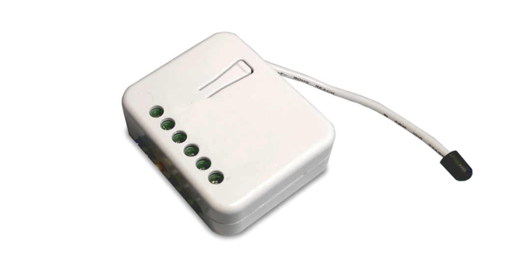
The in-wall Roller Shutter Controller is designed to switch rise/lower roller shutters connected to its terminals using radio waves, controllers, and a push-button directly connected to this Roller Controller.This in-wall Roller Shutter Controller is a Z-Wave Plus™ enabled wireless device fully compatible with any Z-Wave™ enabled networks. This device is a security-enabled ZWave Plus product that uses encrypted Z-Wave Plus messages to communicate to other security-enabled Z-Wave Plus products. Z-Wave™ enabled devices displaying the Z-Wave™ logo can also be used with this device regardless of the manufacturer. This product can be operated in any Z-Wave network with other Z-Wave certified devices from another manufacturer. Within the network, it will act as a repeater regardless of vendor to increase the reliability of the network. The slim design lets the Controller can easily hide itself into the wall box and that will be good for the house decoration. This device must be used in conjunction with a Security Enabled Z-Wave controller in order to fully utilize all functions. Its functionality and supported command classes are identical when included as a secure and non-secure device. The new smart relay calibration technology can reduce the inrush current caused by the load and let the module work perfectly with many kinds of Roller Shutter. This in-wall Roller Shutter Controller is able to detect the position of the Shutter by using the patterned power measuring method, so it can be remote controlled not only fully up or down, but also can be adjusted to ex. 30% or 50%. And when manually controlled by a push button, the controller also can memorize the position and send the new shutter position to its controller (ex. IP-Gateway).
Safety Precautions and Installation
- Avoid installing the unit in storming or raining weather.
- Be sure to isolate or switch off power source before installing or maintenance.
- To ensure that the power supply circuit is protected by a 16A circuit breaker or suitable equivalent fuse.
IMPORTANT
- Installation must be performed by skilled technicians who are informed about the standards and technical requirements of the appliance and its proper installation.
- Check your local codes as they apply to your situation. If the house wiring is of aluminum, consult with an electrician about proper wiring methods.
- Before proceeding with the installation, TURN OFF THE POWER TO THE LIGHTING CIRCUIT AT THE CIRCUIT BREAKER OR FUSE BOX TO AVOID ELECTRICAL SHOCK.
Specification
| Operating Voltage | 100 -240VAC 50-60Hz |
| Maximum Load | Resistive load 5A max. |
| Range | Minimum 40 m indoor 100m outdoor line of sight |
| Operating Temperature | 0°C – 40°C |
| Humidity | Up to 85% max. |
| Storage Temperature | -20°C to 60°C |
| Location | Indoor use only |
| Frequency Range | 868.40MHz; 869.85MHz (EU)908.40MHz; 916.00MHz (USA/Canada)920.90 MHz, 921.70 MHz, 923.10 MHz (Taiwan) |
| RF Maximum Power | +10dBm (Peak), -10dBm (Average) |
| Communication Protocol | Z-Wave™ |
| OTA | Yes |
| FCC ID | RHHPAN34 |
| Dimensions | 47.5 x 39 x16 mm |
| Wire | 0.75mm2, 18AWG |
Specifications are subject to change and improvement without notice.
Troubleshooting
| Symptom | Cause of Failure | Recommendation |
| The PAN34 not working and the LED off | 1. The PAN34 is not connected to the Main power2. The PAN34 breakdown | 1. Check power connections2. Don’t open up the PAN34 and send it for repair. |
| The shutter move direction is reverse | Wrong connection of NC and NO to the motor | Swap the NC NO connection |
| PAN34 LED light work fine But can not control | 1.No association setting2. Same frequency interference3. S1 or S2 are both pressed in Two Push Button switch type, PAN34 would not accept RF command. | 1. Carry out the association2. Wait for a while to re-try3. Release S1 and S2 |
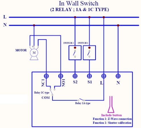
Fig 1. Assembling Installation and operation
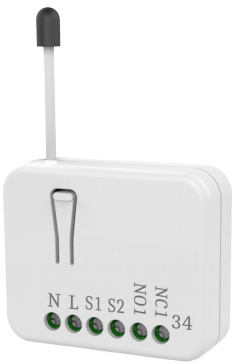
- Put the in-wall PAN34 into a wall box and connect the AC power wire L, N to PAN34 connector L, N.
- Connect the wall switch to the PAN34 as Fig1
- To manually switch up and down of the shutter, simply press the external switch S1 or S2. The detail is described in 7-5.
- PAN34 built-in meter function and can read the Watt, KWh, V(Voltage), I(Current), PF (Power Factor) of the load by using Z-Wave command class, user can set a threshold current to get the warning caused by abnormal operation
- PAN34 have an overload protection function and can help to prevent short circuit
 DANGERDanger of electrocution!
All works on the device may be performed only by a qualified and licensed electrician. Observe national regulations.Any works introducing changes into the configuration must be always performed with disconnected voltage. Choosing a Suitable Location
- Do not locate the Module facing direct sunlight, humid or dusty place.
- The suitable ambient temperature for the Module is 0°C~40°C.
- Do not locate the Module where exists combustible substances or any source of heat, e.g. fires, radiators, boiler, etc.
- After putting it into use, the body of the Module will become a little bit hot of which phenomenon is normal.
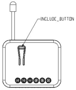
Adding to Z-WaveTM NetworkIn the front casing, there is an included button with an LED indicator below which is used to carry out inclusion, exclusion, reset.The table below lists an operation summary of basic Z-Wave functions. Please refer to the instructions for your Z-Wave Certificated Primary Controller to access the Setup function, and to include/exclude/reset devices.
| Function | Description | LED Indication |
| No node ID | The Z-Wave Controller does not allocate a node ID to the PAN34. | LED 2-second on, 2-second off |
| Add(Classic Inclusion) | 1. Put your Z-Wave controller into inclusion mode by following the instructions provided by the controller manufacturer. | One press one flash LED |
| 2. Pressing the Include button three times within 2 seconds will enter inclusion mode. | ||
| SmartStart | 1. The product has a DSK string. Key in the first five digits to initiate the SmartStart process, or scan OR code.Ex: DSK: 18112-24021- 48001- | |
| 62259-57092-27453-08187-474082.SmartStart enabled products can be added into a Z-Wave network by scanning the Z-Wave” OR Code on the product, with acontroller providing SmartStart inclusion. No further action is required and the SmartStart product will be added automatically to the closest network within 10 minutes of being switched on.Notice:The OR Code can be found on the device PAN34 or in the box. | ||
| Remove | 1. Put your Z-Wave controller into | One press one flash LED |
| (Exclusion) | exclusion mode by following the instructions provided by the controller manufacturer. | |
| 2. Pressing Include button threetimes within 2 seconds will enter exclusion mode. | ||
| Node ID has been excluded. | LED 0.5s On, 0.5s Off (Enter auto inclusion) | |
| Reset | I . Pressing the Include button three timeswithin 2 seconds will enter inclusion mode. | Use this procedure only in the event that the primary controller is lost orotherwise inoperable. |
| 2. Within 1 second, press the Include button again for 5 seconds. | ||
| 3.IDs are excluded. | LED 0.5s On, 0.5s Off (Enter auto inclusion) | |
LED IndicationThere is a LED for identifying functions in the front case. PAN34 support the indicator ID 0x50 (Identify) and Properties ID 0x03, 0x04 and 0x05.To distinguish what mode the PAN34 is in, view from the LED for identification.
| State Type | LED Indication |
| Motor | No matter up or down, close or open, Led will flash every second |
| activate | while Motor activates.When Si or S2 is close to L, the LED will flash even when the motor stop by itself, this is to let the user know the Si or S2 is still closed and has not been released yet. |
| No node ID | Under normal operation, when the PAN34 has not been allocated a node ID, the LED flashes on and off alternately at 2-second intervals. By pressing Si S2 or Include button, it will stop flashing temporarily. |
| Learning | When PAN34 is in learning mode, LED flashes on and off alternately and repeatedly at 0.5-second intervals. |
| Overload | When an overload state occurs, the PAN34 is disabled, and LED flashes on and off alternately at 0.2-second intervals. PAN34 will send alarm type=8 alarm Level=OxFF to Group, Overload state can be cleared by disconnect and reconnect the PAN34 to the main power |
Moving Range Calibration
- It is important to carry out a shutter calibration process before you control the shutter to move. Press inclusion button over 3 seconds and release before the 6th second, the roller shutter controller will start the shutter calibration process. The process is composed of three continue stages. The shutter move to the TOP in the first stage, and move to the BOTTOM in second stage, and move to the TOP again in the third stage. Then PAN34 will know the total range from the BOTTOM to the TOP.
- During the shutter calibration process, any emergencies happen you can press and release the include button to stop the process.
- If the user found the direction is reversed, this may cause by the wrong connection of NC and NO to the motor, please exchange NC and NO connection and execute the calibration process again.
- For a safe issues, please select the motor which can stop by itself when going to the bottom end or top end.
Programming
- Basic Command ClassThe PAN34 will respond to BASIC and BINARY commands that are part of the Z-Wave system.
1.1 BASIC_GETWhen PAN34 receives Basic Get-Command, it will send Basic Report Command to report the position of the shutter. When the report value is 0x00, that mean the shutter is at the Bottom, if the reported value is 0x63 that means the shutter is at the Top, any other value between 0x01~0x62 imply Shutter at the position between top and bottom.
| Basic Get-Command: [Command Class Basic, Basic Get] |
| Basic Report Command:[Command Class Basic, Basic Report, Value = 0x00 (BOTTOM)][Command Class Basic, Basic Report, Value = 0x01~0x62 (Between BOT- |
| TOM and TOP)][Command Class Basic, Basic Report, Value = 0x63 (TOP)] |
1-2 BASIC_SETPAN34 can accept Basic Set Command which value is either (0x00) Bottom orTop (0x63) or (0x01-0x62) the position between TOP and Bottom. Other value (0x64-0xFE) is not acceptable.
| [Command Class Basic, Basic Set, Value = 0x63] control the shutter to the top (0x63) |
| [Command Class Basic, Basic Set, Value = 0x00(0)] control the shutter to the bottom(0x00) |
| [Command Class Basic, Basic Set, Value = 0xFF] control the shutter to the most recent (non-zero) level. |
| [Command Class Basic, Basic Set, Value = 0x01-0x62] control the shutterto the position between bottom and top |
2. Multilevel Switch Command Class (Version 3):2-1 MULTILEVEL SWITCH SET:PAN34 can accept Multilevel Switch Set Command which value is either (0x00) Bottom or Top (0x63) or (0x01-0x62) the position between TOP and Bottom.Another value (0x64-0xFE) is not acceptable.
| [Command Class Multilevel Switch, Multilevel Switch Set, Value = 0x63] control the shutter to the top (0x63) |
| [Command Class Multilevel Switch, Multilevel Switch Set, Value = 0x00(0)] control the shutter to the bottom(0x00) |
| [Command Class Multilevel Switch, Multilevel Switch Set, Value = 0xFF(255)] control the shutter to the most recent (non-zero) level. |
| [Command Class Multilevel Switch, Multilevel Switch Set, Value = 0x010x62]
Control the shutter to the position between Bottom and Top. |
2-2 MULTILEVEL SWITCHES GET:When PAN34 receive Multilevel Switch Get-Command, it will send Multilevel SwitchReport Command to report the position of the shutter. When the reported value is 0x00, that means the shutter is at the Bottom, if the reported value is 0x63 that means the shutter is at the top, any other value between 0x01~0x62 imply shutter at the position between top and bottom.
| Switch Multilevel Get-Command:[Command Class Multilevel Switch, Multilevel Switch Get] |
| Multilevel Switch Report Command:[Command Class Multilevel Switch, Multilevel Switch Report,Value = 0x00(BOTTOM)][Command Class Multilevel Switch, Multilevel Switch Report,Value = 0x01~0x62(Between BOTTOM and TOP)] |
| [Command Class Multilevel Switch, Multilevel Switch Report,Value = 0x63 (TOP)] |
2-3 MULTILEVEL SWITCH START LEVEL CHANGE: This is the command which user can move the shutter up to the top or down to the bottom.
| [Command Class Multilevel Switch, Multilevel Switch Start Level Change,Up/Down Value] |
2-3.1 Up/Down Bit:If Up/Down Bit=0x00 Shutter move upIf Up/Down Bit=0x01 Shutter move downIf Up/Down Bit=0x03 no move
| [Command Class Multilevel Switch, Multilevel Switch Start Level Change,Up/Down=0x00] control the shutter to the top (0x63) |
| [Command Class Multilevel Switch, Multilevel Switch Start Level Change,Up/Down=0x01] control the shutter to the bottom (0x00) |
| [Command Class Multilevel Switch, Multilevel Switch Start Level Change,Up/Down=0x03] Don’t move the shutter or stop the moving shutter |
ATT.
- Ignore Start Level、Start Level、Dimming Duration、Inc/Dec、Step size can not be used.
- PAN34 can not control the speed of the motor.
- It may have some distance error caused by motor start-up time.
- If the user found the error becomes significant, you may using S1 or S2 to move the shutter to the end or remote move the shutter to 0% and 100%, and that will automatically calibrate this error.
2-3.4 MULTILEVEL SWITCH STOP LEVEL CHANGE:When receiving Multilevel Switch Stop Level change Command PAN34 will stop the motor.Z-Wave’s Groups introduction (Maximum 5 nodes) There is only one group called Lifeline,there is only 5 nodes for Group1 which support MULTILEVEL_SWITCH_REPORT、METER_REPORT_COMMAND_V3、NOTIFICATION_REPORT and DEVICE_RESET_LOCALLY_NOTIFICATION. 3-1 Device reset locally notification:When PAN34 is reset manually, it will send a DEVICE_RESET_LOCALLY_ NOTIFICATION to the nodes of group 1.
3-2 Report the shutter position :Every time when the user presses S1 or S2 and lets the shutter move, PAN34 will report the position status to the controller, and during the moving process when change over 10% PAN34 will send Multilevel Switch Report to Group 1 as well.Multilevel Switch Report:Ex. Report position at 30% [Command Class Multilevel Switch,Multilevel Switch Report,Value = 30(%)]
3-3 Meter Command Class:
The Switch will report it’s (1) instant Power Consumption (Watt) or (2) accumulated power consumption(KWH) or (3) AC load Voltage (V) or (4) AC load current ( I ) (5) load power factor (PF) to Z-Wave Controller after receiving the Meter Get-Command from Z-Wave Controller.When the power consumption of load varies over 5%, it will send Meter reports to the nodes of the Group as well
3-3.1 Instant Power Consumption (Watt) of SwitchWhen receiving Meter Get-Command, it will report Meter Report Command to the node asked.
| Meter Get Command: [Command Class Meter, Meter Get, Scale=0x02(W)] |
| Meter Report Command:[Command Class Meter,Meter Report,Rate Type = 0x01,MeterType =0x01,Precision = 1,Scale = 0x02,Size = 4,Meter Value(W) ] |
Example:Meter Value 1 = 0x00 (W)Meter Value 2 = 0x00 (W)Meter Value 3 = 0x03 (W)Meter Value 4 = 0xEA (W)Meter(W) = Meter Value 3 *256 + Meter Value 4 = 100.2W
3-3.2 Accumulated Power Consumption (KW/h)When receiving Meter Get Command, it will report Meter Report Command to the node asked.
| Meter Get Command: [Command Class Meter, Meter Get, Scale = 0x00(KW/h)] |
| Meter Report Command:[Command Class Meter,Meter Report,Rate Type = 0x01, MeterType=0x01, Precision = 2,Scale = 0x00,Size = 4,Meter Value (KWh)] |
Example:Scale = 0x00 (KWh)Precision = 2Size = 4 Bytes (KW/h)Meter Value 1 = 0x00(KWh)Meter Value 2 = 0x01(KWh)Meter Value 3 = 0x38(KWh)Meter Value 4 = 0xA3(KWh)
Accumulated power consumption (KW/h) = (Meter Value 2*65536) + (Meter Value 3*256) + (Meter Value 4) = 800.35 (KW/h)
3-3.3 AC load Voltage (V)When receiving Meter Get-Command, it will report Meter Report Command to the node asked.
| Meter Get Command: [Command Class Meter, Meter Get, Scale=0x04(V)] |
| Meter Report Command:[Command Class Meter,Meter Report,Rate Type = 0x01,MeterType =0x01,Precision = 1,Scale = 0x04,Size = 2, Meter Value(V)] |
Example:Scale = 0x04 (V)Precision = 1Size = 2 (2 Bytes of V)Meter Value 1 = 0x09(V)Meter Value 2 = 0x01(V)AC load Voltage = (Meter Value 1*256) +(Meter Value 2)= 230.5 (V)
3-3.4 AC load current ( I )When receiving Meter Get Command, it will report Meter Report Command to the node asked.
| Meter Get Command: [Command Class Meter, Meter Get, Scale=0x05(I)] |
| Meter Report Command:[Command Class Meter,Meter Report,Rate Type = 0x01,MeterType= 0x01,Precision = 2,Scale = 0x05,Size = 2,Meter Value(I)] |
Example:Scale = 0x05 (I)Precision = 2Size = 2 (2 Bytes of I)Meter Value 1 = 0x01(I)Meter Value 2 = 0x21(I)AC load current = (Meter Value 1*256) +(Meter Value 2)= 2.89 (A)
3-3.5 load power factor (PF)When receiving Meter Get-Command, it will report Meter Report Command to the node asked.
| Meter Get-Command: [Command Class Meter, Meter Get, Scale=0x06(PF)] |
| Meter Report Command:[Command Class Meter,Meter Report,Rate Type = 0x01,MeterType=0x01, Precision = 2,Scale = 0x06,Size = 1 Bytes,Meter Value(PF)] |
Example:Scale = 0x06 (PF)Precision = 2Size = 1 (1 Byte of PF)Meter Value 1 = 0x63(PF) (It means that the load power factor is 0.99)
3-3.6 Reset Accumulated Power Consumption (KWh)Whenever a re-start counting the accumulated power consumption is needed, you can use Meter Reset Command to clear it.
Meter Reset Command:[Command Class Meter, Meter Reset]
4. Notification Report Command:When PAN34 detect Overload, it will send Notification Report to Group1, Notification _Type = 0x08, Notification State=0x08. When it receive Notification Get command with Notification Type = 0x08 and the PAN34 not in overload status, it will send Notification Report, Alarm Type = 0x08, Notification State=0x00.When PAN34 detects an overloaded power, it will send a Notification Report to Group1.
| Command Class Notification, Notification Report, Notification Type = 0x08,Notification State = 0x08 (Overload)] |
| [Command Class Notification, Notification Report, Notification Type = 0x08,Notification State = 0x00 (Normal)] |
When in Two Push Button switch type, S1 or S2 are closed and not released to open, and PAN34 receive any control moving command from Z-Wave RF.
5. Z-Wave’s Configuration
| Configuration Parameter | Function | Size (Byte) | Value | Unit | Default | Description |
| 1 | WattMeter Report Period | 2 | 0 – Ox7FFF | 5s | 720 | O:Disable auto Report 1-0x7FFF: 5s -45 hour |
| 2 | External switch mode | 1 | 1-2 | 2 | 1: One Push button 2:Two Push button | |
| 3 | Total | 2 | 0-6000 | 0.1Second | 0 | 0: The time depends on Moving Range Calibration |
| moving time of curtain | 1 | 1-6000: 0.1s-600s | ||||
| 4 | Watt threshold | 1 | 1-5 | Watt | 1 | The threshold is a judgment for motor running or not |
| 5 | Watt differential | 1 | 0-1 | 1 | 0: It will not report Watt when changing over 5%1: It will report wattvalue when thethe differential is over 5% | |
| 6 | Timer offset for motor start running | 2 | 0-255 | 0.01second | 50 | 0-255: Os – 2.55s 50 = 0.5s |
5-1 Watt Meter Report Period:If the setting is configured for 1hour (set value =720), the PAN34 will report its instant power consumption every 1 hour to the node of Group 1. The maximum interval to report its instant power consumption is 45 hours (5s*32767/3600=45hr). Default value is 1 hour. If the setting value is 0, the auto report function of meter Watt will be disabled.5-2 External switch mode
5-2-1 One Push Button:When the configuration setting is One Push Button, only S1 input will be valid. The control moving commands can be accepted in this switch mode while the shutter is moving. In this switch mode, the inclusion/exclusion/reset function can also be fulfilled by pressing S1 just like the operation of the include button.When S1 is short pressed, the shutter will move up toward TOP(0x63). While in this moving S1 is short pressed again, the shutter will stop moving. A third short pressing of S1 will move the shutter down toward BOTTOM(0x00). While in this moving S1 is short pressed again, the shutter will stop moving. And so on… Inverting direction and stopping.
5-2-2 Two Push Button: (The default setting is Two Push Button (2))If this setting is configured as Two Push Button, S1 and S2 input will be valid, but will not accept pressing S1and S2 at the same time. In this switch mode, the inclusion/exclusion/reset function can also be fulfilled by pressing S1 or S2 just like the operation of the include button.When S1 is pressed and hold for more than 1.5 seconds, the shutter will move up toward TOP(0x63), and the shutter will stop moving when S1 is released.When S2 is pressed and hold for more than 1.5 seconds, the shutter will move down toward BOTTOM(0x00), and the shutter will stop moving when S2 is released.When S1 is short pressed, the shutter will move up toward TOP(0x63). While in this moving short pressed S1 again, the shutter just keeps moving up toward TOP(0x63). The easy way to stop this moving is by short pressing S2. When S2 is short pressed, the shutter will move down toward BOTTOM(0x00). While in this moving short pressed S2 again, the shutter just keeps moving down toward BOTTOM(0x00). The easy way to stop this moving is by short pressing S1.
When in Two Push Button switch mode, S1 or S2 are pressed and not released, and PAN34 receives any control moving command from Z-Wave RF (Ex.BASIC_SET、BINARY_SWITCH_SET、MULTILEVEL_SWITCH_SET、MULTILE VEL_SWITCH_START_LEVEL_CHANGE or LTILEVEL_SWITCH_STOP_LEVEL_CHANGE), PAN34 won’t do any change in position.
ATT. : To avoid misunderstanding that the RF command does not work, it is recommended to check the status of S1 and S2.
5-3 Total moving time of curtain:This away for setting the total moving time of the curtain manually. You can count the time when the shutter moves from BOTTOM to TOP by long-pressing S1 or S2. But if the time is set as 0, the total moving time of the shutter will be the value set by Moving Range Calibration which is describing in Page 3. The default value is 0.
5-4 Watt threshold:The threshold is for PAN34 judging if the motor is running or not. The default value is 1 watt.5-5 Watt differential:Whenever the watt value varies over 5%, PAN34 will send the meter report to group 1 nodes. The default value is 1 (5%).5-6 Timer offset for motor start running:This parameter is an offset to count for starting time of the motor. It will improve the inaccurate when moving to the middle position. The default value is 50.
6. Command ClassesThe Switch supports Command Classes including…
| Command Class |
Version |
Required Security Class |
| Z-Wave Plus Info | 2 | None |
| Security 0 | 1 | None |
| Security 2 | 1 | None |
| Supervision | 1 | None |
| Transport Service | 2 | None |
| Association | 2 | Highest granted Security Class |
| Association Group Information | 3 | Highest granted Security Class |
| Basic | 2 | Highest granted Security Class |
| Configuration | 4 | Highest granted Security Class |
| Device Reset Locally | 1 | Highest granted Security Class |
| Firmware Update Meta Data | 5 | Highest granted Security Class |
| Manufacturer Specific | 2 | Highest granted Security Class |
| Window Covering | 1 | Highest granted Security Class |
| Power level | 1 | Highest granted Security Class |
| Multilevel Switch | 4 | Highest granted Security Class |
| Meter | 3 | Highest granted Security Class |
| Notification | 8 | Highest granted Security Class |
| Indicator | 3 | Highest granted Security Class |
| Multi-Channel Association | 3 | Highest granted Security Class |
| Version | 3 | Highest granted Security Class |
Disposal
 This marking indicates that this product should not be disposed of with other household wastes throughout the EU. To prevent possible harm to the environment or human health from uncontrolled waste disposal, recycle it responsibly to promote the sustainable reuse of material resources. To return your used device, please use the return and collection systems or contact the retailer where the product was purchased. They can take this product for environmentally safe recycling.
Philio Technology Corporation8F., No.653-2, Zhongzheng Rd., Xinzhuang Dist., New Taipei City 24257, Taiwan(R.O.C)www.philio-tech.com
FCC Interference StatementThis equipment has been tested and found to comply with the limits for Class B digital devices, pursuant to Part 15 of the FCC Rules. These limits are designed to provide reasonable protection against harmful interference in a residential installation. This equipment generates, uses, and can radiate radio frequency energy and, if not installed and used in accordance with the instructions, may cause harmful interference to radio communications. However, there is no guarantee that interference will not occur in a particular installation. If this equipment does cause harmful interference to radio or television reception, which can be determined by turning the equipment off and on, the user is encouraged to try to correct the interference by one of the following measures:
- Reorient or relocate the receiving antenna.
- Increase the separation between the equipment and receiver.
- Connect the equipment into an outlet on a circuit different from that to which the receiver is connected.
- Consult the dealer or an experienced radio/TV technician for help.
This device complies with Part 15 of the FCC Rules. Operation is subject to the following two conditions:
(1) This device may not cause harmful interference, and(2) This device must accept any interference received, including interference that may cause undesired operation.FCC Caution: Any changes or modifications not expressly approved by the party responsible for compliance could void the user’s authority to operate this equipment.This transmitter must not be co-located or operating in conjunction with any other antenna or transmitter.
References
[xyz-ips snippet=”download-snippet”]