![]() Philio TechSmart energy plug in switchSKU: PHIEPAN16-106-10-2020 15:47
Philio TechSmart energy plug in switchSKU: PHIEPAN16-106-10-2020 15:47![]()
Quickstart
This is a secure On/Off Power Switch for Europe. To run this device please connect it to your mains power supply. 1. Put your Z-Wave controller into inclusion mode by following the instructions provided by the controller manufacturer. 2. Pressing the On/Off button three times within 2 seconds will enter inclusion mode.
Important safety information
Please read this manual carefully. Failure to follow the recommendations in this manual may be dangerous or may violate the law. The manufacturer, importer, distributor, and seller shall not be liable for any loss or damage resulting from failure to comply with the instructions in this manual or any other material. Use this equipment only for its intended purpose. Follow the disposal instructions. Do not dispose of electronic equipment or batteries in a fire or near open heat sources.
What is Z-Wave?
Z-Wave is the international wireless protocol for communication in the Smart Home. This device is suited for use in the region mentioned in the Quickstart section.Z-Wave ensures reliable communication by reconfirming every message (two-way communication) and every mains powered node can act as a repeater for other nodes (meshed network) in case the receiver is not in direct wireless range of the transmitter.This device and every other certified Z-Wave device can be used together with any other certified Z-Wave device regardless of brand and origin as long as both are suited for the same frequency range.If a device supports secure communication it will communicate with other devices secure as long as this device provides the same or a higher level of security. Otherwise, it will automatically turn into a lower level of security to maintain backward compatibility.For more information about Z-Wave technology, devices, white papers, etc. please refer to www.z-wave.info.
 Product Description
 Product Description
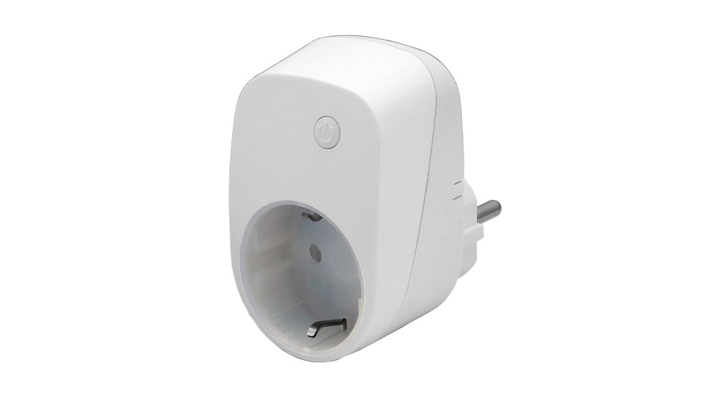
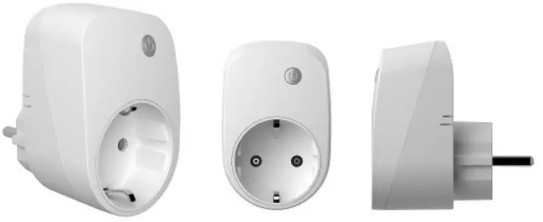
This plug-in ON/OFF switch PAN16 is a security-enabled Z-Wave Plus product, based on Z-Wave Plus technology. The device will enable security mode automatically if the controller supports security mode, too. Z-Wave PlusTM enabled devices displaying the Z-Wave PlusTM logo can also be used with it regardless of the manufacturer, and can also be used in other manufacturer’s Z-WaveTM enabled networks. Remote On/Off control of the connected load is possible with other manufacturer’s wireless Controllers. Each switch is designed to act as a repeater. Repeaters will re-transmit the RF signal to ensure that the signal is received by its intended destination by routing the signal around obstacles and radio dead spots. Because PAN16 supports Security Command Class, it can learn with a Securedenabled Z-Wave controller to fully utilize the device. Its functionality and supported command classes is identical when included as a secure and non-secure device. This plug-in ON/OFF switch is able to detect instance wattage (3000W/230VAC) (13Ampere) and overload current (14.5A with resistive load) of connected lights or appliances. When detecting overload state, the Switch will be disabled and its On/Off button will be lockout of which LED will flash quickly. However, unplug and reconnect the switch will reset its overload condition to normal status.Adding to Z-WaveTM NetworkIn the front casing, there is an On/Off button with an LED indicator which is used to toggle switch on and off or carryout inclusion, exclusion, reset, or association.When first power is applied, its LED flashes on and off alternately and repeatedly at 0.5-second intervals. It implies that it has not been assigned a node ID and start auto inclusion.Auto InclusionThe function of auto inclusion will be executed as long as the switch does not have Node ID and just plug the switch into a wall outlet. Note: Auto inclusion timeout is 2 minutes during which the node information of explorer frame will be emitted once several seconds. Unlike “inclusion†function as shown in the table below, the execution f to inclusion is free from pressing the On/Off button on the Switch.http://manual.zwave.eu/backend/make.php?lang=en&sku=PHIEPAN16-1
Prepare for Installation / Reset
Please read the user manual before installing the product.In order to include (add) a Z-Wave device to a network, it must be in the factory default state. Please make sure to reset the device into factory default. You can doby performing an Exclusion operation as described below in the manual. Every Z-Wave controller is able to perform this operation however it is recommended to the primary controller of the previous network to make sure the very device is excluded properly from this network.Reset to factory defaultThis device also allows being reset without any involvement of a Z-Wave controller. This procedure should only be used when the primary controller is inoperable
- Pressing the On/Off button three times within 2 seconds will enter inclusion mode.
- Within 1 second, press the On/Off button again for 5 seconds.
- IDs are excluded.
Safety Warning for Mains Powered Devices
ATTENTION: only authorized technicians under consideration of the country-specific installation guidelines/norms may do works with mains power. Prior to theassembly of the product, the voltage network has to be switched off and ensured against re-switching.
Installation
- Plug this On/Off Switch into a wall outlet near the load to be controlled.
- Plug the load into the Switch. Make sure the load to be controlled cannot exceed 13A.
- Press the button or switch on the load to the ON position.
- To manually turn ON the Switch, press and release the On/Off button. The LED will turn ON, and the load plugged into the Switch will also turn ON.
- To manually turn OFF the Switch, simply press and release the On/Off button. The LED will turn OFF and the load plugged into the Switch will also turn OFF.
Inclusion/Exclusion
On factory default, the device does not belong to any Z-Wave network. The device needs to be added to an existing wireless network to communicate with the devices of this network. This process is called Inclusion.Devices can also be removed from a network. This process is called Exclusion. Both processes are initiated by the primary controller of the Z-Wave network. The controller is turned into exclusion respective inclusion mode. Inclusion and Exclusion are then performed doing a special manual action right on the device.InclusionPressing the On/Off button three times within 2 seconds will enter inclusion mode.ExclusionPressing the On/Off button three times within 2 seconds will enter exclusion mode.
Product Usage
- Do not locate the Switch facing direct sunlight, humid or dusty place.
- The suitable ambient temperature for the Switch is 0°C~40°C.
- Do not locate the Switch where exists combustible substances or any source of heat, e.g. fires, radiators, boiler, etc.
- After putting it into use, the body of Switch will become a little bit hot of which phenomenon is normal.
Quick troubleshooting
Here are a few hints for network installation if things don’t work as expected.
- Make sure a device is in a factory reset state before including it. In doubt exclude before include.
- If inclusion still fails, check if both devices use the same frequency.
- Remove all dead devices from associations. Otherwise, you will see severe delays.
- Never use sleeping battery devices without a central controller.
- Don’t poll FLIRS devices.
- Make sure to have enough mains powered devices to benefit from the meshing
Association – one device controls another device
Z-Wave devices control other Z-Wave devices. The relationship between one device controlling another device is called association. In order to control a different device, the controlling device needs to maintain a list of devices that will receive controlling commands. These lists are called association groups and they are all related to certain events (e.g. button pressed, sensor triggers, …). In case the event happens all devices stored in the respective association group will receive the same wireless command, typically a ‘Basic Set’ Command.
Association Groups:
| Group Number | Group Number | Description |
| 1 | 1 | Z-Wave Plus Lifeline |
Configuration Parameters
Z-Wave products are supposed to work out of the box after inclusion, however, certain configuration can adapt the function better to user needs or unlock further enhanced features.IMPORTANT: Controllers may only allow configuring signed values. In order to set values in the range 128 … 255 the value sent in the application shall be the disvalue minus 256. For example: To set a parameter to 200 it may be needed to set a value of 200 minus 256 = minus 56. In the case of a two-byte value, the same logic applies: Values greater than 32768 may be needed to be given as negative values too.Parameter 1: Watt Meter Report PeriodIf the setting is configured for 1hour (set value =720), the PAN16 will report its instant power consumption every 1 hour to the Group1 node. The maximum interval to report its instant power consumption is 45 hours (5s*32767/3600=45hr).Size: 2 Byte, Default Value: 720
| Setting | Description |
| 1 – 32767 | 720*5s=3600s=1 hour |
Parameter 2: KWH Meter Report PeriodIf the setting is configured for 1hour (set value =6), the PAN16 will report its Accumulated Power Consumption (KW/h) every 1 hour to the Group1 node. The maximum interval to report its Accumulated Power Consumption (KW/h) is 227.55 days (10min*32767/1440=227.55 days).Size: 2 Byte, Default Value: 6
| Setting | Description |
| 1 – 32767 | 6*10min=1 hour |
Parameter 3: Threshold of current for Load CautionThis is a warning when the current of the load is over the preset threshold value, if the setting value is 1300, when the load current of Relay1 over this value, PAN16 will send current meter report to warn the Group1 node, the Range of the setting value is from 10 to 1300,and the default value is 1300.Size: 2 Byte, Default Value: 1300
| Setting | Description |
| 10 – 1300 | 1300*0.01A = 13A |
Parameter 4: Threshold of KWh for Load CautionThis is a warning when the KWh of the load is over the preset threshold value, If the setting value is 10000, when the Accumulated Power Consumption of Relay1 over this value, PAN16 will send a KWH meter report to warn the Group1 node, the minimum value is 1KWh and default value is 10000 kWh.Size: 2 Byte, Default Value: 10000
| Setting | Description |
| 1 – 10000 | 10000*1KWH=10000KWH |
Parameter 5: Restore switch state modeWhenever the AC power return from lost, PAN16 will restore the switch state which could be SWITCH OFF (LAST SWITCH STATE) SWITCH ON. The default setting is LAST SWITCH STATE.Size: 1 Byte, Default Value: 1
| Setting | Description |
| 0 | Switch off |
| 1 | Last switch state |
| 2 | Switch on |
Parameter 6: Mode of switch-off function
When the mode of switch On/Off is set to 0, any command of switch-off will be disabled and the On/Off function of include button will be disabled. The default setting is enabled mode. When the manual On/Off function is disabled, the RF command can only switch On but not Off. This is a useful function for keeping the device in a switch-on state.Size: 1 Byte, Default Value: 1
| Setting | Description |
| 0 | 0: Disable |
| 1 | 1: Enable |
Parameter 7: LED indication mode1. Show Switch Stateuff1aWhen switch is on, the LED is on. When the switch is off, LED is off. The default setting is Show Switch State. 2. Show Night mode – When switch on, LED is off. When the switch is off, LED is on. 3. One Flash modeuff1aWhen the state of the switch changes, the LED will be on only one second, then the LED keeps off.Size: 1 Byte, Default Value: 1
| Setting | Description |
| 1 | Show switch state |
| 2 | Show night mode |
| 3 | One flash mode |
Parameter 8: Auto-off timerWhenever PAN16 switches to on, the auto-off timer begins to count down. After the timer decrease to zero, it will switch off automatically. However, if the Auto-off timer is set as 0, the auto-off function will be disabled. The default setting is 0.Size: 2 Byte, Default Value: 0
| Setting | Description |
| 0 | Disable auto-off function |
| 1 – 32767 | 1s ~ 32767s |
parameter 9: RF off command modeWhenever a switch-off command, BASIC_SET, BINARY_SWITCH_SET, SWITCH_ALL_OFF, is received, it could be interpreted as 4 variety of commands. 1. Switch Offuff1aIt switches to OFF state. The default setting is Switch Off. 2. Ignoreuff1aThe switch-off command will be ignored. 3. Switch Toggleuff1aIt switches to the inverse of the current state. 4. Switch Onuff1aIt switches to ON state.Size: 1 Byte, Default Value: 0
| Setting | Description |
| 0 | Switch off |
| 1 | Ignore |
| 2 | Switch toggle |
| 3 | Switch on |
Parameter 11: Manual Switch Report modeWhenever PAN16 manually switches on or off, it will send BINARY_SWITCH_REPORT to the node of the group1. The default setting is Enable the function.Size: 1 Byte, Default Value: 1
| Setting | Description |
| 0 | Disable |
| 1 | Enable |
Parameter 12: Auto Report after ResetSize: 1 Byte, Default Value: 1\
| Setting | Description |
| 0 | Disable |
| 1 | Enable |
 report this ad
Parameter 13: Adjustable Overload1450 * 0,01A =14,5ASize: 2 Byte, Default Value: 1450
| Setting | Description |
| 450 – 1450 | steps 0,01A |
Technical Data
| Dimensions | 0.0510000×0.0750000×0.0790000 mm |
| Weight | 105 gr |
| Hardware Platform | ZM5202 |
| EAN | V4713698572471 |
| IP Class | IP 20 |
| Voltage | 230 |
| Load | 3000 W |
| Device Type | On/Off Power Switch |
| Network Operation | Always On Slave |
| Z-Wave Version | 6.51.09 |
| Certification ID | ZC10-16105251 |
| Z-Wave Product Id | 0x013C.0x0001.0x0029 |
| Color | White |
| Electric Load Type | Electronic with/without DimmingIncandescentFluorescent (Non-Dimming)LED |
| Supported Meter Type | Electric Energy |
| Switch Type | Push Button |
| Firmware Updatable | Updatable by Consumer by RF |
| Frequency | Europe – 868,4 Mhz |
| Maximum transmission power | 5 mW |
Supported Command Classes
- Alarm
- Switch All
- Association Grp Info
- Association V2
- Basic
- Configuration
- Device Reset Locally
- Firmware Update Md V2
- Manufacturer Specific V2
- Meter V3
- Powerlevel
- Protection V2
- Security
- Switch Binary
- Version V2
- Zwaveplus Info V2
Explanation of Z-Wave specific terms
Controller — is a Z-Wave device with capabilities to manage the network. Controllers are typically Gateways, Remote Controls or battery-operated wall controllers.Slave — is a Z-Wave device without capabilities to manage the network. Slaves can be sensors, actuators, and even remote controls.Primary Controller — is the central organizer of the network. It must be a controller. There can be only one primary controller in a Z-Wave network.Inclusion — is the process of adding new Z-Wave devices into a network.Exclusion — is the process of removing Z-Wave devices from the network.Association — is a control relationship between a controlling device and a controlled device.Wakeup Notification — is a special wireless message issued by a Z-Wave device to announces that is able to communicate.Node Information Frame — is a special wireless message issued by a Z-Wave device to announce its capabilities and functions.
(c) 2020 Z-Wave Europe GmbH, Antonstr. 3, 09337 Hohenstein-Ernstthal, Germany, All rights reserved, www.zwave.eu. The template is maintained by Z-Wave Europe GmbH. The product content is maintained by Z-Wave Europe GmbH, Support team, [email protected]. Last update of the product data: 2017-08-3008:19:26http://manual.zwave.eu/backend/make.php?lang=en&sku=PHIEPAN16-1
References
[xyz-ips snippet=”download-snippet”]