![]()
![]()
EVOCHARGE® iEVSE® –Single or Dual Port 4 ft. Pedestal MountInstallation Guide & User ManualRevision 1.2

IMPORTANT SAFETY INSTRUCTIONS
This document contains instructions and warnings that must be followed when installing and using the Electric Vehicle Supply Equipment (EVSE). Before installing or using the EVSE, read this entire document as well as WARNING and CAUTION markings in this document.
Safety Instructions
The symbols used have the following meaning:![]() WARNING: RISK OF PERSONAL INJURY
WARNING: RISK OF PERSONAL INJURY![]() WARNING: RISK OF ELECTRIC SHOCK
WARNING: RISK OF ELECTRIC SHOCK![]() WARNING: RISK OF FIRE
WARNING: RISK OF FIRE CAUTION: RISK OF DAMAGE TO THE EQUIPMENT
- The charging station must be installed, adjusted, and repaired only by a licensed electrician.
- Make sure that the materials used and the installation procedures follow local building codes and safety standards.
- The information provided in this manual in no way exempts the user of responsibility to follow all applicable codes or safety standards.
- This document provides instructions for the charging station and should not be used for any other product. Before installation or use of this product, review this manual carefully and consult with a licensed contractor, licensed electrician, or trained installation expert to make sure of compliance with local building codes and safety standards.
 CAUTION: To reduce the risk of fire, connect only to a circuit provided with the minimum branch circuit overcurrent protection requirements in accordance with the National Electrical Code, ANSI/NFPA 70, and the Canadian Electrical Code, Part I, C22.1.
Repair and Maintenance Clause
- All EVOCHARGE products do not require routine maintenance however, periodic inspections should be conducted to ensure that all parts remain in good working order and no damage exists. Do not attempt to open, disassemble, repair, tamper with, or modify any components of the products – the products are not user-serviceable. Contact EVOCHARGE for any repairs.
- Only licensed electricians can repair or maintain the charging station. It is forbidden for general users to repair or maintain it. Turn off input power before performing any repairs or maintenance to the charging station.
FCC Declaration of Conformity
- This charging station complies with part 15 of the FCC Rules. Changes or modifications to the charging station not expressly approved by the manufacturer could void FCC compliance.
- Operation is subject to the following two conditions: (1) This charging station may not cause harmful interference, and (2) this device must accept any interference received, including interference that may cause undesired operation.
OVERALL WARNINGS & CAUTIONS
![]() WARNING: RISK OF ELECTRIC SHOCKBasic precautions should always be followed when using electrical products, including the following:
WARNING: RISK OF ELECTRIC SHOCKBasic precautions should always be followed when using electrical products, including the following:
- Read all the instructions before using this product.
- This device should be supervised when used around children.
- Do not put fingers into the EV connector.
- Do not use this product if the flexible power cord or EV cable is frayed, has broken insulation, or any other signs of damage.
- Do not use this product if the enclosure or the EV connector is broken, cracked, open, or shows any other indication of damage.
![]() WARNING: RISK OF ELECTRIC SHOCKImproper connection of the equipment-grounding conductor can result in a risk of electric shock. Check with a qualified electrician or serviceman if you are in doubt as to whether the product is properly grounded.
WARNING: RISK OF ELECTRIC SHOCKImproper connection of the equipment-grounding conductor can result in a risk of electric shock. Check with a qualified electrician or serviceman if you are in doubt as to whether the product is properly grounded.![]() WARNING: RISK OF ELECTRIC SHOCK
WARNING: RISK OF ELECTRIC SHOCK
- Do not touch live electrical parts.
- Incorrect connections may cause electric shock.
WARNING: This equipment is intended only for charging vehicles that do not require ventilation during charging. Please refer to your vehicle’s owner’s manual to determineventilation requirements.
Product Features
EVOCHARGE® iEVSE® Single Port Pedestal Electric Vehicle Charging Station (EVSE)
- J1772 AC Level 2 (208-240 VAC), 32A Continuous Output Rated (7.68 kW) with adjustable Maximum Current Output capability to Support Multiple Circuit Ratings
- True Open Protocol: OCPP 1.6 capable of operating on any OCPP network
- Intelligent: Access Control via RFID Card (Including without Network Connection) & Mobile App; Payment Capability; Remote Monitoring/Control; Demand Response & Local Load Management
- Modern, Elegant & Compact Design: EVSE form factor smaller than a standard sheet of letter-size paper
- Robust Construction, Certified for Outdoor Use: Robust, durable design; tamper-resistant features including a provision to install a padlock to secure charging station to mount; NEMA 4 certified for outdoor and indoor use
- Cable & Connector Management: Standard Connector and Cable Holster, Optional EVOREEL & Retractor Cable Management Systems available from EVOCHARGE.
- Simple, Flexible Mounting Options: Wall Mount (including single stud mount), Pedestal (available from EVOCHARGE)
- UL & cUL Listed, File Number: E469990
Security and Tamper FeatureIn addition to the lock screw that secures the EVOCHARGE iEVSE charging station to the wall mount bracket (Refer to Section 2.3, Note 3., Installing the Charging Station), if desired, a feature is included as part of the charging station and wall mount bracket to install a small padlock for added security and tamper benefits. This feature is located at the bottom of the charging station near the charging station – wall bracket lock screw.Self-Monitoring and Recovery | Power Outage RecoveryWhen a charging session is interrupted due to a temporary error condition, the charging station will automatically restart charging when the cause of the temporary error condition returns to normal. The status indicator lights remain to flash RED until the error condition is resolved.
- Temporary error conditions include: Over Current, Over Voltage, Under Voltage, and Over Temperature.
- For Over Current (OC) conditions: The charging session will be stopped while OC occurs. After recovery from OC for 30 seconds, the charging station will automatically restart charging for three times.
- When the charging session is stopped due to a CCID trip, the charging station will try to restart after 15 minutes for 3 times.
When power resumes after an outage, the charging station restarts automatically with a delay ranging from 120 to 720 seconds. The delay is designed to avoid impacting the utility grid when multiple charging stations are in the same area attempting to resume charging simultaneously.
Product Specifications
EVOCHARGE® iEVSE® Electric Vehicle Charging Station
| Description | Specifications |
| EVSE Type | Intelligent, Open Network, OCPP-enabled charging stationProtocol: OCPP 1.6 via LTE Cellular Modem, Wi-Fi or Ethernet connection |
| Connector / EVSE Level | SAE J1772; AC Level 2 |
| Max Output Rating | 32A; 7.68 kW Maximum Output — For use with 40A (or greater) Circuit Rating |
| Alternate Adjustable Output Ratings | Fully adjustable and configurable current output setting via EVOCHARGE Web Portal to support any circuit rating |
| Charge Cable Lengths | 18 ft. (7.6m) |
| Electrical Circuit / Input Power Requirements | 208-240VAC, 50/60 Hz.; Circuit Requirement: Dedicated; Branch Breaker: Double pole; Circuit Conductors: Line 1, Line 2, Earth Ground |
| Input Power Connection | Hardwire (Standard) and Optional Plug-in (NEMA 6-50) |
| Charging Station Color | Standard: White |
| Installation Rating | NEMA 4, Indoor/Outdoor Rated |
| Operational Ratings | Temperature: -22°F to 122°F (-30°C to 50°C); Humidity: 95% RH non-condensing |
| Mounting | Wall or Pedestal Installation (Optional EVOREEL supports Overhead Mounting) |
| Overall Dimensions | EVSE: 11.0 x 7.5 x 3.2 inches (28.0 x 19.0 x 8.1 cm) Pedestal: 51.1 x 4.8 x 1.7 inches (130.0 x 12.2 x 4.3 cm) |
| Display & Indicators | LED Charge Status Indicators (Power/Ready, Charging, Fault) |
| Cable Management | Standard: Connector/Cable HolderOptional: EVOREEL & Retractor Cable Management |
| Standards & Compliance | Charging Station: UL & cUL Listed, File Number: E469990; SAE J1772, UL 2594, UL 355, CSAEVOREEL: ETL/cETL listed |
SAVE THESE INSTRUCTIONS
Introduction & Unpacking
This user manual applies to the iEVSE® for Plug-in Hybrid Electric Vehicles (PHEVs) and Electric Vehicles (EVs).
Unpacking
Unpackage all items and confirm the contents as noted below.*Please Note: Do Not discard the packaging material before removing the Plug (Connector) & Cable Holder as well as the Mounting Fasteners for both the Charging Station Mounting Bracket and Connector & Cable Holder – these items are packaged within a compartment of the charging station cardboard packaging.

Table 1-1 Box Contents
| Item | Description | Qty. | Notes |
| 1 | Charging Station | 1 | |
| 2 | Charging Station Mounting Bracket | 1 | The bracket is Attached to Charging Station |
| 3 | Connector & Cable Holder | 1 | The holder is packaged within the cardboard compartment of the charging station packaging |
| 4 | Pedestal Mount & Mounting Hardware | 1 |
Installation
Before Installation
Installation Planning & Service Wiring
![]() WARNING: RISK OF ELECTRIC SHOCK
WARNING: RISK OF ELECTRIC SHOCK
- Do not touch live electrical parts.
- Incorrect connections may cause electric shock.
- Disconnect the power supply to the charging station and verify no power is present before installing, adjusting, or repairing the charging station. Failure to do so may result in physical injury or damage to the power supply system and the charging station.
The charging station must be installed only by a licensed electrician in accordance with the provisions of the local electrical industry construction and should comply with national electrical codes and standards. Before installing the charging station, make sure you have read these instructions in this manual and fully understand its contents.Appropriate protection is required when connecting to a main panel/switchboard. The tools and parts used as outlined in the section “Tools & parts required for installation”.Prior to mounting, determine the location of acceptable mounting support. All charging station products must be anchored into mounting support such as a 2” x 4” stud or a solid concrete wall, using mounting hardware that is appropriate for the surface on which you are mounting. DO NOT mount this unit directly to a stucco/drywall/wallboard.If installing to a wood stud, use the lag screws provided and ensure the mounting plate is positioned on the centerline of the stud. If mounting onto a concrete, block, or brick wall, use an appropriate anchor for the type of wall on which you are installing the unit.Prior to mounting, locate an available electrical source that can support the following Input Requirements for the Charging Station Per National Electric Code (NEC) requirements:
- 32A Maximum Output Setting (Default Factory Setting): a DEDICATED CIRCUIT rated for 40A; 208-240 VAC, 50-60 Hz, Single Phase must be used. Circuits rated greater than 40A may also be used.
- Additionally, any Current Output less than 32A can be programmed using the EVOCHARGE Web Portal.
- A Double Pole Circuit Breaker of the circuit rating must be used. The Charging Unit has a built-in GFCI protection; do not provide any additional GFCI protection upstream of the charging unit.
CAUTION: The service wiring in this section are specific to North America only. Before installing the Charging Station, identify the type of utility service connection available onsite. If you have unsure about the type of connection available at the service panel, contact your utility service provider.
Grounding InstructionsThe charging station must be implemented equipment grounding through a permanent wiring system or an equipment grounding conductor. Use a wire with a dedicated grounding wire and a ring terminal and connect to the equipment ground terminal block for grounding.
Tools & Parts Required for Installation
Table 2-1 Tool & parts required for installation
| Tool | Size | Source of Supply | Remark |
| Mounting Bracket | 194 x 109 x 9 mm | Included with Product | For installing charging station to the wall/structure |
| Connector & Cable Holder | 58 x 58 x 70 mm | Included with Product | To store the EV charging Plug and Cable |
| Mounting Fasteners x4 | ve or M6 | Included with Product | For installing the Mounting Bracket & Holder to the wall/structure |
| Socket | 5/16″ or 8mm | Commercially Available | For Mounting Fasteners |
| Torx Driver | T20 | Commercially Available | For Charging Station Lock Screw and Cover Screws |
| Philips Screwdriver | PH3 | Commercially Available | For Holder Installation and Optional Hardwire Install |
| Torque Wrench | 6 — 50 kgf-cm | Commercially Available | For all fasteners |
| Wire, Copper | 8 AWG | Commercially Available | UL1015 (recommended) for Input Wiring Hardwire Connection |
| Heat Shrink Tube x3 | For 8 AWG wire | Commercially Available | For Input Wiring Hardwire Connection |
| Terminal x3 | For 8 AWG wire | Commercially Available | For Input Wiring Hardwire Connection |
| Conduit | 1″ | Commercially Available | For Input Wiring Hardwire Connection |
Install the Charging Station & Pedestal
1. To begin the product assembly, install the supplied (4) Mounting Brackets to the base of the Pedestal Mount. Install the mounting brackets in the center location of each side (4 total) of the pedestal as shown in Figure 2-1:
Ensure the (4) Mounting Brackets are positioned to be in flush contact with the ground mounting surface.
2. With the Pedestal Mounting Brackets installed, position the pedestal in the desired mounting location and use the mounting bracket Anchor Stud/Bolt holes as a template to install the appropriate Anchor Bolts/Studs for mounting the pedestal to the Ground. With the appropriate Anchor Bolts/Studs installed to the mounting surface, install and fasten the Pedestal Mount to the ground.
WARNING: Prior to mounting, determine a location with acceptable ground structural support to mount the Pedestal. All charging station products and pedestal mounts must be anchored into a mounting structure that is approved by local codes and requirements using mounting hardware that is appropriate for the surface on which you are mounting. Please consult with a local building engineer and inspector to determine mounting structure requirements. It is the responsibility of the Installer and/or Charging Station Owner to ensure and confirm that the installation and anchoring of the Product are in full compliance with all Building Code Requirements required of the location of the install.
The Anchors included with the product are SIMPSON Strong-Tie, Strong-Bolt® 2 Wedge Anchor, Model No. STB237334R50, or similar, intended for mounting into appropriate concrete base/pad. Installations instructions for the anchors can be found on the anchor manufacturer’s website and are also outlined below. Anchor InstallationInstructions:
- Drill a hole in the base material using a carbide drill bit the same diameter as the nominal diameter of the anchor to be installed (3/8”). Drill the hole to the specified minimum hole depth (1-7/8” minimum), and blow the hole clean using compressed air.
- Assemble the anchor with nut and washer so the top of the nut is flush with the top of the anchor. Drive the anchor into the hole to at least the minimum hole depth.
- Tighten the anchor nuts to the required installation torque (30 lbf-ft. for 3/8” bolt diameter).
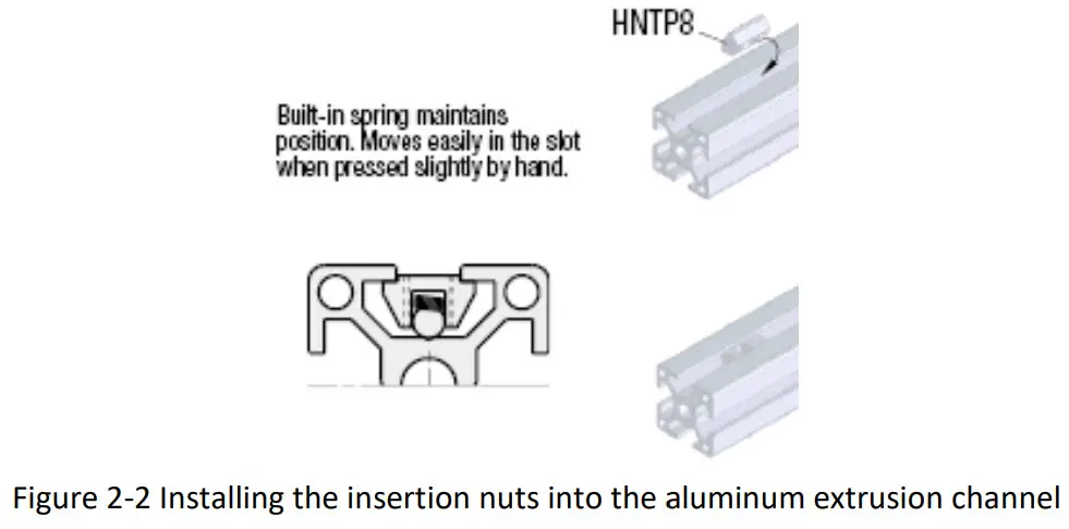
3. Next, prepare to install all components to the Pedestal Mount using the supplied fastener components. The insertion nuts install into the Pedestal Aluminum Extrusion channel and contain a spring-loaded ball feature to hold them in place during assembly. To install the insertion nuts into the Aluminum Extrusion channel, insert the insertion nuts into the extrusion channel at an angle as shown in Figure 2-2, below:
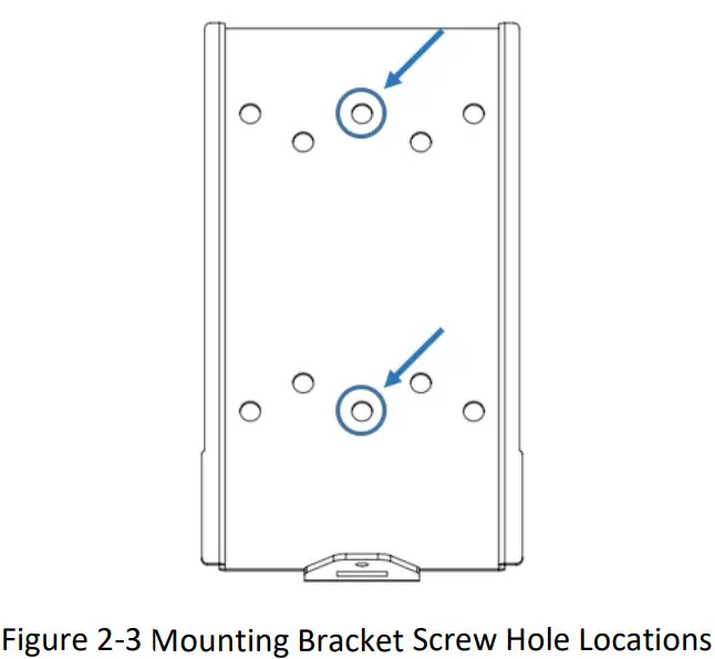
4. To install each item, install the insertion nuts into the extrusion channel at the approximate positions each item will be installed.5. Install the EVSE (charging station box) bracket to one side of the pedestal so that the middle of the bracket is approximately 48 inches from the ground. Only two screws will be used to attach the mounting bracket to the pedestal, the screws should pass (install) through the middle two vertical screw holes of the mounting bracket as shown in Figure 2-3.
6. Next, install the Connector/Plug Holder below the charging station (EVSE) unit.
Input Wiring Connection (Hardwire Connection)
- Choose the appropriate conduit and fitting in accordance with all applicable state, local and national electrical codes and standards. Please note the charging station knock-out size for the input wiring connection is 1” NPT.
- Using the appropriate tool, clamp the wire terminal to the copper wire. For non-insulated terminals, use a heat shrink tube to cover the non-insulated portion of the terminal.
- Connecting the electrical wiring to the charging station.3-1. Place the Charging Station on a flat surface, front cover down with protection under the cover to avoid scratching damage to the cover.3-2. Remove the Charing Station front cover by loosening the (5) Torx screws at the rear of the charging station.3-3. With the (5) Torx screws loosened, hold the front cover in place and flip the charging station over on the flat surface so that the front cover is on top. Once this is completed, lift the charging station front cover and place to the right side of the charging station unit.3-4. With the front cover placed to the side, insert the wire end passing through the conduit and insert them into the input wiring hole. (Use Red wire for L1, Black wire for L2, Green-yellow wire for G). Attach the copper wire on the corresponding terminal block. Use the following wire and torque force when connecting to the input terminal block, using conductor type other than RHH, RHW, and RHW-2 with outer covering.
| Model | Terminal | Conductor | Screw | Rating | Torque | |
| EVOCHARGE iEVSE | L1, L2, G | 8 AWG | M4 | 90C, copper wire | 16 kgf.cm | 13.88 lb-in |
Figure 2-7 Input wiring
![]() CAUTION: To reduce the risk of fire, connect only to a circuit provided with the app ropriatamperes minimum branch circuit overcurrent protection in accordance with the NationalElectrical Code, ANSI/NFPA 70, and the Canadian Electrical Code, Part I, C22.1.
CAUTION: To reduce the risk of fire, connect only to a circuit provided with the app ropriatamperes minimum branch circuit overcurrent protection in accordance with the NationalElectrical Code, ANSI/NFPA 70, and the Canadian Electrical Code, Part I, C22.1.
| Model | Current Setting | Circuit Rating Requirement |
| EVOCHARGE iEVSE | 32A | 40A or greater |
4. Once the input wiring and conduit are connected, reassemble the charging station.4-1. Reinstall the charging station font cover using the following torque force to secure the (5) Torx screws:
| Screw | Torque | |
| M4 | 16 kgf.cm | 13.88 lb-in |
Install Charging Station to Wall Bracket
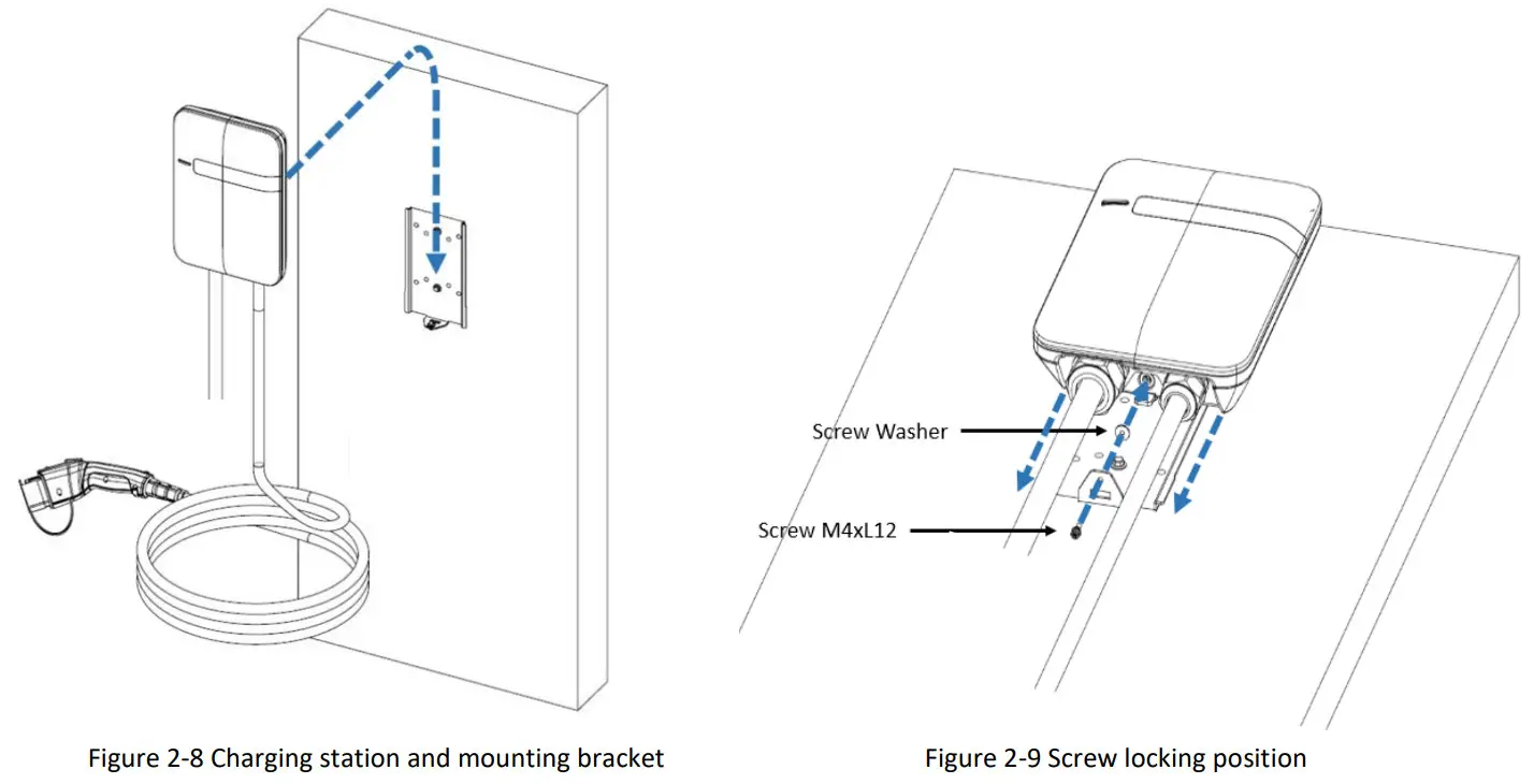
7. As shown in Figures 2-8 & 2-9, mount the charging station onto the mounting bracket and secure the lock screw.4-1. Tighten the installed M4 screw and screw washer to fix the charging station on the mounting bracket.4-2. Use the following torque force:
| Screw | Torque | |
| M4 | 16 kgf.cm | 13.88 lb-in |
Install the Plug and Cable Holder
- Separate the holder from the hook.
- Install the Holder bracket (hook) below the charging station using the supplied fasteners
- Position the plastic holder insert face up and install it into the holder bracket.
- Next, rotate the holder insert down.
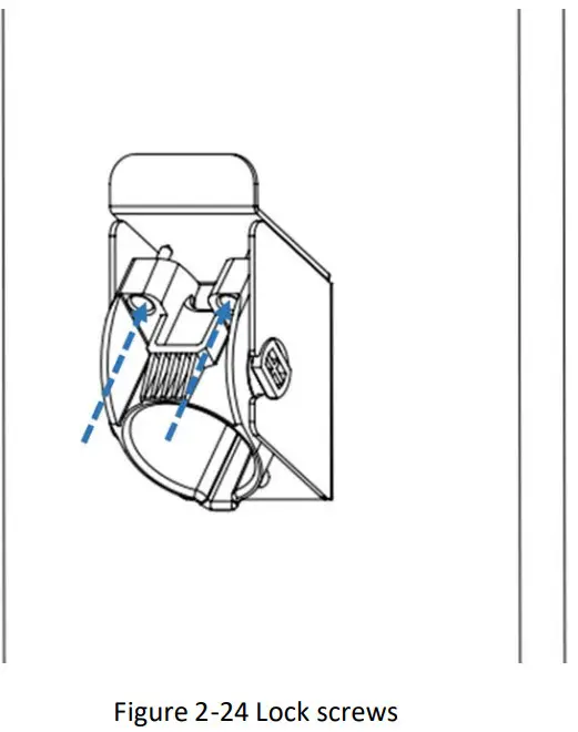
- With the holder insert in the down position, tighten the (2) lock/set Philips screws located at the top of the plastic holder component until snug (do not overtighten). The screws ensure that the plastic holder component remains secured to the holder bracket.
- Insert EV charging connector into the holder.

Operation
Charging Status Indicators
Table 3-1 Charging status indicators
| LED Indicator | Description | Definition |
 |
Not illuminated | Power Off |
 |
Green Steady | Ready |
|
Green Flashing | Flashing green (Fast): Authorized, waiting for forEV to initiate charge event.Flashing green (Slow): Suspend (Occupying) |
|
Blue Flashing | Flashing blue (Slow): Charging |
|
Red Steady | Unrecoverable Fault |
|
Red Flashing | Recoverable Fault |
|
Yellow Steady | Out of Service |
|
Yellow Flashing | Booting / Firmware Upgrade in process |
*Note: In the instance, the “Red Steady” or “Red Flashing” Fault light remains, it is recommended that you:
- Unplug the charging Connector from your EV
- Turn off the power to the Charging Station by switching the upstream circuit breaker to the “OFF” position
- With the circuit breaker in the “OFF” position, wait 1-2 minutes and then switch the upstream circuit breaker back to the “ON” position
- Confirm the Fault light is no longer present. If the Fault light remains, please contact EVOCHARGE.
Charging your Electric Vehicle (EV)
The EVOCHARGE iEVSE Plus supports both “Authorized” (Access Control) operation as well as “Plug and Charge” operation.When the EVOCHARGE iEVSE Plus is configured to require Authorization, the EVSE must first authorize the operation (via RFID card, mobile app, etc.). The EVSE will only supply energy after authorization.
3.2.1 Plug and Charge
This setting must be activated using the web portal – this can be used in instances where access control or payment is not required by the charging station owner.
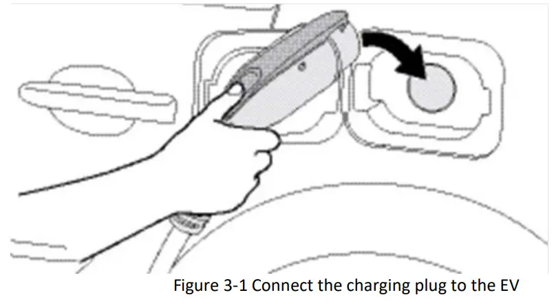
- Insert the charging plug into the EV
- The charging session will automatically commence
 3.2.2 Online Authorization
- Authorization via RFID Card and/or mobile app.
3.2.3 RFID Card Authorization Local and Offline AuthorizationDescription:
- Synchronized with the Central System when EVSE is Online.
- To improve the experience for users, the EVOCHARGE iEVSE Plus can be programmed to allow local authorization when EVSE is offline or not connected to a network. This also supports faster authorization response time in the instance the communication between EVOCHARGE iEVSE Plus and Central System (Network) is slow to respond.
- Insert the charging plug into the EV
- Swipe RFID card
- Wait for the authorization
- The charging session will automatically commence once authorized
Stop Charging
1. Simply unplug the charging station connector from the EV at any time (once the connector button is depressed, the charging session terminates immediately).2. Return the connector to the holder.
3.3.1 Self-Monitoring and Recovery (Auto Restart)When a charging session is interrupted due to a temporary error condition, the charging station will automatically restart charging when the cause of the temporary error condition returns to normal. The status indicator lights remain to flash RED until the error condition is resolved.
- Temporary error conditions include: Over Current, Over Voltage, Under Voltage, and Over Temperature.
- For Over Current (OC) conditions: The charging session will be stopped while OC occurs. After recovery from OC for 30 seconds, the charging station will automatically restart charging three times.
- When the charging session is stopped due to CCID trip, the charging station will try to restart after 15 minutes for 3 times.
3.3.2 Power Outage RecoveryWhen power resumes after an outage, the charging station restarts automatically with a delay ranging from 120 to 720 seconds. The delay is designed to avoid impacting the utility grid when multiple charging stations are in the same area attempting to resume charging simultaneously. Please refer to the STOP CHARGING section for more information.
General Product Care and Use Information
The exterior of the charging station is designed to be waterproof and dustproof (NEMA 4 Outdoor Rated). However, periodic cleaning may be required, depending on local conditions. To ensure proper maintenance of the charging station, follow these guidelines:
- To avoid damaging the finish of the products, only use an automotive-grade soft cleaning cloth and if required a mild soap and water mixture to remove the accumulation of dirt and dust. Do not use cleaning solvents to clean any of the product components. Despite the water-resistance of the enclosure, when cleaning it is preferred to not direct streams of water at the unit – clean with a water damp, automotive-grade soft cleaning cloth.
- Make sure the charging connector is put back in the holster after charging to avoid damage.
- Ensure the power cable is stored on the charging station after use to avoid damage.
- If the power cable or the charging connector is damaged, turn off the charging station supply circuit breaker, do not use the charging station, and please contact EVOCHARGE Customer Support for replacement parts.
- When moving or lifting the unit, always grasp and carry by the charging station plastic body. Never attempt to lift, move, or carry the unit by any of the electrical cables. Improper handling may cause damage to the unit.
report this adFor Additional Products and Accessories visit www.phillpsandtemro.com or contact us at 1-800-328-6108.
References
[xyz-ips snippet=”download-snippet”]