

Installation, Operation & Service Instructions– READ AND SAVE THESE INSTRUCTIONS –
The FireBIRD Compact 20 portable electric heater features multiple power receptacles for connection to common 120VAC outlets. The Compact 20 can output up to 20,000 Btu of clean, safe heat at 250 CFM. The Compact 20’s remote thermostat provides a means to control the temperature in the drying chamber, while its internal temperature cutout ensures safe operation.
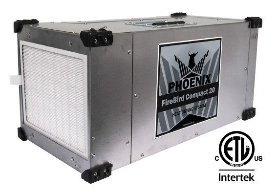
The Phoenix FireBIRD Compact 20
- Listed by ETL to UL Safety Standards
- 15 Amp Operation at 120VAC up to 4 independent circuits (20,000 Btu)
- Remote Thermostat with 25’ connecting wire (included with unit)
- Standard MERV-11 air filter included
- Multiple ducting options
- 8” Outlet Duct, 8” Inlet Duct Optional
- Stainless Steel Cabinet
- Double-Walled, Screened Enclosure for heating elements
- Automatic Internal 140°F Safety Thermal Cutout
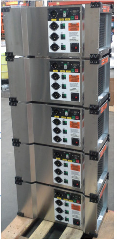
- Stackable for easy storage and transportation

 https://www.youtube.com/user/usephoenix
Phoenix FireBIRD Compact 20PN 4033450Specifications subject to change without notice.TS-78604/19 Rev. C
Serial No. ___________________________Purchase Date ______/______/_____Dealer’s Name ___________________________________
Read the operation and maintenance instructions carefully before using this unit. Proper adherence to these instructions is essential to obtain maximum benefit from your Phoenix FireBIRD Compact 20.
![]() CAUTIONTO PROVIDE CONTINUED PROTECTION AGAINST RISK OF ELECTRIC SHOCK, CONNECT TO PROPERLY GROUNDED OUTLETS ONLY. POWER CORDS MUST BE 12 GA MINIMUM AT 25 FT OR LESS, GREATER THAN 12 GA AT LONGER LENGTHS, AND MUST HAVE A THREE-BLADE GROUNDING-TYPE PLUG.
CAUTIONTO PROVIDE CONTINUED PROTECTION AGAINST RISK OF ELECTRIC SHOCK, CONNECT TO PROPERLY GROUNDED OUTLETS ONLY. POWER CORDS MUST BE 12 GA MINIMUM AT 25 FT OR LESS, GREATER THAN 12 GA AT LONGER LENGTHS, AND MUST HAVE A THREE-BLADE GROUNDING-TYPE PLUG.![]() WARNING
WARNING
- Read all instructions before using this heater.
- DO NOT OPERATE near children or invalids.
- This heater is hot when in use. To avoid burns, do not let bare skin touch hot surfaces. If provided, use handles when moving this heater. Keep combustible materials, such as furniture, pillows, bedding, papers, clothes, and curtains at least 36” (.91 m) from the front of the heater and keep them away from the sides and rear.
- For temporary use only, not for comfort heat. See NFPA 70 Article 590.
- Always unplug unit when not in use.
- DO NOT OPERATE with damaged cord, plug, or after unit malfunctions, has been dropped or damaged in any manner. Return to an authorized service facility for examination or repair.
- Unit Intended for INDOOR USE ONLY; DO NOT USE OUTDOORS.
- This heater is not intended for use in bathrooms, laundry areas and similar indoor locations. Never locate heater where it may fall into a bathtub or other water container.
- DO NOT run cord under carpeting. Do not cover cord with throw rugs, runners, or similar coverings. Do not route cord under furniture or appliances. Arrange cord away from traffic area and where it will not be tripped over.
- To disconnect device, turn controls off, then remove plug from outlet.
- Connect ONLY to properly grounded GFCI outlets.
- DO NOT insert or allow foreign objects to enter any ventilation or exhaust openings as this may cause an ELECTRIC SHOCK or FIRE, or damage the heater.
- To prevent a possible fire, do not block air intakes or exhaust in any manner. Do not use on soft surfaces, such as a bed, where openings may become blocked.
- Device has hot and arcing or sparking parts inside. Do not use in areas where gasoline, paint, or flammable liquids are used or stored.
- Use device only as described in this manual. Any other use not recommended by the manufacturer may cause fire, electric shock, or injury to persons.
- Cords used for 120V service shall be No. 12 AWG minimum size rated not less than 1440 Watts.SAVE THESE INSTRUCTIONSCONSIGNES IMPORTANTES
1 Specifications
Part No. – 4033450Power – Blower Circuit: 1 Amp at 120VAC 60Hz, 1 Phase120VAC 60Hz, 1 Phase Heater Circuits (up to 4): 12 Amp / circuit = 17°F temperature rise/circuit: 5,000 BtuMaximum Heat: 20,000 Btu with 70°F Maximum Temperature Rise at 250 CFMBlower – 250 CFMFilters – Pleated Media MERV-11Duct Options – Outlet – 8” Flex-DuctWarranty – 1 year 100% of Parts and Labor
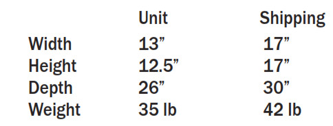
Dimensions
2 Operation
2.1 TransportingThe Phoenix FireBIRD Compact 20 must always be upright when transported by vehicle. The Compact 20 is equipped with rubber corners to permit stacking for storage. If units are transported, they must be secured with restraining straps to prevent damage and possible injury.
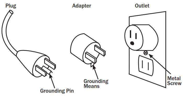
2.2 Electrical RequirementsThe Phoenix FireBIRD Compact 20 requires a 120VAC outlet to power the onboard blower, control and 1st heater circuit. Three aditional heating elements are separately powered by additional cords and receptacles.120VAC heating elements each require cord connection to appropriate receptacles rated at 15A or more. One cord and receptacle are required per heating element. Power cords should be appropriately sized. POWER CORDS MUST BE 12 GA MINIMUM AT 25 FT OR LESS, GREATER THAN 12 GA AT LONGER LENGTHS, AND MUST HAVE A THREE BLADE GROUNDING-TYPE PLUG. An adapter is available for connecting to two-slot receptacles. The green grounding lug extending from the adapter must be connected to a permanent ground such as a properly grounded outlet box. The adapter should not be used if a three-slot grounded receptacle is available.
2.3 DuctingThe Phoenix FireBIRD Compact 20 can be ducted at the inlet, the outlet or both. The FireBIRD Compact 20 inlet and outlet duct are designed to accommodate 8” flexible duct. When selecting flexible ducting keep in mind anticipated outlet temperatures. Air temperature increase is typically 50 to 80 degrees F. Adding ducting decreases airflow which can increase outlet temperatures by up to 40 additional degrees F.
NOTE: It is strongly discouraged to use mylar ducting as this could burn and cause a fire.
2.4 Control PanelFan Mode Switch: This switch allows the user to operate in ‘FAN ON’ or ‘FAN AUTO’ mode. In ‘FAN ON’ mode, the blower will remain on whenever the unit is energized. This mode is recommended for normal operation where constant air circulation is desired. In ‘FAN AUTO’ mode, the blower will only energize when there is a demand for heat from the remote thermostat connection. To use this mode, the CONTROL POWER switch must be set to ‘THERMOSTAT CONTROLLED.’ This mode is recommended for applications that do not require constant air circulation during heating.
Control Power Switch: The CONTROL POWER switch can be used to turn the unit ON, OFF, or set the unit to be controlled by an external thermostat. In ‘ALWAYS ON’ mode, the Compact 20 uses an internal thermostat preset at 140F. Heat will continue to be produced until the air flowing into the inlet reaches 140F. At this point, internal safeties will turn off the heating elements until the inlet air temperature reaches 130F. In ‘THERMOSTAT CONTROLLED’ mode, the Compact 20 looks for a closed circuit at the THERMOSTAT connection on the front of the control panel. Any dry contact switch or the included remote thermostat with 25’ of wire can perform this function.
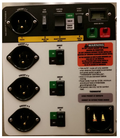
Start/Reset Switch: The START/RESET Switch is used to enable the Compact 20 to produce heat. If at any time power to the control circuit is lost or if a fault condition occurs, the Compact 20 will go into the FAULT/NOT RUNNING mode. Pushing the START/RESET switch will energize the control circuit and restart the Compact 20.
OK/Running Lamp: The OK/RUNNING lamp will illuminate when the control circuit is energized. If the lamp is lit, the Compact 20 is under the control of either the internal or external thermostat (depending on which thermostat is selected with the control power switch). In this state, the heater will be on until it reaches cycling temperatures (130F-140F) and will then self-regulate at this range.
FAULT/NOT RUNNING Lamp: If the FAULT/NOT RUNNING lamp is lit, the contactor control circuit is not energized, which will disable the heater circuits and no heat will be produced.
Hour Meter: The digital hour meter measures the cumulative time that the unit is turned on to tenths of an hour. It stores and displays the total when the unit is unplugged. It resets to zero after 99,999.9 hours of operation.
Heat ON/OFF Switches: These switches individually control the heating elements. Each switch connects and disconnects the power from the receptacle next to it. These switches are lighted to indicate when power is connected and the corresponding heating element is on.
Remote Thermostat Connection: There are two spring loaded terminals for connecting the thermostat wiring on the control panel. Connect one wire to each terminal. For applications where the FireBIRD Compact 20 is placed outside the space to be heated (e.g. ducting heat into a chamber), the 25’ cord allows you to place the thermostat inside the heated space.
In addition to the included thermostat, any dry-contact switch or another type of control that connects the terminals together will cause the heating elements to run. The thermostat circuit is low voltage (24VAC). DO NOT CONNECT POWER TO THE THERMOSTAT TERMINALS.
3 Maintenance
3.1 Air FilterThe Phoenix FireBIRD Compact 20 is equipped with a pleated fabric air filter that must be checked regularly. The standard filter is a MERV-11 high-efficiency filter. Operating the FireBIRD Compact 20 with a dirty or obstructed filter will reduce airflow eventually causing the heating element to shut off. Installing a clean filter or removing the obstruction to restore airflow will allow the heating element to operate again.The filter can generally be vacuumed clean several times before needing replacement. Replacement filters can be ordered from the factory or purchased locally if available.
![]() WARNINGWARNING: DO NOT operate the unit without the filter or with a less effective filter as the heating coils inside the unit could become clogged and require disassembly to clean.
WARNINGWARNING: DO NOT operate the unit without the filter or with a less effective filter as the heating coils inside the unit could become clogged and require disassembly to clean.
4 Service
![]() WARNINGWARNING: Servicing the Phoenix FireBIRD Compact 20 with its high voltage circuitry presents a health hazard which could result in death, serious bodily injury, and/or property damage. Only qualified service people should service this unit.Do not operate the unit without the front cover in place. High voltage is present, heater burnout may result.
WARNINGWARNING: Servicing the Phoenix FireBIRD Compact 20 with its high voltage circuitry presents a health hazard which could result in death, serious bodily injury, and/or property damage. Only qualified service people should service this unit.Do not operate the unit without the front cover in place. High voltage is present, heater burnout may result.
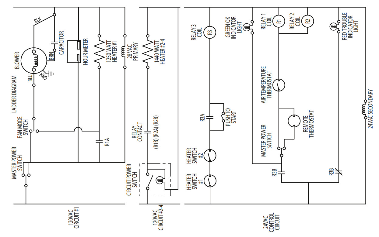
4.1 Technical DescriptionThe compact 20 uses a wound nichrome heating element to provide multiple heat settings depending on the application requirements or available power. The heating elements are operated by contactors operated by a 24VAC control circuit. For safety, there are a set of thermal switches that will de-energize the heating elements if the temperature in the element chamber rises to an unacceptable level caused by lack of airflow or high ambient temperature. An additional safety switch limits the incoming air temperature to approximately 140F. This switch shuts off the heating elements and automatically resets when the temperature falls to approximately 130F.
4.2 TroubleshootingLow voltage heating circuits require dedicated 15A minimum service for each circuit (up to 4 total).
Blower not running
- Unit unplugged, no power to outlet
- Control Switch not working
- Wiring fault inside device
- Defective blower or blower capacitor Blower running but no heat when Ok/Running lamp is on
- Power switch is set to “Thermostat” and no thermostat is connected, or thermostat is open
- High temperature limit reached (140°F)
- Heating relays not operating
- Wiring fault inside device
- Defective heating element, pressure switch, or temperature limit switch
Fault/Not Running lamp illuminated
- Press Start/Reset button
- Reduce the length of inlet or outlet duct (if ducted)
- Check duct for kinks or sharp bends in inlet or outlet duct (if ducted)
- Impeller is obstructed or slow
- Voltage is low
- Create openings in heated cavities to reduce backpressure.
5 Options and Accessories
4033895 – Duct Kit, Compact Heater, 8” inlet (no flex Duct)4027415 – 8” x 25’ Flex Duct4032773 – Cord Kit, (2) 25’ Lighted Cords & (2) 50’ Lighted Cords4030671 – 9” x 11 3/8 x ¾” Mini-Pleated MERV-11 Filter4030733 – Filter Package, 12 PK; 9” x 11 3/8 x ¾” Mini- Pleated MERV-11 Filter4033734 – Filter Package, 4 PK; 9” x 11 3/8 x ¾” Mini-Pleated MERV-11 Filter4030115 – Reed LM 8000 Multi-Function Meter4027327 – Phoenix Remote Thermostat Kit
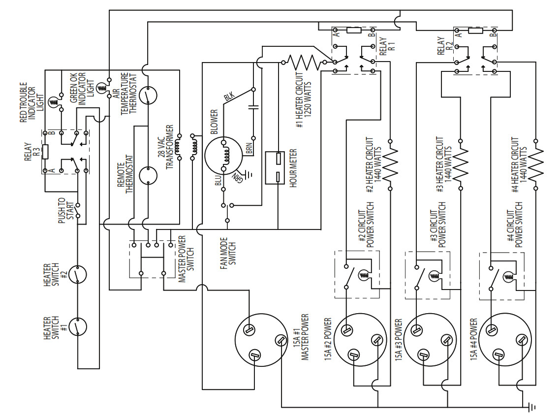
6 Wiring Diagram
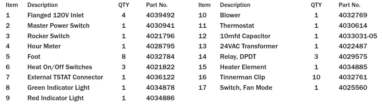
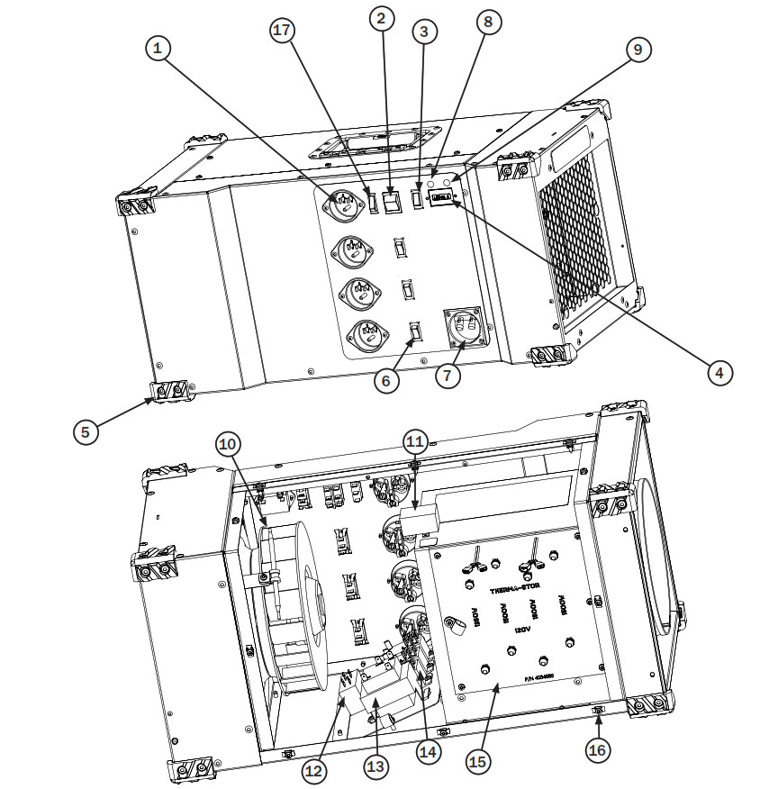
7 Service Parts
Phoenix FireBIRD Compact 20 – Portable Heater
LIMITED WARRANTY
Warrantor:Therma-Stor LLC4201 Lien RdMadison, WI 53704Telephone: 1-800-533-7533
Who Is Covered: This warranty extends only to the original end-user of the Phoenix FireBIRD Compact 20, and may not be assigned or transferred.
Year One: Therma-Stor LLC warrants that, for one (1) year the Phoenix FireBIRD Compact 20 will operate free from any defects in materials and workmanship, or Therma-Stor LLC will, at its option, repair or replace the defective part(s), free of any charge.
End-User Responsibilities: Warranty service must be performed by a Servicer authorized by ThermaStor LLC. If the end-user is unable to locate or obtain warranty service from an authorized Servicer, he should call Therma-Stor LLC at the above number and ask for the Therma-Stor Service Department, which will then arrange for covered warranty service. Warranty service will be performed during normal working hours.
The end-user must present proof of purchase (lease) upon request, by use of the warranty card or other reasonable and reliable means. The end-user is responsible for normal care. This warranty does not cover any defect, malfunction, etc. resulting from misuse, abuse, lack of normal care, corrosion, tampering, modification, unauthorized or improper repair or installation, accident, acts of nature, or any other cause beyond Therma-Stor LLC’s reasonable control.
Limitation and Exclusions: If any Phoenix FireBIRD Compact 20 part is repaired or replaced, the new part shall be warranted for only the remainder of the original warranty period applicable thereto (but all warranty periods will be extended by the period of time if any, that the Phoenix FireBIRD Compact 20 is out of service while awaiting covered warranty service).
UPON THE EXPIRATION OF THE WRITTEN WARRANTY APPLICABLE TO THE PHOENIX FireBIRD Compact 20 OR ANY PART THEREOF, ALL OTHER WARRANTIES IMPLIED BY LAW, INCLUDING MERCHANTABILITY AND FITNESS FOR A PARTICULAR PURPOSE, SHALL ALSO EXPIRE. ALL WARRANTIES MADE BY THERMA-STOR LLC ARE SET FORTH HEREIN, AND NO CLAIM MAY BE MADE AGAINST THERMA-STOR LLC BASED ON ANY ORAL WARRANTY. IN NO EVENT SHALL THERMA- STOR LLC, IN CONNECTION WITH THE SALE, INSTALLATION, USE, REPAIR OR REPLACEMENT OF ANY PHOENIX FireBIRD Compact 20 OR PART THEREOF BE LIABLE UNDER ANY LEGAL THEORY FOR ANY SPECIAL, INDIRECT OR CONSEQUENTIAL DAMAGES INCLUDING WITHOUT LIMITATION WATER DAMAGE (THE END-USER SHOULD TAKE PRECAUTIONS AGAINST SAME), LOST PROFITS, DELAY, OR LOSS OF USE OR DAMAGE TO ANY REAL OR PERSONAL PROPERTY.
Some states do not allow limitations on how long an implied warranty lasts, and some do not allow the exclusion or limitation of incidental or consequential damages, so one or both of these limitations may not apply to you.
Legal Rights: This warranty gives you specific legal rights, and you may also have other rights which vary from state to state.
Phoenix FireBIRD Compact 20 Portable Heater User Manual – Phoenix FireBIRD Compact 20 Portable Heater User Manual –
[xyz-ips snippet=”download-snippet”]