
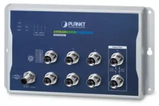
PLANET Wall-Mount Managed Switch WGS-5225-8MT
Package Contents
Thank you for purchasing PLANET Industrial L2+ 8-Port 10/100/1000T M12 Wallmount Managed Switch. The table below shows the model with the number of ports
| Model Name | 10/100/1000T M12 ports, 8-pin X-coded female connector |
| WGS-5225-8MT | 8 |
In the following sections, unless specified, the term “Wall-mount Managed Switch” mentioned in this quick installation guide refers to the above model.Open the box of the Wall-mount Managed Switch and carefully unpack it. The box should contain the following items:
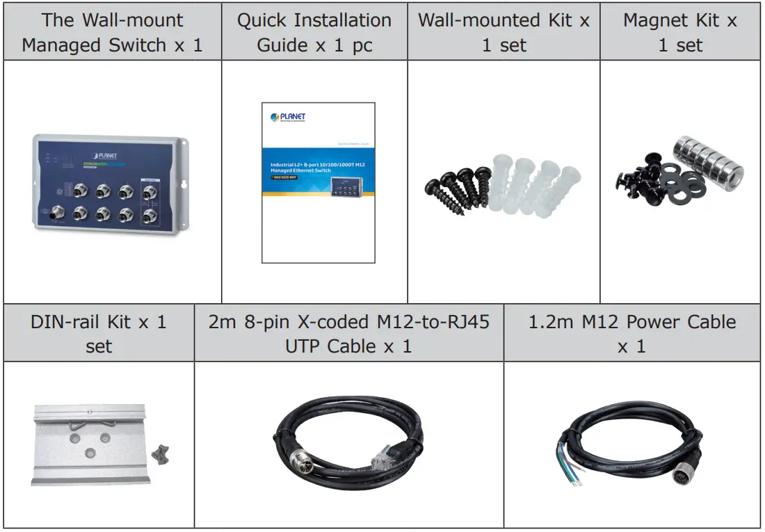
If any item is found missing or damaged, please contact your local reseller for replacement.
M12 X-coded cable
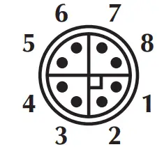
M12 X-coded Connector Pin AssignmentThe WGS-5225-8MT front panel provides eight 10/100/1000BASE-T Ethernet ports in the form of M12 8-pin X-coded female connector. These ports are designed for Ethernet equipment connection through Cat5/5e UTP cables. The M12 8-pin X-coded input interface pinout is shown below:
| Pin | Con |
| 1 | DA+ |
| 2 | DA |
| 3 | DB+ |
| 4 | DB |
| 5 | DD+ |
| 6 | DD |
| 7 | DC |
| 8 | DC+ |
8-pin M12 X-coded Female 10/100/1000T Connector Pin Assignment
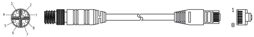
M12 (8-pin, X-coded Male) to RJ45 (8-pin) Straight-through UTP Cabling
| M12 X-coded Male Connector Pin No. | MDI 1000BASE-T Signal ID |
T568B Color |
RJ45 Connector Pin No. |
| 1 | BI_DA+ | white/orange | 1 |
| 2 | BI_DA- | orange | 2 |
| 3 | BI_DB+ | white/green | 3 |
| 4 | BI_DB- | green | 6 |
| 5 | BI_DD+ | white/brown | 7 |
| 6 | BI_DD- | brown | 8 |
| 7 | BI_DC- | White/blue | 5 |
| 8 | BI_DC+ | blue | 4 |
Note: As each Ethernet port of the Wall-mount Managed Switch is running in auto negotiation mode, make sure the Ethernet ports of the corresponding Ethernet devices are also running in auto negotiation mode; otherwise, the Ethernet performance will be poor.
Connecting M12 Cable to the WGS-5225-8MTNote: Follow the steps below to connect M12 cables to the WGS-5225-8MT.
Step 1: Turn counterclockwise to remove the waterproof caps of an M12 connector and power input.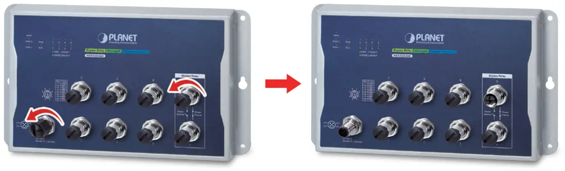
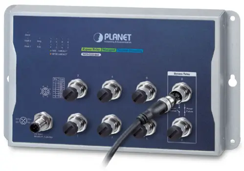
Step 2: Insert the M12 UTP male connector into the M12 female Gigabit Ethernet port of the Wall-mount Managed Switch.
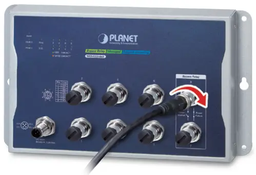
Step 3: Turn clockwise to tighten the cable of the M12 connector and make sure the connection is tight.
Step 4: Insert the M12 power female connector into the M12 male port of the power input.
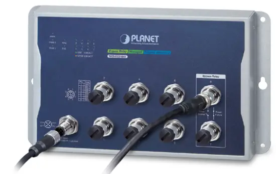
Step 5: Turn clockwise to tighten the cable connecting to the M12 power connector.
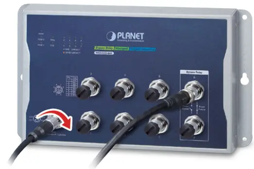
Caution: To have the vibration-proof effect, connectors must be totally tightened.
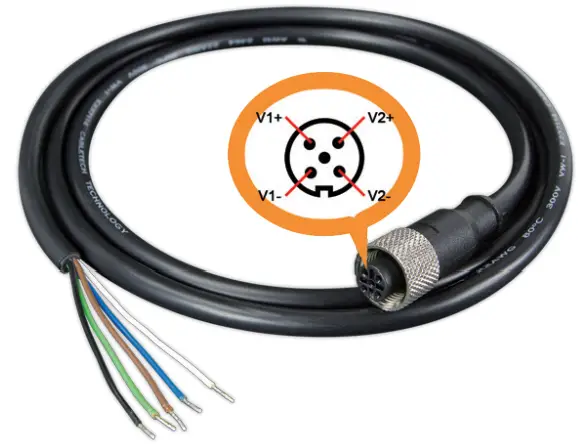
M12 DC Power Cable
Pin AssignmentThe front panel of the Wall-mount Managed Switch provides one M12 DC power 5-pin male connector for DC power input. Please use the power cable with the M12 DC power 5-pin female connector from the Wall-mount Managed Switch package for DC power input. The M12 DC power cable pin assignment is shown below:
| M12 DC power cable pin assignment and wiring code | |
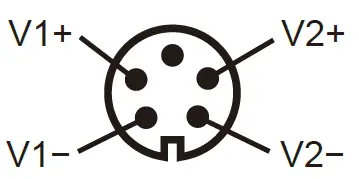 |
V1 positive (+) pin = blue cable |
| V1 negative (-) pin = white cable | |
| V2 positive (+) pin = black cable | |
| V2 negative (-) pin = brown cable |
Note: Make sure you connect the correct power pin to your DC power source.
- The wire gauge for the power cable should be in the range of 12 ~ 24 AWG.
- The DC power input range is 9 ~ 48V DC.
Requirements
- Workstations running Windows XP/2003/Vista/7/8/2008/10, MAC OS X or later, Linux, UNIX, or other platforms are compatible with TCP/IP protocols.
- Workstations are installed with Ethernet NIC (Network Interface Card)
- Ethernet Port Connection
- Network cables — Use network (UTP) cables with M12 (X-coded) and RJ45 connectors.
- The above PC is installed with Web browser.
Note: It is recommended to use Internet Explorer 8.0 or above to access the Wall-mount Managed Switch. If the Web interface of the Wallmount Managed Switch is not accessible, please turn off the antivirus software or firewall and then try it again.
Hardware Installation
Wall Mount Installation
To install the Wall-mount Managed Switch on the wall, simply follow the following steps:
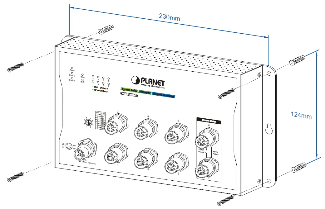
Step 1: It is required 4 holes with 8mm diameter on the wall; the distance between the 2 holes is 230 mm and the line through them must be horizontal.
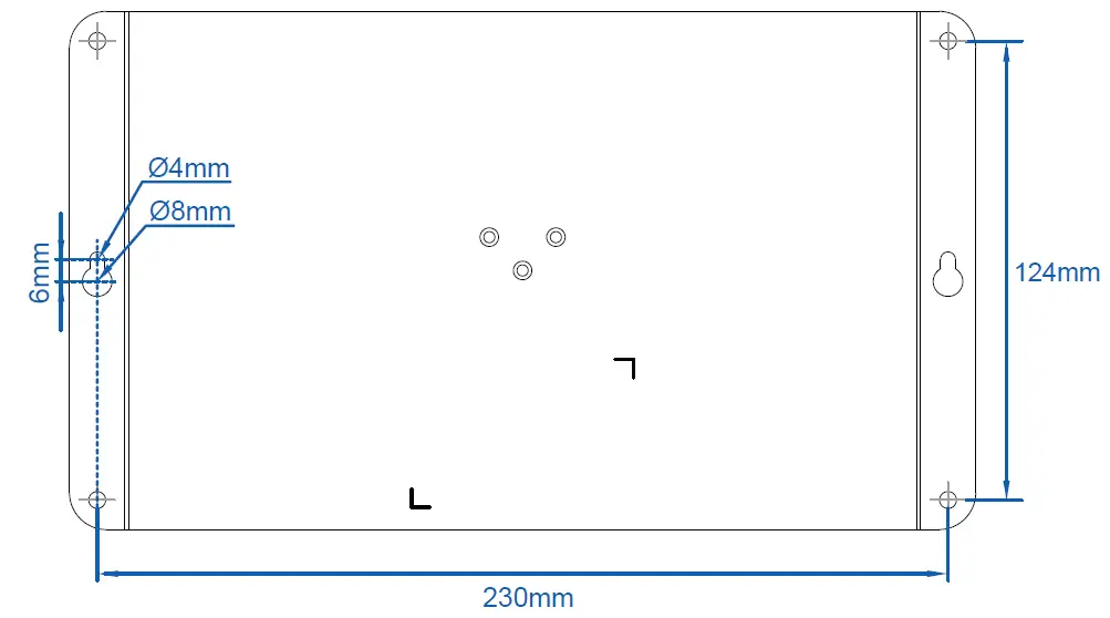
Step 2: Install a conductor pipe inside the board hole and flush the edge of the conductor pipe with the wall surface.Step 3: Screw the bolts into the conductor pipe. The Wall-mount Managed Switch is between bolts and conductor pipe, as shown below.
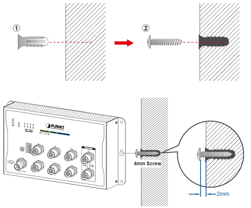
Wall Hanging InstallationTo hang the Wall-mount Managed Switch on the wall, simply follow the following steps:
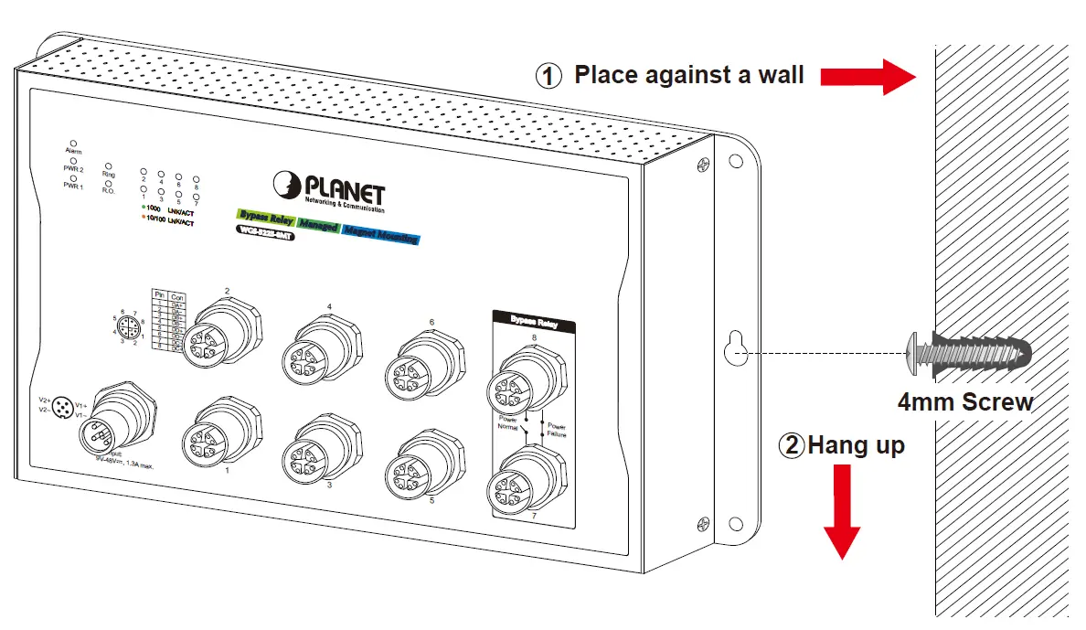
Step 1: Drill 2 holes (one hole on each side) with 8mm diameter on the wall; the distance between the 2 holes is 230 mm and the line through them must be horizontal.Step 2: Place two anchors inside the board hole by hammering them. Then screw the two screws leaving a space of 2mm apart as shown in the circled diagram below.
Step 3: The switch, shown in the picture below, can now be hung on the wall.
Magnet Installation
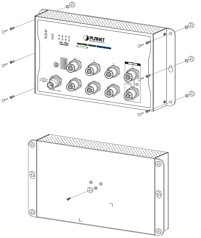
To install the Wall-mount Managed Switch on a magnetic surface, simply follow the following diagram:
Step 1: There are six holes in front, using six sets of magnets to install. Please refer to the following.Step 2: Turn the switch to the back, then screw the magnet to the middle hole.
Caution: Make sure the equipment is securely magnetically-mounted as strong vibration could cause it to drop or break.
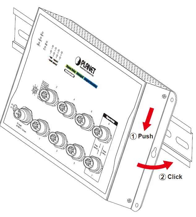
DIN-rail Mounting
The DIN-rail kit is included in the package. When the wall mounting of the Wallmount Managed Switch needs to be replaced with DIN-rail mounting, refer to the following figures to screw the DIN-rail on the Wall-mount Managed Switch. To hang up the Wall-mount Managed Switch, follow the steps below:Step 1: Screw the DIN-rail on the Wall-mount Managed Switch.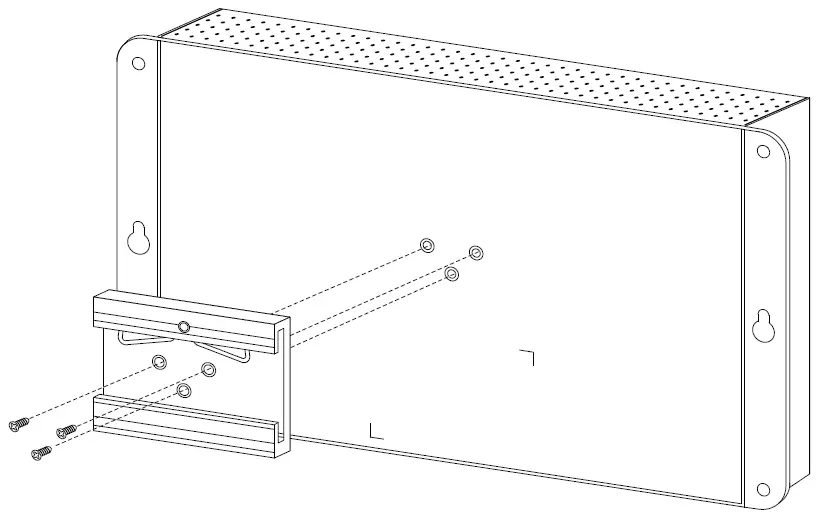
Step 2: Lightly insert the DIN-rail into the track.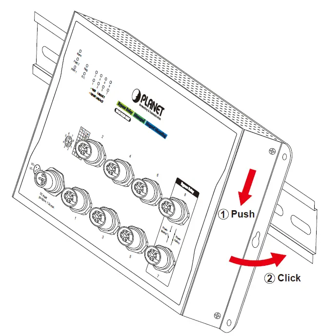
Step 3: Check whether the DIN-rail is tightly on the track.
Web Login
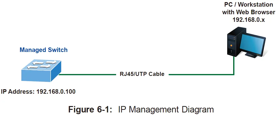
Starting Web Management
The following shows how to start up the Web Management of the Wall-mount Managed Switch. Note the Wall-mount Managed Switch is configured through an Ethernet connection. Please make sure the manager PC must be set to the same IP subnet address.For example, the default IP address of the Wall-mount Managed Switch is 192.168.0.100, then the manager PC should be set to 192.168.0.x (where x is a number between 1 and 254, except 100) and the default subnet mask is 255.255.255.0.
Logging in to the Wall-mount Managed Switch
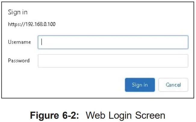
- Use Internet Explorer 8.0 or above Web browser and enter IP address http://192.168.0.100 to access the Web interface.
- When the following dialog box appears, please enter “admin” in both the default user name and password fields. The login screen in Figure 6-2 appears.Default IP Address: 192.168.0.100Default Username: adminDefault Password: admin

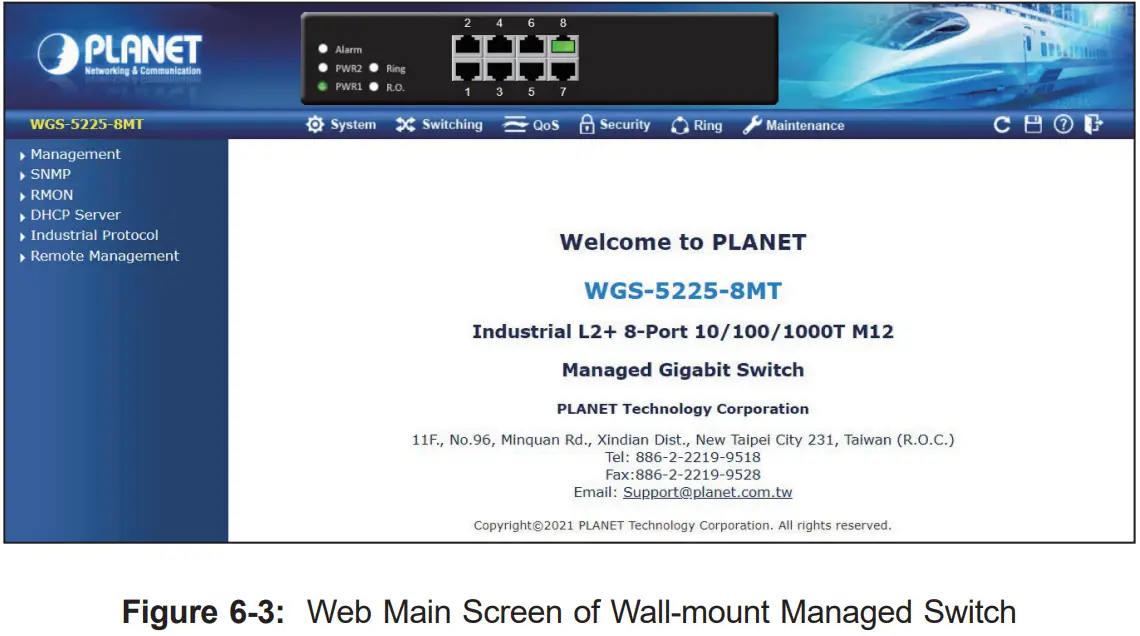
- After entering the password, the main screen appears as Figure 6-3 shows.The Switch Menu on the top of the Web page lets you access all the commands and statistics the Wall-mount Managed Switch provides. The Switch Menu always contains one or more buttons, such as “System”, “Switching”, “Routing”, “QoS”, “Security”, “Ring” and “Maintenance”.If you are not familiar with Switch functions or the related param-eter, press “Help icon” anytime on the Web page to get the help description.
 The Switch Menu on the top of the Web page lets you access all the commands and statistics the Wall-mount Managed Switch provides. The Switch Menu always contains one or more buttons, such as “System”, “Switching”, “Routing”, “QoS”, “Security”, “Ring” and “Maintenance”.
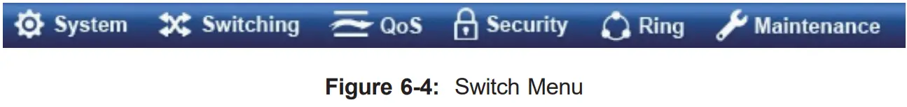 If you are not familiar with Switch functions or the related param-eter, press “Help icon” anytime on the Web page to get the help description.
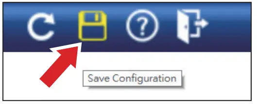
Saving Configuration via the Web
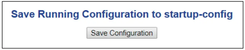
To save all applied changes and set the current configuration as a startup configuration, the startup-configuration file will be loaded automatically across a system reboot.
- Click the Save icon on the top Switch Menu bar.
- Press the “Save Configuration” button.
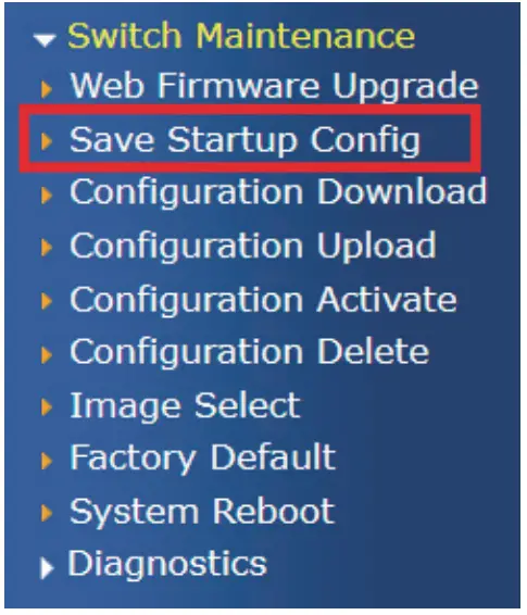
- Or the other way to save the setting is to Click Maintenance, Save Startup Config.
Recovering Back to Default Configuration
IP Address has been changed or admin password has been forgotten –
To reset the IP address to the default IP address “192.168.0.100” or reset the login password to default value, press the reset button on the front panel for about 5 seconds. After the device is rebooted, you can log in the Web interface management within the same subnet of 192.168.0.xx.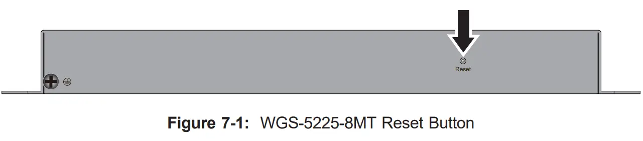
Customer Support
Thank you for purchasing PLANET products. You can browse our online FAQ resource and User’s Manual on PLANET Web site first to check if it could solve your issue. If you need more support information, please contact PLANET switch support team.PLANET online FAQs:https://www.planet.com.tw/en/support/faqSwitch support team mail address: [email protected]WGS-5225-8MT User’s Manual: https://www.planet.com.tw/en/support/downloads?&method=keyword&keyword=WGS&view=3#list
 report this ad
Copyright © PLANET Technology Corp. 2021Contents are subject to revision without prior notice.PLANET is a registered trademark of PLANET Technology Corp. All other trademarks belong to their respective owners.
[xyz-ips snippet=”download-snippet”]