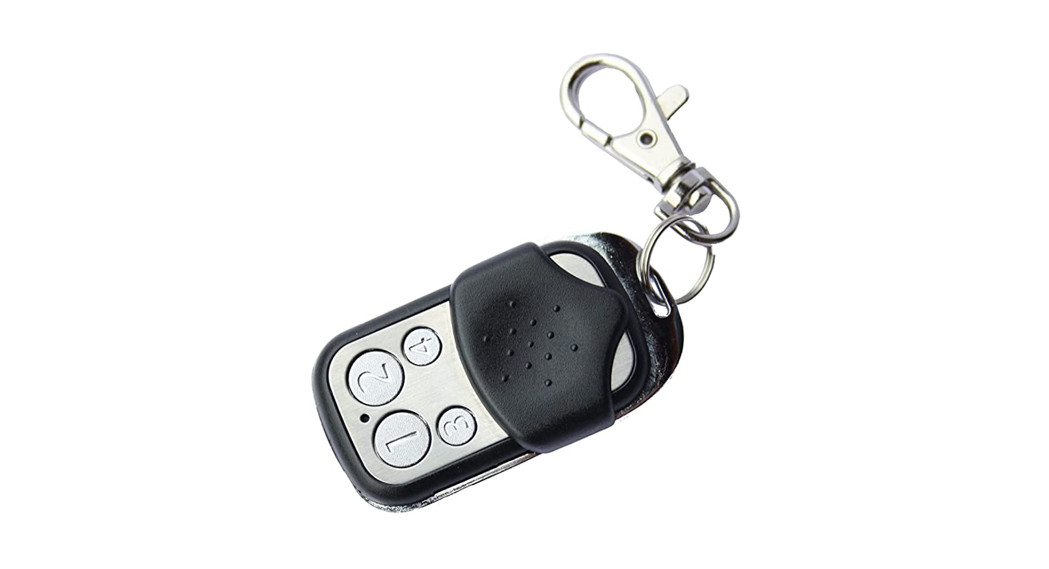
![]() PoppPopp 4 Button Key Chain ControllerSKU: POPE009204
PoppPopp 4 Button Key Chain ControllerSKU: POPE009204

![]()
Quickstart
This is a secure Simple Remote Control for Europe. To run this device please insert fresh 1 * CR2032 batteries. Please make sure the internal battery is charged.This wireless ZWave wall controller can act in two different modes that are activated with the first configuration action after factory default:
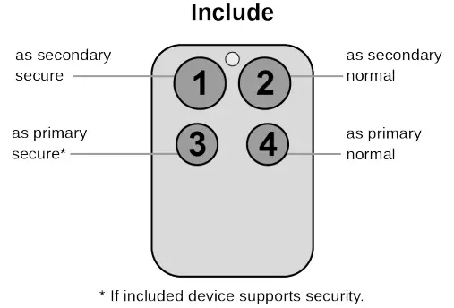
- Pushing Button 1 for one sec. (red/green blink) adds the KFOB remote control to an existing network as a secondary controller. The four b will send activate 4 different scenes (Central Scene Command) to the central controller (A central controller for the Z-Wave network is required.).
- Pushing Button 3 for one sec. (green blink) adds a new Z-Wave actuator device to the controller who becomes the primary controller of the network. The connected new device (actuator) can be controlled using the two buttons left (Button 1 = up/on/open, Button 3 = down/off/closed).
After the first act, you can further manage and configure the wall controller using the management mode. To activate this management mode push buttons for one second simultaneously (green blinks slowly). The buttons will have different functions then (see Installation Guidelines).Attention:For convenience reasons, some special short cut applies IF and only IF the KFOB is the primary controller of the network: The first device included in a button group will define the commands sent out by this group regardless of the default value of the configuration parameters 11-14. the device is a door lock the button group will turn into door lock control (value=7). For dimmers and motor controls the value changes into Multilevel Switch (value=1). All other devices will turn the button group into Basic control (value=2). All configuration values can be changed if needed. When KFOB is pri controller the very first device included will be automatically put into button group A and the command set will change according to the rules just me All other devices need to be put in button groups manually.
Important safety information
Please read this manual carefully. Failure to follow the recommendations in this manual may be dangerous or may violate the law. The manufacturer, import distributor, and seller shall not be liable for any loss or damage resulting from failure to comply with the instructions in this manual or any other material. Use equipment only for its intended purpose. Follow the disposal instructions. Do not dispose of electronic equipment or batteries in a fire or near open heat sou
What is Z-Wave?
Z-Wave is the international wireless protocol for communication in the Smart Home. This device is suited for use in the region mentioned in the Quickstart sZ-Wave ensures reliable communication by reconfirming every message (two-way communication) and every mains powered node can act as a repeat node (meshed network) in case the receiver is not in direct wireless range of the transmitter.
![]() This device and every other certified Z-Wave device can be used together with any other certified Z-Wave device regardless of brand and origin as long as both are suited for the same frequency range.If a device supports secure communication it will communicate with other devices secure as long as this device provides the same or a higher level of security. Otherwise, it will automatically turn into a lower level of security to maintain backward compatibility.For more information about Z-Wave technology, devices, white papers, etc. please refer to www.z-wave.info.
This device and every other certified Z-Wave device can be used together with any other certified Z-Wave device regardless of brand and origin as long as both are suited for the same frequency range.If a device supports secure communication it will communicate with other devices secure as long as this device provides the same or a higher level of security. Otherwise, it will automatically turn into a lower level of security to maintain backward compatibility.For more information about Z-Wave technology, devices, white papers, etc. please refer to www.z-wave.info.
Product Description
The Secure Key Fob Controller is a 4 button Z-Wave device capable to act both as a primary or secondary controller. The four buttons can control other Z-Wave devices such as switches, dimmer, and even door locks directly. Various options – configurable configuration commands – define the actions and the commands used for this control. It is possible to use two sets of buttons (one of on/open/up and one for off/closed/down) or 4 single buttons to control 4 different groups of devices.The controller also allows triggering scenes in a central controller. Again different modes can be configured to adapt to the various implementations of different central controllers in the market.Control options also include special modes like “all on/off” or always controlling the Z-Wave device in proximity to the fob.The device supports secure communication when included with enhanced security option and when communicating to a device also supporting enhance option. Otherwise, the device will automatically turn into normal communication to maintain backward compatibility.
Prepare for Installation / Reset
Please read the user manual before installing the product.In order to include (add) a Z-Wave device to a network, it must be in the factory default state.Please make sure to reset the device into factory default. You ca this by performing an Exclusion operation as described below in the manual. Every Z-Wave controller is able to perform this operation however it is recommended the primary controller of the previous network make sure the very device is excluded properly from this network.Reset to factory defaultThis device also allows being reset without any involvement of a Z-Wave controller. This procedure should only be used when the primary controller is nopeEnter management mode by push all four buttons together for one second – green led blinks slowly), then hit button 3 followed by keeping button 4 pushed seconds. In the first five seconds, the green LED still blinks followed by a long red, shot green sequence. Once LEDs go off, reset was executed.Safety Warning for BatteriesThe product contains batteries. Please remove the batteries when the device is not used. Do not mix batteries of different charging levels or different brands.
Installation
The device comes ready to use with a battery already installed.
 For battery change, the device needs to be opened by removing the three little screws on the backside of the device. Use a screwdriver or any other usable gently push out the battery as shown in the picture. During reassembly watch the position of the white rubber and make sure the silver buttons fit exactly in the nipples of the rubber.The device can be operated in two different modes: the operation mode and the management mode:Operation Mode: This is the mode where the device is controlling other devices.Management Mode: The device is turned into management mode by pushing all four buttons for one second. A blinking LED indicates the mana mode. In the management mode buttons of the device have different functions. If no further action is performed the device will turn back to the normal mo after 10 sec. Any management action terminates the management mode as well.In management mode the following actions can be performed:
- Button 1 – Inclusion/Exclusion: Every inclusion or exclusion attempt is confirmed by hitting this button. Single Click is used for standard inclusion and excl double click is used for network-wide inclusion. With this operation the device can be included in a Z-Wave Network from any physical location in the This requires a primary controller supporting network-wide inclusion. This mode lasts for 20 seconds and stops automatically. Any button press stops the as well.
- Button 2 – Sends Node Information Frame and Wake up Notification. (see explanation below)
- Button 3 – Activates the primary controller management menu. The following sub-menu items are available:•Button 3 followed by the short click of button 1: Start Secure Inclusion•Button 3 followed by the short click of button 2: Start Unsecure Inclusion•Button 3 followed by the short click of button 3: Start Exclusion•Button 3 followed by the short click of button 4: Start Primary Handover•Button 3 followed by pushing button 4 for 5 seconds: Factory Default Reset. After clicking on button 3 keep button 4 pushed for 4 seconds
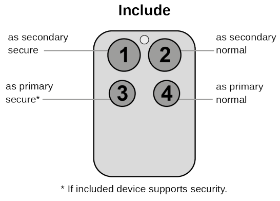
- Button 4 – Enters into Association mode to assign target devices to one of the four associations. Refer to the manuals section about association for moreinformation on how to set and unset association groups.In factory default mode pushing one of the four buttons for 1 sec will start different inclusion modes:•Button 1: Include KFOB as a secondary controller•Button 2: Include KFOB as a secondary controller – nonsecure•Button 3: Include new device into KFOBS network•Button 4: Include new device into KFOBS network – non-secure
The process for buttons 1 and 2 are indicated with fast read/green blinking, the process for buttons 3 and 4 shows a fast green blinking. Every button push stops theprocess. This fast inclusion only works when the device is in factory default.
 Attention: For convenience reasons some special short cut apply IF and only IF the KFOB is the primary controller of the network: The first device inc a button group will define the commands sent out by this group regardless of the default value of the configuration parameters 11-14. If the device is a d the button group will turn into door lock control (value=7). For dimmers and motor controls the value changes into Multilevel Switch Control (value=1). Allot will turn the button group into Basic control (value=2). All configuration values can be changed if needed. When KFOB is the primary controller the very first de included will be automatically put into button group A and the command set will change according to the rules just mentioned. All other devices need to button groups manually.
Inclusion/Exclusion
On factory default, the device does not belong to any Z-Wave network. The device needs to be added to an existing wireless network to communicate wi devices of this network. This process is called Inclusion.Devices can also be removed from a network. This process is called Exclusion. Both processes are initiated by the primary controller of the Z-Wave network controller are turned into exclusion respective inclusion mode. Inclusion and Exclusion is then performed doing a special manual action right on the device.Inclusion
- Start the management mode (all buttons for 5 seconds) ( green LED is blinking) 2. Press key 1 short
Exclusion
- Start the management mode (all buttons for 5 seconds) ( green LED is blinking)
- Press key 1 short
Product Usage
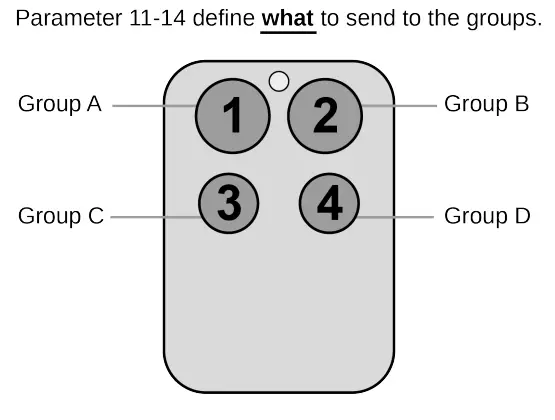
Depending on the button mode and operating modes configured using the configuration parameters the key fob can be used in different ways.Button modes:4 Groups are controlled with single button (parameter 1/2 = 0) The four buttons 1-4 control one single control group each: 1->A, 2->B, 3->C, 4->D. Singturns devices in the control group on, double click turns them off. Click and hold can be used for dimming.
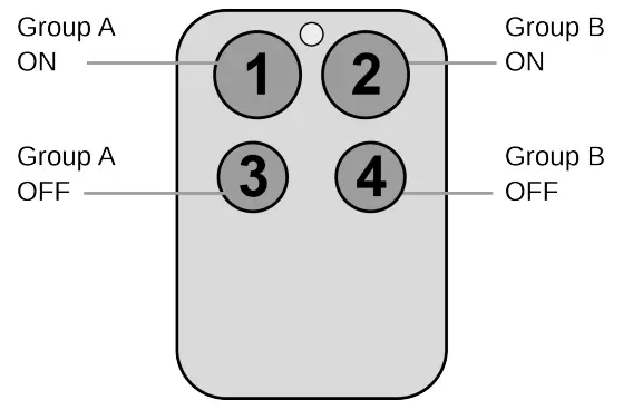
2 Groups are controlled with two buttons (parameter 1/2 = 1) The buttons 1 and 3 control group A (button one turns on, button three turns of buttons 2 and 4 control the control group B (button two turns on, button four turns off). In case dimmers are controlled, holding down the larger button will di holding down the smaller button will dim down the load. Releasing the button will stop the dimming function.
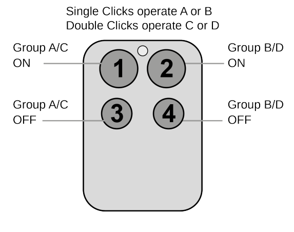
 4 Groups are controlled with two buttons and double click (parameter 1/2 = 2) This mode enhances the previous model and allows to control of two further groups C and D using double clicks.
Operating modes:The device supports 8 different operating modes – this means the kind of command sent out when pushing a button. Operating modes either directly control devices or issue various scene activation commands to a central controller. Operating modes for direct device control are:
- Direct Control of associated devices with On/Off/Dim commands (parameter 11…14 = 1). Devices are controlled using Basic Set On/Off command Switch-Multilevel Dim Start/Stop. This mode implements communication pattern 7.
- Direct Control of associated devices with only On/Off commands (parameter 11…14 = 2). Devices are controlled using only Basic Set On/Off comma On dimming Up event On is sent, on dimming Down Off is sent. This mode also implements communication pattern 7.
- Switch All commands (parameter 11…14 = 3) In this mode an all neighboring devices will receive Switch-All Set On/Off command and interpret it acco to their membership in Switch-All groups. This mode implements communication pattern 7.
- Direct Control of Devices in proximity (parameter 11…14 = 6). Basic Set and Switch-Multilevel Dim commands are sent to a device in proximity (50.. cm) from the Fob. Attention: In case there are more than one Z-Wave devices nearby all these devices may be switched. For this reason, the proximity fu should be handled with care. This mode implements communication pattern 7
- Door Lock Control (parameter 11…14 = 7) This mode allows direct control (open/close) of electronic door locks using secure communication. The mod implements communication pattern 7.Operating modes for scene activation are:
- Direct Activation of preconfigured scenes (parameter 11…14 = 5) Associated devices in an association group are controlled by individual commands defines by the Z-Wave command class ? Scene Controller Configuration?. This mode enhances mode Direct Control of associated devices with On/Off/D commands and implements communication patterns 6 and 7. Please turn the button mode to “separate” to allow different a scene ID on every button.
- Scene Activation in IP Gateway (parameter 11…14 = 4) If configured correctly the buttons can trigger a scene in a gateway. The scene number trigger combination of the group number and the action performed on the button and has always two digits. The group number defines the upper digit of the site number, the action the lower digit. The following actions are possible:
1 = On2 = Off3 = Dim Up Start 4 = Dim Down Start5 = Dim Up Stop6 = Dim Down Stop Example: Clicking/double-clicking the button will issue scene triggers, scene 11 (button 1 click, event on), scene 12 (button double click 1, event off, sing button control is used in this example)
- Activation of Central Scenes (parameter 11…14 = 8, Default) Z-Wave Plus introduces a new process for scene activation – the central scene control. a button and releasing a button send a certain command to the central controller using the lifeline association group. This allows reacting both on-button and button release. This mode implements communication patterns 6 but requires a central gateway supporting Z-Wave Plus.
LED Indication
- Confirmation – green 1-sec
- Failure – red 1 sec
- Button press confirmation – green 1/4 sec
- Waiting for Network Management mode selection – slow green blinks
- Waiting for group selection in Association Set Mode – green fast blink
- Waiting for primary controller function selection – green fast blink Waiting for NIF in Association Set Mode – green-red-off blink
Node Information Frame
The Node Information Frame (NIF) is the business card of a Z-Wave device. It contains information about the device type and the technical capabilities. The and exclusion of the device is confirmed by sending out a Node Information Frame. Besides this, it may be needed for certain network operations to send out Information Frame. To issue a NIF execute the following action:Pressing Button 2 in management mode will issue a Node Information Frame.
Communication to a Sleeping device (Wakeup)
This device is battery-operated and turned into a deep sleep state most of the time to save battery life. Communication with the device is limited. In order to communicate with the device, a static controller C is needed in the network. This controller will maintain a mailbox for the battery-operated devices and store commands that can not be received during the deep sleep state. Without such a controller, communication may become impossible and/or the battery life significantly decreased.This device will wake up regularly and announce the wakeup state by sending out a so-called Wakeup Notification. The controller can then empty the mailbox Therefore, the device needs to be configured with the desired wakeup interval and the node ID of the controller. If the device was included by a static control controller will usually perform all necessary configurations. The wakeup interval is a tradeoff between maximal battery lifetime and the desired responses o device. To wakeup the device please perform the following action:The device will stay awake right after inclusion for 10 seconds allowing the controller to perform certain configurations. It is possible to manually wake up the pushing button 2 in management mode.The minimum allowed wakeup time is 240s but it’s strongly recommended to define a much longer interval since the only purpose of a wakeup should be of the battery status or an update of the child protection settings. The device has a periodic wake-up function however this function is disabled by config parameter #25. This will protect the battery in case the controller is accidentally configuring a wake-up interval. A wakeup of the fob outside the range of the co-lead to lots of unsuccessful communication attempts draining the battery. Defining Node ID of 0 as a destination of the Wake-up Notification will disable the wakeup function as well.
Quick troubleshooting
Here are a few hints for network installation if things don’t work as expected.
- Make sure a device is in a factory reset state before including. In doubt exclude before include.
- If inclusion still fails, check if both devices use the same frequency.
- Remove all dead devices from associations. Otherwise, you will see severe delays.
- Never use sleeping battery devices without a central controller.
- Don’t poll FLIRS devices.
- Make sure to have enough mains powered devices to benefit from the meshing
Association – one device controls another device
Z-Wave devices control other Z-Wave devices. The relationship between one device controlling another device is called association. In order to control a dif device, the controlling device needs to maintain a list of devices that will receive controlling commands. These lists are called association groups and they a related to certain events (e.g. button pressed, sensor triggers, …). In case the event happens all devices stored in the respective association group will receive the same wireless command, typically a ‘Basic Set’ Command.Association Groups:
| Group Number | Maximum Nodes | Description |
| 1 | 10 | Lifeline |
| 2 | 10 | Control Group A |
| 3 | 10 | Control Group B |
| 4 | 10 | Control Group C |
| 5 | 10 | Control Group D |
Special Operations as Z-Wave Controller
As long as this device is not included in a Z-Wave network of a different controller it is able to manage its own Z-Wave network as the primary controller. As a controller, the device can include and exclude other devices in its own network, manage associations, and reorganize the network in case of problems. The controller functions are supported:Inclusion of other devicesCommunication between two Z-Wave devices only works if both belong to the same wireless network. Joining a network is called inclusion and is initiated by the controller. The controller needs to be turned into the inclusion mode. Once in this inclusion mode, the other device needs to confirm the inclusion – typically b a button.If the current primary controller in your network is in special SIS mode this and any other secondary controller can also include and exclude devices.To become primary a controller has to be reset and then include a device.For the Inclusion of Z-Wave devices into the own network the following two options exist:
- In factory-default state only: Hit Button 3 (secure) or button 4 (normal) to turn the controller into an inclusion state. Consult the manual of the new device to start the inclusion process.
- Always: Turn into management mode by pressing all 4 buttons for 5 seconds. The green LED will start blinking slowly. Now hit button 3 to activate the p controller functions. The green LED will blink faster. Now Hit Button 1 (secure) or button 2 (normal) to turn the controller into an inclusion state. Consult the new device on how to start the inclusion process.
Exclusion of other devicesThe primary controller can exclude devices from the Z-Wave network. During exclusion, the relationship between the device and the network of this controlled terminated. No communication between the device and other devices still in the network can happen after a successful exclusion. The controller needs to b into the exclusion mode. Once in this exclusion mode, the other device needs to confirm the exclusion – typically by pressing a button.Attention: Removing a device from the network means that it is turned back into factory default status. This process can also exclude devices from their previous network.Turn into management mode by pressing all 4 buttons for 5 seconds. The green LED will start blinking slowly. Now hit button 3 to activate the primary control functions. The green LED will blink faster. Now Hit Button 3 again to turn the controller into an exclusion state. Consult the manual of the new device on how to sta the exclusion process.The shift of Primary Controller RoleThe device can hand over its primary role to another controller and become the secondary controller.Turn into management mode by pressing all 4 buttons for 5 seconds. The green LED will start blinking slowly. Now hit button 3 to activate the primary control functions. The green LED will blink faster. Now Hit Button 4 to turn the controller into primary shift mode. Consult the manual of the new device on how to start the shifting process for the new primary controller.Management of Association in the controllerTo control a Z-Wave device from the Key Fob the node ID of this device needs to be assigned to one of the four association groups. This is a three-step pro
- Turn the Key Fob into management mode and hit button 4 within 10 sec. (LED is blinking green when management mode is reached)
- Within 10 sec. push the button you like the Z-Wave actuator to be assigned with. After 10 sec. the device goes back to sleep. Single click means ad this association group, a double click means removing the node selected in step (3) from this association group
- Find the Z-Wave actuator you like to control by the key fob. Hit the button on the device to issue a Node Information Frame within 20 sec. It a common to hit a control button one or three times. Please consult the manual of the device to be controlled for more information on how to issue a Node Informa Frame. Any button press on Key Fob at this stage will terminate the process.
Configuration Parameters
Z-Wave products are supposed to work out of the box after inclusion, however, certain configurations can adapt the function better to user needs or unlock fu enhanced features.IMPORTANT: Controllers may only allow configuring signed values. In order to set values in the range 128 … 255 the value sent in the application shall bet value minus 256. For example: To set a parameter to 200it may be needed to set a value of 200 minus 256 = minus 56. In the case of a two-byte value, the same applies Values greater than 32768 may need to be given as negative values too.Parameter 1: Button 1 and 3 pair modeIn separate mode button 1 works with Group A, button 3 with Group C. Click is ON, Hold is dimming UP, Double click is OFF, Click-Hold is dimming DOWN button 1/3 are UP/DOWN correspondingly. Click is ON/OFF, Hold is dimming UP/DOWN. Single clicks work with Group A, double click with Group C. Size: 1 Byte, Default Value: 1
| Setting | Description |
| 0 | Separately |
| 1 | In pair without double clicks |
| 2 | In pair with double clicks |
Parameter 2: Button 2 and 4 pair modeIn separate mode button, 2 works with control group B, button 4 with control group D. Click is ON, Hold is dimming UP, Double click is OFF, Click-Hold is dirDOWN. In pair button, B/D are UP/DOWN correspondingly. Click is ON/OFF, Hold is dimming UP/DOWN. Single clicks work with Group B, double click witSize: 1 Byte, Default Value: 1
| Setting | Description |
| 0 | Separately |
| 1 | In pair without double clicks |
| 2 | In pair with double clicks |
Parameter 11: Command to control Group AThis parameter defines the command to be sent to devices of control group A when the related button is pressed.Size: 1 Byte, Default Value: 8
| Setting | Description |
| 0 | Disable |
| 1 | Switch on/off and Dim (send Basic Set and Switch Multilevel) |
| 2 | Switch on/off only (send Basic Set) |
| 3 | Switch all |
| 4 | Send scenes |
| 5 | Send preconfigured scenes |
| 6 | Control devices in proximity |
| 7 | Control door lock |
| 8 | Central scene to the gateway (default) |
Parameter 12: Command to control Group BThis parameter defines the command to be sent to devices of control group B when the related button is pressed.Size: 1 Byte, Default Value: 8
| Setting | Description |
| 0 | Disable |
| 1 | Switch on/off and Dim (send Basic Set and Switch Multilevel) |
| 2 | Switch on/off only (send Basic Set) |
| 3 | Switch all |
| 4 | Send scenes |
| 5 | Send preconfigured scenes |
| 6 | Control devices in proximity |
| 7 | Control door lock |
| 8 | Central scene to the gateway (default) |
Parameter 13: Command to control Group CThis parameter defines the command to be sent to devices of control group C when the related button is pressed.Size: 1 Byte, Default Value: 8
| Setting | Description |
| 0 | Disable |
| 1 | Switch on/off and Dim (send Basic Set and Switch Multilevel) |
| 2 | Switch on/off only (send Basic Set) |
| 3 | Switch all |
| 4 | Send scenes |
| 5 | Send preconfigured scenes |
| 6 | Send preconfigured scenes |
| 7 | Control door lock |
| 8 | Central scene to the gateway |
Parameter 14: Command to control Group DThis parameter defines the command to be sent to devices of control group D when the related button is pressed.Size: 1 Byte, Default Value: 8
| Setting | Description |
| 0 | Disable |
| 1 | Switch on/off and Dim (send Basic Set and Switch Multilevel) |
| 2 | Switch on/off only (send Basic Set) |
| 3 | Switch all |
| 4 | Send scenes |
| 5 | Send preconfigured scenes |
| 6 | Control devices in proximity |
| 7 | Control door lock |
| 8 | Central scene to the gateway (default) |
Parameter 21: Send the following switch all commandsSize: 1 Byte, Default Value: 1
| Setting | Description |
| 1 | Switch off only |
| 2 | Switch on only |
| 255 | Switch all on and off |
Parameter 22: Invert buttonsSize: 1 Byte, Default Value: 0
| Setting | Description |
| 0 | No |
| 1 | Yes |
Parameter 25: Blocks wake up even when Wake Up Interval is setIf the KFOB wakes up and there is no controller nearby, several unsuccessful communication attempts will drain the battery.Size: 1 Byte, Default Value: 0
| Setting | Description |
| 0 | Wake up is blocked |
| 1 | Wake up is possible if configured accordingly |
 report this ad
Parameter 30: Send unsolicited battery report on Wake UpSize: 1 Byte, Default Value: 1
| Setting | Description |
| 0 | No |
| 1 | To the same node as Wake Up Notification |
| 2 | Broadcast to neighbors |
Technical Data
| Dimensions | 0.0550000×0.0300000×0.0150000 mm |
| Weight | 30 gr |
| Hardware Platform | ZM5202 |
| EAN | 2E+10 |
| IP Class | IP 20 |
| Battery Type | 1 * CR2032 |
| Device Type | Simple Remote Control |
| Generic Device Class | Portable Controller |
| Network Operation | Portable Controller |
| Firmware Version | 01.00 |
| Z-Wave Version | 3.63 |
| Certification ID | ZC10-15050016 |
| Z-Wave Product Id | 0x0154.0x0100.0x0301 |
| Frequency | Europe – 868,4 Mhz |
| Maximum transmission power | 5 mW |
Supported Command Classes
|
|
Controlled Command Classes
|
|
Explanation of Z-Wave specific terms
- Controller –– is a Z-Wave device with capabilities to manage the network. Controllers are typically Gateways, Remote Controls, or battery-operated wall controllers.
- Slave — is a Z-Wave device without capabilities to manage the network. Slaves can be sensors, actuators, and even remote controls.
- Primary Controller –– is the central organizer of the network. It must be a controller. There can be only one primary controller in a Z-Wave network.
- Inclusion — is the process of adding new Z-Wave devices into a network.
- Exclusion — is the process of removing Z-Wave devices from the network.
- Association — is a control relationship between a controlling device and a controlled device.
- Wakeup Notification — is a special wireless message issued by a Z-Wave device to announces that is able to communicate.
- Node Information Frame — is a special wireless message issued by a Z-Wave device to announce its capabilities and functions.
(c) 2020 Z-Wave Europe GmbH, Antonstr. 3, 09337 Hohenstein-Ernstthal, Germany,All rights reserved, www.zwave.eu.The template is maintained by Z-Wave Europe GmbH.The product content is maintained by Z-Wave Europe GmbH,Support team, [email protected].Last update of the product data: 2017-12-0110:22:03http://manual.zwave.eu/backend/make.php?lang=en&sku=POPE009204Pagina 10 van 10
References
[xyz-ips snippet=”download-snippet”]