
PoppSmart Outdoor PlugSKU: POPE70039706-10-2020 17:01


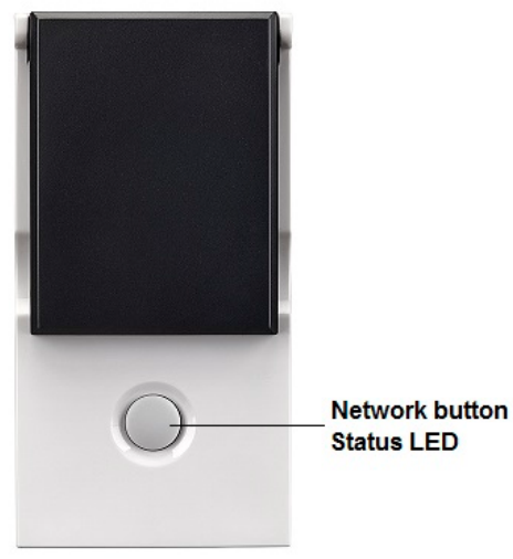
QuickstartThis is a secure On/Off Power Switch for Europe. To run this device please connect it to your mains power supply. Adding (Inclusion) and removing (Exclusion) of the device are confirmed by a triple-click of the button. Fast blinking LED indicates the factory reset state. The device supports the Security S2 framework with unauthenticated network keys. Please follow the instructions on the central controller when including. The device also supports Smart Start.Please scan the QR code on the outlet cover of the device and your controller will add the device automatically when powered up.
Important safety information
Please read this manual carefully. Failure to follow the recommendations in this manual may be dangerous or may violate the law. The manufacturer, importer, distributor, and seller shall not be liable for any loss or damage resulting from failure to comply with the instructions in this manual or any other material. Use this equipment only for its intended purpose. Follow the disposal instructions. Do not dispose of electronic equipment or batteries in a fire or near open heat sources.
What is Z-Wave?
Z-Wave is the international wireless protocol for communication in the Smart Home. This device is suited for use in the region mentioned in the Quickstart section.Z-Wave ensures reliable communication by reconfirming every message (two-way communication) and every mains-powered node can act as a repeater for other nodes (meshed network) in case the receiver is not in direct wireless range of the transmitter.This device and every other certified Z-Wave device can be used together with any other certified Z-Wave device regardless of brand and origin as long as both are suited for the same frequency range.If a device supports secure communication it will communicate with other devices secure as long as this device provides the same or a higher level of security. Otherwise, it will automatically turn into a lower level of security to maintain backward compatibility.For more information about Z-Wave technology, devices, white papers, etc. please refer to www.z-wave.info.

Product Description
The Wall Plug Switch Outdoor can be placed between a wall outlet for plugs type F and electric devices, plugged in by a cord. It can switch all loads up to 3500 W. The plug switch is IP 44 rated and can, therefore, be used both in dry as well as humid environments in and outdoor.Switching is controlled by the local button or wirelessly. The use of the local button and the behavior of wireless commands can be configured using configuration parameters. When detached from the control of local leads the button on the device can be used to trigger scenes in a central gateway. A single click and a double click are distinguished.The device is also measuring the mains voltage supply reporting mains voltage and mains frequency. Additionally, the power consumption of the attached load is monitored as well.All metering values can be requested from the central controller and will be reported unsolicited if configured.
Prepare for Installation / Reset
Please read the user manual before installing the product.In order to include (add) a Z-Wave device to a network, it must be in the factory default state. Please make sure to reset the device into factory default. You can do this by performing an Exclusion operation as described below in the manual. Every Z-Wave controller is able to perform this operation however it is recommended to use the primary controller of the previous network to make sure the very device is excluded properly from this network.
Reset to factory default
This device also allows being reset without any involvement of a Z-Wave controller. This procedure should only be used when the primary controller is inoperable.Push and hold the button for 10seconds. After 5 seconds the LED on the button will blink fast.
Safety Warning for Mains Powered Devices
ATTENTION: only authorized technicians under consideration of the country-specific installation guidelines/norms may do works with mains power. Prior to the assembly of the product, the voltage network has to be switched off and ensured against re-switching.
Installation
The device can be plugged into every standard power outlet Type F. Thanks to the IP44 rating this device can be used in wet environments such as bathrooms or basements and even outdoor. Do not stack the device!
Inclusion/Exclusion
On factory default, the device does not belong to any Z-Wave network. The device needs to be added to an existing wireless network to communicate with the devices of this network. This process is called Inclusion.Devices can also be removed from a network. This process is called Exclusion. Both processes are initiated by the primary controller of the Z-Wave network. The controller is turned into exclusion respective inclusion mode. Inclusion and Exclusion is then performed doing a special manual action right on the device.
Inclusion
- Plug the device into the power outlet.
- Press the button three times in succession.
Exclusion
- plug the device into the power outlet.
- Press the button three times in succession.
Product Usage
The device is able to switch electric loads up to 3500 W and can be switched wirelessly or using the local button. The connected load is measured and reported.Trigger values can define unsolicited power reports. The device includes a virtual circuit breaker. The configuration values 26-28 define the behavior of this function.Depending on the configuration parameter 4 the local button either controls the local load or sends scene activation commands to the central gateway.
Quick troubleshooting
Here are a few hints for network installation if things don’t work as expected.
- Make sure a device is in a factory reset state before including. In doubt exclude before include.
- If inclusion still fails, check if both devices use the same frequency.
- Remove all dead devices from associations. Otherwise, you will see severe delays.
- Never use sleeping battery devices without a central controller.
- Don’t poll FLIRS devices.
- Make sure to have enough mains powered devices to benefit from the meshing
Firmware-Update over the Air
This device is capable of receiving a new firmware ‘over the air. The update function needs to be supported by the central controller. Once the controller starts the update process, perform the following action to confirm the firmware update: Single Click the button to confirm the update
Association – one device controls another device
Z-Wave devices control other Z-Wave devices. The relationship between one device controlling another device is called association. In order to control a different device, the controlling device needs to maintain a list of devices that will receive controlling commands. These lists are called association groups and they are always related to certain events (e.g. button pressed, sensor triggers, …). In case the event happens all devices stored in the respective association group will receive the same wireless command, typically a ‘Basic Set’ Command.Association Groups:
| Group Number | MaximumNodes | Description |
| 1 | 5 | Lifeline |
| 2 | 5 | Control other devices with a single click of the button. BASIC command (on/off) is sent according to the switching state of the load. |
Configuration Parameters
Z-Wave products are supposed to work out of the box after inclusion, however, certain configuration can adapt the function better to user needs or unlock further enhanced features.IMPORTANT: Controllers may only allow configuring signed values. In order to set values in the range 128 … 255 the value sent in the application shall be the value minus 256. For example: To set a parameter to 200 it may be needed to set a value of 200 minus 256 = minus 56. In the case of a two-byte value, the same applies Values greater than 32768 may need to be given as negative values too.Parameter 1: LED Operation ModeDefines when the LED shall shine and howSize: 1 Byte, Default Value: 1
| Setting | Description |
| 0 | LED off, only blinks on traffic |
| 1 | Defined by Parameter 21 and 22 |
Parameter 2: Auto OffDefines if and after which time the device shall turn off without any user interactionSize: 2 Byte, Default Value: 0
| Setting | Description |
| 0 | no auto-off |
| 1 – 65535 | seconds |
Parameter 3: Switching behavior when receiving wireless OFFSize: 1 Byte, Default Value: 0
| Setting | Description |
| 0 | Switches off |
| 1 | Ignores Off command |
| 2 | Switches on |
| 3 | Switches on, when receiving off command and the current state is off |
Parameter 4: Button ModeThis parameter defines if the local button shall control (switch) the load or it is only used to send out scene control commands to the central controller.Size: 1 Byte, Default Value: 0
| Setting | Description |
| 0 | Controls Load + Controls Scenes |
| 1 | Scene Control Only |
Parameter 5: Status after Power FailureDefines the switching status after a power failure or unpluggingSize: 1 Byte, Default Value: 1
| Setting | Description |
| 0 | Always off |
| 1 | Return to last switching state |
Parameter 21: LED Color on OFF stateDefines the behavior of the LED when the load is switched offSize: 1 Byte, Default Value: 0
| Setting | Description |
| 0 | Off |
| 1 | Red |
| 2 | Green |
Parameter 22: LED Color on ON stateDefines the behavior of the LED when the load is switched onSize: 1 Byte, Default Value: 2
| Setting | Description |
| 0 | Off |
| 1 | Red |
| 2 | Green |
Parameter 23: Voltage Report ThresholdReport the voltage when the voltage has changed by more than X * 1 V. When disabled the device will report every 10 minutes regardless of current voltage.Size: 1 Byte, Default Value: 100
| Setting | Description |
| 0 | Disabled |
| 1 – 250 | Volt |
Parameter 24: Current Reporting ThresholdReport the current when the current has changed by more than X *0,01 A. When disabled the device will report every 10 minutes regardless of current change.Size: 1 Byte, Default Value: 10
| Setting | Description |
| 0 | Disabled |
| 1 – 255 | * 0,01 A |
Parameter 25: Power Reporting ThresholdReport the power when the power has changed by more then X Watt. When disabled the device will report every 10 minutes regardless of power consumption change.Size: 1 Byte, Default Value: 50
| Setting | Description |
| 0 | Disabled |
| 1 – 255 | W |
Parameter 26: Soft Circuit Breaker ThresholdWhen the power draw exceeds the value set in this parameter for a time set in parameter 28 the soft circuit breaker will disconnect the load.Size: 2 Byte, Default Value: 3600
| Setting | Description |
| 0 | Disabled |
| Jan-00 | W |
Parameter 27: Soft Circuit Breaker Recovery TimeOnce the soft circuit breaker trips and the load is disconnected the load will be automatically reconnected after X seconds. When disabled the load must be repo manually or with wireless command.Size: 1 Byte, Default Value: 0
| Setting | Description |
| 0 | Never |
| 1 – 255 | sec. |
Parameter 28: Soft Circuit Breaker Delay Time
This delay time defines how fast the soft circuit breaker will react when the threshold power is exceeded. The power is cut off only if the power draw remains over the threshold level for the defines time.Size: 1 Byte, Default Value: 10
| Setting | Description |
| 0 – 255 | * 0,1 sec |
Technical Data
| Dimensions | 114x59x92 mm mm |
| Weight | 153 gr |
| Hardware Platform | ZM5101 |
| EAN | 4.25E+12 |
| IP Class | IP IP44 |
| Voltage | 230V |
| Load | 3500 W |
| Device Type | On/Off Power Switch |
| Generic Device Class | Binary Switch |
| Specific Device Class | Binary Power Switch |
| Firmware Version | 3.01 |
| Z-Wave Version | 6.01 |
| Certification ID | ZC10-18026015 |
| Z-Wave Product Id | 0x0154.0x0003.0x000a |
| Frequency | Europe – 868,4 Mhz |
| Maximum transmission power | 5 mW |
Supported Command Classes
- Basic
- Switch Binary (s2 Unauth);
- Class Sensor Multilevel (s2 Unauth)
- Meter (s2 Unauth)
- Association Grp Info (s2 Unauth)
- Device Reset Locally (s2 Unauth)
- Central Scene (s2 Unauth)
- Zwaveplus Info
- Supervision
- Configuration (s2 Unauth)
- Manufacturer Specific (s2 Unauth)
- Powerlevel (s2 Unauth)
- Protection (s2 Unauth)
- Firmware Update Md (s2 Unauth)
- Association (s2 Unauth)
- Version (s2 Unauth)
- Multi-Channel Association (s2 Unauth)
- Security 2
- Transport Service
Explanation of Z-Wave specific terms
- Controller — is a Z-Wave device with capabilities to manage the network. Controllers are typically Gateways, Remote Controls or battery-operated wall controllers.
- Slave — is a Z-Wave device without capabilities to manage the network. Slaves can be sensors, actuators, and even remote controls.
- Primary Controller — is the central organizer of the network. It must be a controller. There can be only one primary controller in a
- Z-Wave network.
- Inclusion — is the process of adding new Z-Wave devices into a network.
- Exclusion — is the process of removing Z-Wave devices from the network.
- Association — is a control relationship between a controlling device and a controlled device.
- Wakeup Notification — is a special wireless message issued by a Z-Wave device to announces that is able to communicate.
- Node Information Frame — is a special wireless message issued by a Z-Wave device to announce its capabilities and functions.
(c) 2020 Z-Wave Europe GmbH, Antonstr. 3, 09337 Hohenstein-Ernstthal, Germany, All rights reserved, www.zwave.eu. The template is maintained by Z-WaveEurope GmbH. The product content is maintained by Z-Wave Europe GmbH, Support team, [email protected]. Last update of the product data: 2020-02-0413:40:24
 report this ad
http://manual.zwave.eu/backend/make.php?lang=en&sku=POPE700397
References
[xyz-ips snippet=”download-snippet”]