![]()
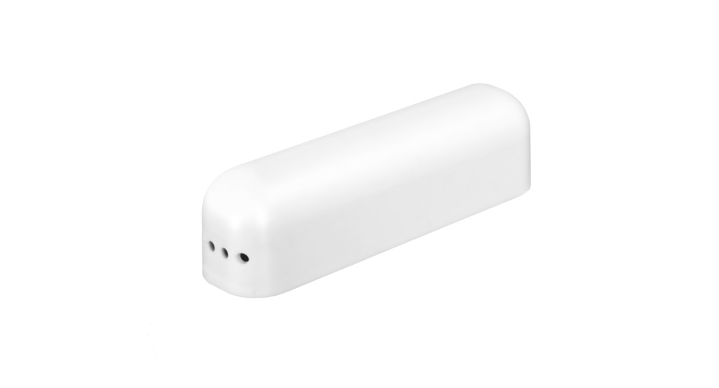
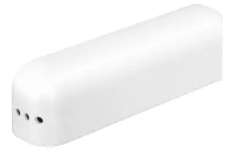
PoppMold detectorSKU: POPE701202

Quickstart
This is a secure Alarm Sensor for Europe. To run this device please insert fresh 1 * 1/2 AA batteries. Please make sure the internal battery is fully charged.Tripple clicking the tamper button includes (adds) and excludes (removes) the device. A click on the tamper witch will wake up the device. The device supports the Security S2 framework with unauthenticated network keys. Please follow the instructions on the central controller when including. The device also supports Smartstart. Please scan the QR code on the outlet cover of the device and your controller will add the device automatically when powered up.
Important safety information
Please read this manual carefully. Failure to follow the recommendations in this manual may be dangerous or may violate the law. The manufacturer, importer, distributor and seller shall not be liable for any loss or damage resulting from failure to comply with the instructions in this manual or any other material. Use this equipment only for its intended purpose. Follow the disposal instructions. Do not dispose of electronic equipment or batteries in a fire or near open heat sources.
What is Z-Wave?
Z-Wave is the international wireless protocol for communication in the Smart Home. This device is suited for use in the region mentioned in the Quickstart seZ-Wave ensures reliable communication by reconfirming every message (two-way communication) and every mains powered node can act as a repeater for other nodes (meshed network) in case the receiver is not in direct wireless range of the transmitter.This device and every other certified Z-Wave device can be used together with any other certified Z-Wave device regardless of brand and origin as long as both are suited for the same frequency range.
If a device supports secure communication it will communicate with other devices secure as long as this device provides the same or a higher level of security. Otherwise, it will automatically turn into a lower level of security to maintain backward compatibility.For more information about Z-Wave technology, devices, white papers, etc. please refer to www.z-wave.info.

Product Description
This device measures the three air quality parameters temperature, humidity, and dew point, and reports them to a central controller. Besides this, the device can dire control groups of other Z-Wave devices on over- and undershooting a set temperature and/or humidity parameter. This can be used to establish control loops for temperature and humidity. The device wakes up every 15 minutes to measure the values and it will send unsolicited reports when values change. Additionally, the device will report all values on request.The mold detector is actively monitoring the danger of mold in a room based on the temperature and humidity and will issue alarm warnings when critical air cond met. Wireless Alarm and red and a green blinking LED will indicate a mold condition. This local LED warning function is also available when the device is not incl in any Z-Wave network and works stand alone.
Prepare for Installation / Reset
Please read the user manual before installing the product.In order to include (add) a Z-Wave device to a network, it must be in the factory default state. Please make sure to reset the device into factory default. You can do by performing an Exclusion operation as described below in the manual. Every Z-Wave controller is able to perform this operation however it is recommended to the primary controller of the previous network to make sure the very device is excluded properly from this network.Reset to factory defaultThis device also allows being reset without any involvement of a Z-Wave controller. This procedure should only be used when the primary controller is inoperable Remove the cover, press the button for 5 seconds until it flashes green. Release the button and press the button again until the blinking stops.
Safety Warning for BatteriesThe product contains batteries. Please remove the batteries when the device is not used. Do not mix batteries of different charging level or different brands.
Installation
The POPP Mold Detector can be mounted in two ways.
- use the enclosed adhesive tape. Clean the substrate carefully from grease and dirt to achieve optimum strength of the adhesive areas.
- use the enclosed screws and dowels to fix it to the wall or other surface.
Inclusion/Exclusion
On factory default, the device does not belong to any Z-Wave network. The device needs to be added to an existing wireless network to communicate devices of this network. This process is called Inclusion.Devices can also be removed from a network. This process is called Exclusion. Both processes are initiated by the primary controller of the Z-Wave new controller is turned into exclusion respective inclusion mode. Inclusion and Exclusion is then performed doing a special manual action right on the device.
Inclusion
- Open the housing.
- Remove the battery protection.
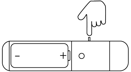
- Press the tamper on the side of the appliance three times quickly.
Exclusion
- Open the housing.
- Press the tamper on the side of the appliance three times quickly.
Product Usage
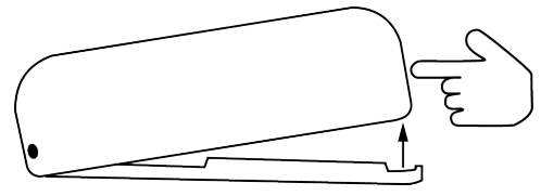
Open the POPP Mold DetectorTo open the POPP Mold Detector, press the lock with your finger and pull the housing cover upwards.
Tamper buttonThe tamper button is located on the side of the POPP Mold Detector. This button is also used for inclusion and exclusion.
Functionality
Once the device is powered up it will start monitoring the air parameters and warn of mold using the local red and green LED. All air parameters are measured in 15 minutes. If there is a change by the value set in parameters 1 and 2, it is sent to the central unit. Pushing the button will force an immediate measurement and LEDs will indicate the danger of mold
- green: no danger of mold in the room
- red: danger of mold, on the windows to lower the humidity
The device contains three sensors with the following accuracy measures:
- Humidity: +/- 3 % on relative humidity, +/-1 % hysteresis
- Temperature: 0 … 65 °C +/- 1 Kelvin
- Dew Point: 0 … 65 °C +/- 1 Kelvin (calculated from other sensor values)
Besides the measured values the device will issue Z-Wave notifications on moisture (0x10).
Node Information Frame
The Node Information Frame (NIF) is the business card of a Z-Wave device. It contains information about the device type and the technical capabilities. The inclined exclusion of the device is confirmed by sending out a Node Information Frame. Besides this, it may be needed for certain network operations to send out an information Frame. To issue a NIF execute the following action: Tripple Click the tamper button
Communication to a Sleeping device (Wakeup)
This device is battery-operated and turned into a deep sleep state most of the time to save battery life. Communication with the device is limited. In order to communicate with the device, a static controller C is needed in the network. This controller will maintain a mailbox for the battery-operated devices and store commands that can not be received during a deep sleep state. Without such a controller, communication may become impossible, and/or the battery life is significantly decreased.This device will wake up regularly and announce the wakeup state by sending out a so-called Wakeup Notification. The controller can then empty the mailbox.Therefore, the device needs to be configured with the desired wakeup interval and the node ID of the controller. If the device was included by a static controller will usually perform all necessary configurations. The wakeup interval is a tradeoff between maximal battery lifetime and the desired responses of thedevice. To wake up the device please perform the following action: A single click on the tamper button will wake up the device.
Quick troubleshooting
Here are a few hints for network installation if things don’t work as expected.
- Make sure a device is in a factory reset state before including it. In doubt exclude before inclu
- If inclusion still fails, check if both devices use the same frequency.
- Remove all dead devices from associations. Otherwise, you will see severe delays.
- Never use sleeping battery devices without a central controller.
- Don’t poll FLIRS devices.
- Make sure to have enough mains powered devices to benefit from the meshing
Association – one device controls another device
Z-Wave devices control other Z-Wave devices. The relationship between one device controlling another device is called association. In order to control the device, the controlling device needs to maintain a list of devices that will receive controlling commands. These lists are called association groups and are related to certain events (e.g. button pressed, sensor triggers, …). In case the event happens all devices stored in the respective association group will same wireless command, typically a ‘Basic Set’ Command.
Association Groups:
| Group Number | Maximum Nodes | Description |
| 1 | 5 | Lifeline |
| 2 | 5 | Temperature High Trigger |
| 3 | 5 | Temperature Low Trigger |
| 4 | 5 | Humidity High Trigger |
| 5 | 5 | Humidity Low Trigger |
Configuration Parameters
Z-Wave products are supposed to work out of the box after inclusion, however, certain configuration can adapt the function better to user needs or unlock further enhanced features.IMPORTANT: Controllers may only allow configuring signed values. In order to set values in the range 128 … 255 the value sent in the application shall be the devalue minus 256. For example: To set a parameter to 200 it may be needed to set a value of 200 minus 256 = minus 56. In the case of a two-byte value, the same log applies: Values greater than 32768 may be needed to be given as negative values too.Parameter 1: Minimum Temperature change to reportThis value defines the minimum change of temperature to cause an unsolicited report of humidity to the central controller using Lifeline.If the value is set to 0, there will be no reports sent to the controller, when the temperature changes. However, periodic reports, managed by configuration para me may still be active.Size: 1 Byte, Default Value: 20
| Setting | Description |
| 1 – 100 | 1/10 degree |
| 0 | disabled |
Parameter 2: Minimum humidity change to report
This value defines the minimum change of humidity to cause an unsolicited report of humidity to the central controller using Lifeline.If the value is set to 0, there will be no reports sent to the controller, when the humidity changes. However, periodic reports, managed by configuration para may still be active.Size: 1 Byte, Default Value: 7
| Setting | Description |
| 1-20 | % |
| 0 | disabled |
Parameter 4: Periodic ReportsThis parameter defines the time interval to send an unsolicited report.If the value is set to 0, there will be no periodic reports sent to the controller. However, reports on temperature/humidity changes, managed by configuration para1 and 2, may still be active.Size: 2 Byte, Default Value: 43200
| Setting | Description |
| 900 – 65535 | Seconds |
| 0 | disabled |
Parameter 5: Temperature Upper Watermark valueThis parameter defines a temperature. If the measured temperature surpasses this watermark a BASIC command is sent into Association Group 2Size: 2 Byte, Default Value: 0
| Setting | Description |
| 1 – 1000 | 1/10 degree |
| 0 | disabled |
Parameter 6: Temperature Lower Watermark valueThis parameter defines a temperature. If the measured temperature drops below this watermark a BASIC command is sent into Association Group 3Size: 2 Byte, Default Value: 0
| Setting | Description |
| 1 – 1000 | 1/10 degree (0,1°C – 100°C) |
| 65336 – 65535 | 1/10 degree (-20,0°C – -0,1°C) |
| 0 | Disable |
Parameter 7: Humidity Upper Watermark valueThis parameter defines relative humidity. If the measured relative humidity surpasses this watermark a BASIC command is sent into Association GroSize: 1 Byte, Default Value: 0
| Setting | Description |
| 10 – 100 | % |
| 0 | disabled |
Parameter 8: Humidity Lower Watermark valueThis parameter defines relative humidity. If the measured temperature drops below this relative humidity a BASIC command is sent into Association GSize: 1 Byte, Default Value: 0
| Setting | Description |
| Jan-90 | % |
| 0 | disabled |
Parameter 9: Low-Temperature Trigger BASIC Set Command ValuThis defines what BASIC command shall be sent out into association group 3Size: 1 Byte, Default Value: 255
| Setting | Description |
| 0 – 255 | Value |
Parameter 10: High-Temperature Trigger BASIC Set Command ValueThis defines what BASIC command shall be sent out into association group 2Size: 1 Byte, Default Value: 0
| Setting | Description |
| 0 – 255 | Value |
Parameter 11: Low Humidity Trigger BASIC Set Command ValueThis defines what BASIC command shall be sent out into association group 5Size: 1 Byte, Default Value: 255
| Setting | Description |
| 0 – 255 | Value |
Parameter 12: High Humidity Trigger BASIC Set Command ValueThis defines what BASIC command shall be sent out into association group 4Size: 1 Byte, Default Value: 0
| Setting | Description |
| 0 – 255 | Value |
Technical Data
| Dimensions | 25x25x10 mm |
| Weight | 11.73 gr |
| Hardware Platform | ZM5101 |
| IAN | 4.25E+12 |
| IP Class | IP 20 |
| Voltage | 3V |
| Battery Type | 1 * 1/2 AA |
| Device Type | Notification Sensor |
| Generic Device Class | Notification Sensor |
| Specific Device Class | Routing Notification Sensor |
| Firmware Version | 1.01 |
| Z-Wave Version | 6.02 |
| Certification ID | ZC10-19026384 |
| Z-Wave Product Id | 0x0154.0x0004.0x0014 |
| Frequency | Europe – 868,4 Mhz |
| Maximum transmission power | 5 mW |
Supported Command Classes
- Basic
- Sensor Binary
- Sensor Multilevel
- Association Grp Info
- Device Reset Locally
- Zwaveplus Info
- Supervision
- Configuration
- Alarm
- Manufacturer Specific
- Powerlevel
- Firmware Update Md
- Battery
- Wake Up
- Association
- Multi-Channel Association
- Version
- Transport Service
- Security 2
Controlled Command Classes
- Transport Service
- Security 2
Explanation of Z-Wave specific terms
- Controller — is a Z-Wave device with capabilities to manage the network. Controllers are typically Gateways, Remote Controls or battery-operated wall controllers.
- Slave — is a Z-Wave device without capabilities to manage the network. Slaves can be sensors, actuators, and even remote controls.
- Primary Controller — is the central organizer of the network. It must be a controller. There can be only one primary controller in a Z-Wave network.
- Inclusion — is the process of adding new Z-Wave devices into a network.
- Exclusion — is the process of removing Z-Wave devices from the network.
- Association — is a control relationship between a controlling device and a controlled device.
- Wakeup Notification — is a special wireless message issued by a Z-Wave device to announces that is able to communicate.
- Node Information Frame — is a special wireless message issued by a Z-Wave device to announce its capabilities and functions.
(c) 2020 Z-Wave Europe GmbH, Antonstr. 3, 09337 Hohenstein-Ernstthal, Germany, All rights reserved, www.zwave.eu. The template is maintained by Z-Wave Europe GmbH. The product content is maintained by Z-Wave Europe GmbH, Support team, [email protected]. Last update of the product data: 2020-02-0413:30:48
 report this ad
http://manual.zwave.eu/backend/make.php?lang=en&sku=POPE701202
References
[xyz-ips snippet=”download-snippet”]