![]() User Manual
User Manual
Flow Stop 2SKU: POPE701479
QuickstartThis is a Powered device for Europe. To run this device please connect it to your mains power supply. For inclusion and exclusion press the red button on the top of the enclosure 3 times. Attention: You must not move the rocker arm manually without unlocking it mechanically pulling on the ring on the bottom side of the enclosure.
Important safety information
Please read this manual carefully. Failure to follow the recommendations in this manual may be dangerous or may violate the law. The manufacturer, importer,distributor, and seller shall not be liable for any loss or damage resulting from failure to comply with the instructions in this manual or any other material. Use thisequipment only for its intended purpose. Follow the disposal instructions. Do not dispose of electronic equipment or batteries in a fire or near open heat sources.
What is Z-Wave?
Z-Wave is the international wireless protocol for communication in the Smart Home. This device is suited for use in the region mentioned in the Quickstart section.Z-Wave ensures reliable communication by reconfirming every message (two-way communication) and every mains-powered node can act as a repeater for other nodes (meshed network) in case the receiver is not in direct wireless range of the transmitter.![]() This device and every other certified Z-Wave device can be used together with any other certified Z-Wave device regardless of brand and origin as long as both are suited for the same frequency range.If a device supports secure communication it will communicate with other devices secure as long as this device provides the same or a higher level of security. Otherwise, it will automatically turn into a lower level of security to maintain backward compatibility.For more information about Z-Wave technology, devices, white papers, etc. please refer to www.z-wave.info.
This device and every other certified Z-Wave device can be used together with any other certified Z-Wave device regardless of brand and origin as long as both are suited for the same frequency range.If a device supports secure communication it will communicate with other devices secure as long as this device provides the same or a higher level of security. Otherwise, it will automatically turn into a lower level of security to maintain backward compatibility.For more information about Z-Wave technology, devices, white papers, etc. please refer to www.z-wave.info.
Product Description
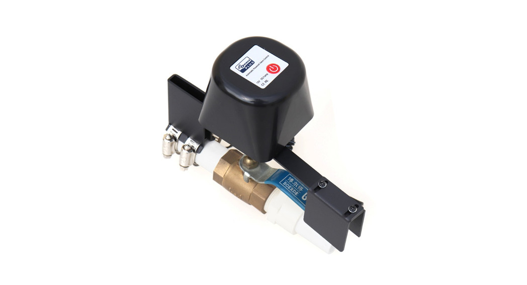
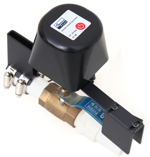
Flow Stop 2 moves the operating handle of a ball valve allowing to stopping the flow of gas or water. It can be mounted non-intrusive on any pipe size between 0.5 and 1.5 inches. This means the original water or gas pipe will not be opened or manipulated and it is possible to remove the Flow stop again without any damage to the water or gas pipe. Installing the Flow stop will not tamper or change any security measure applied or your gas or water installation. The device is equipped with a powerful 12 V motor providing sufficient torque to open or close any ball valve within 10 seconds. A complete manual operation of the valve remains possible due to the clutch release bearing. The device can be operated using the local button and remotely using Z-Wave wireless communication. Various functions protect the flow stop from accidental or intentional misuse:
- Z-Wave Communication applies enhanced security implementing the Security Command Class. This does not only protect the device against burglars that want to do harm to the home (e.g. wastewater by opening the valve to the watering system). It s also protecting better against jamming of the communication link.
- Configuration of the local LED. The user can now decide if the blue LED shall indicate open or close state Unsolicited report of any state change of the flow stop to the controller.
- Second communication channel to report manual operation of the device. Here up to 5 other devices can be operated independent of the controller, e.g. to announce any local operation.
- The remote operation of the device can be limited to no, only open or only close to further protect against malfunction.
Prepare for Installation / Reset
Please read the user manual before installing the product.In order to include (add) a Z-Wave device to a network, it must be in the factory default state. Please make sure to reset the device into factory default. You can do this.
by performing an Exclusion operation as described below in the manual. Every Z-Wave controller is able to perform this operation however it is recommended to use the primary controller of the previous network to make sure the very device is excluded properly from this network.
Reset to factory defaultThis device also allows to be reset without any involvement of a Z-Wave controller. This procedure should only be used when the primary controller is inoperable.Press the button for at least 10 seconds.
Safety Warning for Mains Powered DevicesATTENTION: only authorized technicians under consideration of the country-specific installation guidelines/norms may do works with mains power. Prior to the assembly of the product, the voltage network has to be switched off and ensured against re-switching.
Installation
Use on pipelinesThe main ball valve should be located in an easily accessible place where manual opening and closing are also possible. If the Flow-Flow Stop shut-off motor is installed, it should have a minimum distance of 20mm to the Wall.
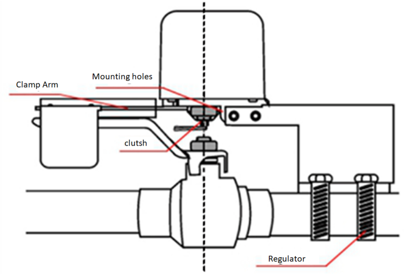
- Mount the Popp Flow Stop 2 on the ball valve using the mounting bracket and the pipe clamps that surround the pipe and fix the motor to the connection hole.
- Fix the mounting bracket using two M6*16 hexagonal screws along the guide rail at both ends of the bracket, but do not over tighten the screws.
- Loosen the screws from the valve arm and position the valve lever to hiss the Veliarm guide. Tighten the screws.
- Adjust the position of the shut-off motor so that it sits straight and parallel on the pipe and the coupling remains freely accessible for the output shaft. Then tighten two M6*16 hexagonal bolts with a 10# open-end or ring spanner (socket spanner recommended).
To integrate the unit into a Z-Wave network (include), press the red function button on the top of the motor housing three times. During inclusion/exclusion, the unit should be within a maximum distance of one meter from the control controller. Before an inclusion/exclusion process, the two screws must be loosened.
For bottled gas userTo connect bottled gas, the user uninstall the original pressure reducing valve and install the manipulator with the special ball valve for pipe between the original angle valve and pressure reducing valve, and then tighten it.
Inclusion/Exclusion
On factory default the device does not belong to any Z-Wave network. The device needs to be added to an existing wireless network to communicate with the devices of this network. This process is called Inclusion.Devices can also be removed from a network. This process is called Exclusion. Both processes are initiated by the primary controller of the Z-Wave network. This controller is turned into exclusion respective inclusion mode. Inclusion and Exclusion is then performed doing a special manual action right on the device.
Inclusion
- Connect the device as described.
- Press the Red button three times in succession.
Exclusion
- Press the red button three times.
Product Usage
The Flow Stop can be operated in three different ways.
- Remotely using Z-Wave wireless on/off commands. The device will appear in your controller as a simple on/off switch easily to operate. To protect the devicefrom tampering or wrongdoing you can limit the remote operations using the configuration parameter #1.
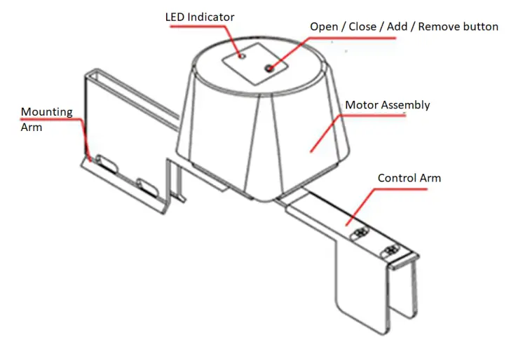
- Local operation by simply pushing the red button. Any push of the button will result in a change of the status from open to close or vice versa.
- Mechanical overwrite allows opening or closing the valve even in case of a power failure. Disconnect the valve using the internal clutch by pulling the ring.Keep the ring pulled while moving the handle manually. Never move the handle without having the clutch disconnected. As best it will not work, in the worst case, it will destroy the device. Operating the valve manually only works without a power supply. If the Flow Stop is powered and you operate the valve the motor will drive it into the previous position immediately.
Node Information Frame
The Node Information Frame (NIF) is the business card of a Z-Wave device. It contains information about the device type and the technical capabilities. The inclusion and exclusion of the device is confirmed by sending out a Node Information Frame. Beside this it may be needed for certain network operations to send out a Node Information Frame. To issue a NIF execute the following action: Press the red inclusion button 3 times
Quick troubleshooting
Here are a few hints for network installation if things dont work as expected.
- Make sure a device is in a factory reset state before including. In doubt exclude before include.
- If inclusion still fails, check if both devices use the same frequency.
- Remove all dead devices from associations. Otherwise, you will see severe delays.
- Never use sleeping battery devices without a central controller.
- Dont poll FLIRS devices.
- Make sure to have enough mains powered devices to benefit from the meshing
Association – one device controls another device
Z-Wave devices control other Z-Wave devices. The relationship between one device controlling another device is called association. In order to control a different device, the controlling device needs to maintain a list of devices that will receive controlling commands. These lists are called association groups and they are always related to certain events (e.g. button pressed, sensor triggers, …). In case the event happens all devices stored in the respective association group will receive the same wireless command, typically a ‘Basic Set’ Command.
 report this ad
Association Groups:
| Group Number | Maximum Nodes | Description |
| 1 | 1 | Lifeline |
Technical Data
| Dimensions | 195 x 120 x 74 mm |
| Weight | 608 gr |
| Hardware Platform | ZM5101 |
| EAN | 4.25E+12 |
| IP Class | IP 64 |
| Device Type | Powered device |
| Generic Device Class | Switch Binary |
| Specific Device Class | Binary Power Switch |
| Z-Wave Version | 4.54.02 |
| Certification ID | ZC08-14030002 |
| Z-Wave Product Id | 0x0154.0x0005.0x0003 |
| Frequency | Europe – 868,4 Mhz |
| Maximum transmission power | 5 mW |
Supported Command Classes
- Switch All
- Basic
- Manufacturer Specific
- Switch Binary
- Version
Explanation of Z-Wave specific terms
- Controller — is a Z-Wave device with capabilities to manage the network. Controllers are typically Gateways, Remote Controls, or battery-operated wall controllers.
- Slave — is a Z-Wave device without capabilities to manage the network. Slaves can be sensors, actuators, and even remote controls.
- Primary Controller — is the central organizer of the network. It must be a controller. There can be only one primary controller in a Z-Wave network.
- Inclusion — is the process of adding new Z-Wave devices into a network.
- Exclusion — is the process of removing Z-Wave devices from the network.
- Association — is a control relationship between a controlling device and a controlled device.
- Wakeup Notification — is a special wireless message issued by a Z-Wave device to announces that is able to communicate.
- Node Information Frame — is a special wireless message issued by a Z-Wave device to announce its capabilities and functions.
(c) 2020 Z-Wave Europe GmbH, Antonstr. 3, 09337 Hohenstein-Ernstthal, Germany, All rights reserved, www.zwave.eu. The template is maintained by Z-Wave Europe GmbH. The product content is maintained by Z-Wave Europe GmbH, Supportteam, [email protected]. Last update of the product data: 2020-06-25
http://manual.zwave.eu/backend/make.php?lang=en&sku=POPE701479
References
[xyz-ips snippet=”download-snippet”]