
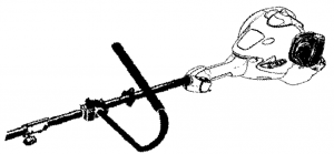
POULAN PRO RS25CCPR/RS25CSPR Gas Grass Trimmer Instruction Manual
OPTIONAL ATTACHMENT
These attachments used in combination with the specified powerhead have been evaluated to ANSI B175.3 –2013, “Grass Trimmers and Brushcutters – Safety Requirements.
|
Powerhead model |
Attachments |
Type |
Cutting attachment / guard part no. |
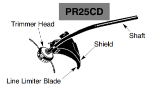
| PR25CD | Trimmer head | TNG 7 | 537419223 / 530071802 |
|
Powerhead model |
Attachments | Type |
Cutting attachment / guard part no. |
| PR25SD | Trimmer head | TNG 7 | 537419211 / 585345917 |
SAFETY RULES
![]() WARNNIG: When using gardening appliances, basic safety precautions must al- ways be followed to reduce the risk of fire and serious injury. Read and follow all instructions. Operator is responsible for following instruc- tions and warnings on unit and in manual. Read entire instruction manual before using unit! Be thoroughly familiar with the controls and the proper use of the unit. Restrict the use of this unit to persons who have read, under- stand, and will follow the instructions and warnings on the unit and in the manual. Never allow children to operate this unit.
WARNNIG: When using gardening appliances, basic safety precautions must al- ways be followed to reduce the risk of fire and serious injury. Read and follow all instructions. Operator is responsible for following instruc- tions and warnings on unit and in manual. Read entire instruction manual before using unit! Be thoroughly familiar with the controls and the proper use of the unit. Restrict the use of this unit to persons who have read, under- stand, and will follow the instructions and warnings on the unit and in the manual. Never allow children to operate this unit.
 Instruction Manual
 Safety Information
![]() WARNNIG:
WARNNIG:
Never use blades with line trimmer attachment. Never use flailing de- vices with any attachment. This unit (when used with supplied line trimmer attachment) is de- signed for line trimmer use only. Use of any oth- er accessories or attachments with line trimmer attachment will increase the risk of injury.
If situations occur which are not covered in this manual, use care and good judgment. If you need assistance, contact your authorized service dealer or call 1-800-554 -6723.
OPERATOR SAFETY
- Dress properly. Always wear safety glasses or similar eye protection when operating, or performing maintenance, on your unit (safety glasses are available). Eye protection should be marked.
- Always wear hearing
- Always wear face or dust mask if operation is dusty.
- Always wear heavy, long pants, long sleeves, boots, and gloves. Wearing safety leg guards is recommended.
- Always wear foot protection. Do not go barefoot or wear sandals. Stay clear of spinning line.
- Secure hair above shoulder Secure or remove loose clothing or clothing with loosely hanging ties, straps, tassels, etc. They can be caught in moving parts.
- Being fully covered also helps protect you from debris and pieces of toxic plants thrown by spinning
- Stay alert. Do not operate this unit when you are tired, ill, upset or under the influence of alcohol, drugs, or medication. Watch what you are doing; use common
- Never start or run inside a closed room or building. Breathing exhaust fumes can kill, Keep handles free of oil and fuel.
- Keep handles free of oil and tuel.
- Always keep engine on the right hand side of your body.
- Hold the unit firmly with both.
- Keep trimmer head (or other optional attachment) below waist level and away from all parts of your body.
- Keep all parts of your body away from muffler and spinning line (or other optional attachment). Keep engine below waist level. A hot muffler can cause serious burns.
- Keep firm footing and balance. Do not overreach or use from unstable surfaces such as ladders, trees, steep slopes, rooftops, etc.
- Use only in daylight or good artificial light.
- Use only for jobs explained in this manual (or manuals for optional attachments).
UNIT / MAINTENANCE SAFETY
- Disconnect the spark plug before performing maintenance except idle speed adjustment.
- Look for and replace damaged or loose parts before each Look for and repair fuel leaks before use. Keep in good working condition.
- Replace trimmer head parts that are chipped, cracked, broken, or damaged in any other way before using the unit.
- Maintain unit according to recommended Keep cutting line at proper length.
- Use only 095 in. (2.4 mm) diameter Poulan PRO brand line. Never use wire, rope, string, etc.
- Install required shield properly before using the unit. Use only specified trimmer head; make sure it is properly installed and securely
- Make sure unit is assembled correctly as shown in this manual.
- Make idle speed adjustments with lower end supported to prevent line from contacting any objects.
- Keep others away when making idle speed adjustment.
- Use only recommended Poulan PRO accessories and replacement parts.
- Have all maintenance and service not explained in this manual performed by an authorized service dealer.
FUEL SAFETY
- Mix and pour fuel outdoors.
- Keep away from sparks or flames.
- Use a container approved for fuel.
- Do not smoke or allow smoking near fuel or the unit.
- Avoid spilling fuel or Wipe up all fuel spills.
- Move at least 10 feet (3 meters) away from fueling site before starting engine.
- Stop engine and allow to cool before removing fuel cap.
- Always store gasoline in a container approved for flammable liquids.
TRANSPORTING AND STORAGE
- Allow engine to cool; secure unit before storing or transporting in vehicle.
- Empty the fuel tank before storing or transporting the Use up fuel left in the carburetor by starting the engine and letting it run until it stops.
- Store unit and fuel in area where fuel vapors cannot reach sparks or open flames from water heaters, electric motors or switches, furnaces, etc.
- Store unit so line limiter blade cannot accidentally cause injury. The unit can be hung by the shaft.
- Store unit out of reach of children.
SAFETY NOTICE: Exposure to vibrations through prolonged use of gasoline powered hand tools could cause blood vessel or nerve damage in the fingers, hands, and joints of people prone to circulation disorders or abnormal Prolonged use in cold weather has been linked to blood vessel damage in otherwise healthy people. If symptoms occur such as numbness, pain, loss of strength, change in skin color or texture, or loss of feeling in the fingers, hands, or joints, discontinue the use of this tool and seek medical attention. An anti-vibration system does not guarantee the avoidance of these problems. Users who operate power tools on a continual and regular basis must monitor closely their physical condition and the condition of this tool.
SPECIAL NOTICE:
This unit is equipped with a temperature limiting muffler and spark ar-resting screen which meets the requirements of California Codes 4-442 and 4443. All U.S. forest land and the states of California, Idaho, Maine, Minnesota, New Jersey, Oregon, and Washing-ton require by law that many internal combustion engines be equipped with a spark arresting screen. If you operate in a locale where such regulations exist, you are legally responsible for maintaining the operating condition of these parts. Failure to do so is a violation of the law. For normal homeowner use, the muffler and spark arresting screen will not require any service. After 50 hours of use, we recommend that your muffler be serviced or replaced by your authorized service dealer.
LINE TRIMMER SAFETY AWARNING:
![]() WARNNIG: Inspect area before starting unit. Remove all debris and hard ob-jects such as rocks, glass, wire, etc., that can ricochet, be thrown, or otherwise cause injury or damage during operation.
WARNNIG: Inspect area before starting unit. Remove all debris and hard ob-jects such as rocks, glass, wire, etc., that can ricochet, be thrown, or otherwise cause injury or damage during operation.
- Use only for trimming, scalping, mowing and sweeping. Do not use for edging, pruning or hedge trimming.
- Cut from your left to your right. Cutting on right side of the shield will throw debris away from the operator.
ADDITIONAL SAFETY RULES FOR OPTIONAL ATTACHMENTS A WARNING:
![]() WARNNIG: For each optional attachment used, read entire instruction manual before use and follow all warnings and instructions in manual and on attachment. A
WARNNIG: For each optional attachment used, read entire instruction manual before use and follow all warnings and instructions in manual and on attachment. A
![]() WARNNIG: Ensure handlebar is installed when using brush cutter attachment. Attach handlebar above arrow on safety label on the upper shaft (engine end of unit). If your brush cutter attachment does not include a handlebar, a handlebar accessory kit (#530071451) is available from your authorized service dealer.
WARNNIG: Ensure handlebar is installed when using brush cutter attachment. Attach handlebar above arrow on safety label on the upper shaft (engine end of unit). If your brush cutter attachment does not include a handlebar, a handlebar accessory kit (#530071451) is available from your authorized service dealer.
 HANDLEBAR
ASSEMBLY
CAUTION: If received asserted, repeat all steps to ensure your unit is properly assembled and all fasteners are secure. Examine parts for damage. Do not use darn-aged parts.
NOTE: If you need assistance or find parts missing or damaged, call 1-800-5546723. It is normal for the fuel fitter to rattle in the empty fuel tank.Finding fuel or oil residue on muffler is normal due to carburetor adjustments and testing done by the manufacturer.
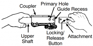
INSTALLING TRIMMER ATTACH-MENT
CAUTION: When installing trimmer attachment, place the unit on a flat surface for stability.

- Loosen the coupler by turning the knob counterclockwise.
- Remove shipping protector from coupler.
- Remove the shaft cap from the trimmer attachment (d present).
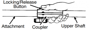
- Position locking/release button of attachment into guide recess of coupler.
- Push the attachment into the coupler until the locking/release button snaps into the primary hole.
- Before using the unit, lighten the knob securely by tuning clockwise.
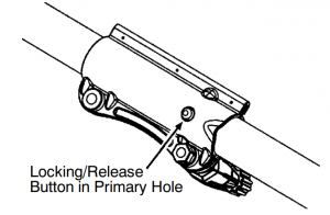
![]() WARNNIG: Make sure the locking release button is locked in the primary hole and the knob is securely tightened before operating the unit All attachments are designed to be used in the primary hole unless otherwise stated in the applicable attachment instruction manual. Using the wrong hole could lead to serials injury or damage to the unit
WARNNIG: Make sure the locking release button is locked in the primary hole and the knob is securely tightened before operating the unit All attachments are designed to be used in the primary hole unless otherwise stated in the applicable attachment instruction manual. Using the wrong hole could lead to serials injury or damage to the unit
For assembly of optional attachments, refer to the ASSEMBLY section of the applicable attachment instruction manual.
ATTACHING THE SHIELD
CAUTION: The shield must be property installed. The shield provides partial protection from the risk of thrown objects to the operator and others and is equipped with a line limiter blade which cuts excess line to the proper length. The line limiter blade (on underside of shield) 4 sharp and can cut you.
For proper orientation of shield, see KNOW YOUR TRIMMER illustration in OPERATION section.
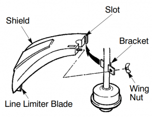
- Remove wing nut from shield.
- Insert bracket into slot as shown.
- Pivot shield until bolt passes through hole in bracket.
- Securely tighten wing nut onto bolt.
ADJUSTING THE HANDLE CAUTION:
When adjusting the handle, be sure it remains above the safety label and be-low the mark or arrow on the shaft.
- Loosen wing nut on handle.
- Rotate the handle on the shaft to an up-right position; retighten wing nut.
OPRATION
KNOW YOUR UNIT
READ This INSTRUCTION MANUAL AND SAFETY RULES BEFORE OPERATING YOUR UNIT. Compare the illustrations with your unit to familiarize yourself with the location of the various controls and adjustments. Save this manual for future reference.
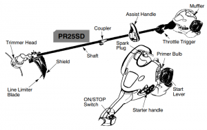
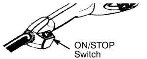
ON/STOP SWITCHThe ON/STOP switch is located on the trigger handle and is used to stop the engine. To stop the engite. push and release the engine ON/STOP switch.
PRIMER BULBThe PRIMER BULB removes air from the car-buretor and fuel lines and fills them with fuel. This allows you to start the engine with fewer pulls on the starter rope. Activate the primer bulb by pressing it and allowing it to return to its original form.
START LEVER
The START LEVER helps to supply fuel to the engine to aid in starling. Activate the starting system by _moving the start lever to the START position. DO NOT squeeze the throttle trigger until the engine has started and runs. After the engine starts, allow the engine to warm-up 10-15 seconds, then fully squeeze the throttle trigger to deactivate the starling system.
COUPLERThe COUPLER enables optional attach-ments to be installed on the unit.
BEFORE STARTING ENGINE A WARNING:
![]() WARNNIG: Be sure to read the filet information in the safety rules before you be-gin. If you do not understand the safety rules. do not attempt to fuel your unit. cam 1-800-554-6723.
WARNNIG: Be sure to read the filet information in the safety rules before you be-gin. If you do not understand the safety rules. do not attempt to fuel your unit. cam 1-800-554-6723.
FUELING ENGINE
![]() WARNNIG: Remove fuel cap slowly when refueling.
WARNNIG: Remove fuel cap slowly when refueling.
 HELPFUL TIPTo obtain the correct oil mix ratio, pour 26 ounces of 2-cycle synthetic oil Ito one gallon of fresh gas.
IMPORTANT: This equipment is designed to operate on unleaded gasoline with a minimum 87 octane (R+M/2 method), with ethanol blended up to 10% maximum by volume (E-10). Be-fore operation, gasoline must be mixed with a good quality synthetic 2-cycle air-cooled engine oil designed to be mixed at a ratio of 50:1. Poulan/WEED EATER brand synthetic oil is re-commended. Mix gasoline and oil at a ratio of 50:1. A 50:1 ratio is obtained by mixing 2.6 fluid ounces of oil with 1 gallon of unleaded gasoline. DO NOT USE automotive oil or marine oil. These oils will cause engine damage. When mixing fuel, follow instructions printed on container. Once oil is added to gasoline, shake container momentarily to assure that the fuel is thoroughly mixed. Always read and follow the safety rules relating to fuel before fueling your unit. Purchase fuel in quantities that can be used within 30 days to assure fuel freshness.
CAUTION: Never use straight gasoline in your unit. This will cause permanent engine damage and void the limited warranty. Do not use alternate fuels such as ethanol blends above 10% by volume (E-15, E-85) or any methanol blended fuel. Use of these fuels can cause major engine performance and durability problems.
HOW TO STOP YOUR UNIT
- Release the throttle trigger.
- Push and release the engine ON/STOP switch. The switch will automatically return to the ON position. Wait 5 seconds before at-tempting to restart unit to allow switch to reset.

HOW TO START YOUR UNIT
![]() WARNNIG: Avoid any contact v4th the muffler. A hot muffler can cause serious burns.
WARNNIG: Avoid any contact v4th the muffler. A hot muffler can cause serious burns.

 HELPFUL TIPIf your engine still does not in start after following these instructions. please call 1-800-554-6723.
STARTING A COLD ENGINENOTE: DO NOT squeeze the throttle inner until the engine has started and runs.
- Set unit on a flat surface.
- Sexy press the primer bit 6 time.
- Mlove the start lever to the START position.
- Pull starter rope handle sharply until engine starts and runs.NOTE: If the engine does not start. it is probably flooded. Refer to STARTING A FLOODED ENGINE in this section.
- Allow unit to runs for 10-15 seconds. then fully squeeze the throttle trigger to disengage the starting system.
 NOTE: If the engine does not start. it is probably flooded. Refer to STARTING A FLOODED ENGINE in this section.
STARTING A WARM ENGINE
- Squeeze and hold the throttle trigger. Keep throttle trigger fully squeezed until engine runs smoothly.
- Pull starter rope sharply while squeezing throttle trigger until engine.NOTE: Normally the warm starting procedure can be used within 5-10 minutes after the Intl is turned off. If the unit sits for more than 10 minutes without being ran, it will be necessary to start the unit by following the steps under STARTING COLD ENGINE or following the stetting instruction steps shown on the unit.
STARTING A FLOODED ENGINEFlooded engines can be started by placing the start lever to the RUN position. Fully squeeze throttle trigger. Pull the starter handle repeatedly while squeezing throttle trigger.
until engine starts and runs. This could re-quire pulling the starter handle many times, depending on how badly the unit is flooded. If the unit still doesn’t start, refer to TROUBLESHOOTING TABLE or call 1-800-554-6723.
OPERATING THE COUPLER
This model is equipped with a coupler which enables optional attachments to be installed. The optional attachments are:MODEL:Edger……………………..PP1000ECultivator………………..PP2000TBlower…………………….PP3000BBrushcutter……………..PP4000CPruner…………………….PP5000PHedge Trimmer……….PP6000H
![]() WARNNIG: Always stop unit and disconnect spark plug before removing or instal-ling attachments.REMOVING TRIMMER ATTACH-MENT (OR OTHER OPTIONAL ATTACHMENTS)CAUTION: When removing or installing attachments, place the unit on a flat surface for stability.
WARNNIG: Always stop unit and disconnect spark plug before removing or instal-ling attachments.REMOVING TRIMMER ATTACH-MENT (OR OTHER OPTIONAL ATTACHMENTS)CAUTION: When removing or installing attachments, place the unit on a flat surface for stability.
- Loosen the coupler by turning the knob counterclockwise.
- press and hold the locking released button.
- While securely holding the engine and upper shaft, pull the attachment straight out of the coupler.

INSTALLING OPTIONAL ATTACH-MENTS
- Remove the shaft cap from the attachment (if present).
- Position locking/release button of attachment into guide recess of coupler.
- Push the attachment into the coupler until the locking/release button snaps into the primary hole.
- Before using the unit, tighten the knob securely by turning clockwise.

![]() WARNNIG: Make sure the locking/ release button is locked in the primary hole and the knob is securely tightened before operating the unit. All attachments are designed to be used in the primary hole unless otherwise stated in the applicable attachment instruction manual Using the wrong hole could lead to serious injury or damage to the unit.
WARNNIG: Make sure the locking/ release button is locked in the primary hole and the knob is securely tightened before operating the unit. All attachments are designed to be used in the primary hole unless otherwise stated in the applicable attachment instruction manual Using the wrong hole could lead to serious injury or damage to the unit.
Locking/Release Button in Primary Hole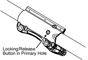
OPERATING INSTRUCTIONS
It is recommended that the engine not be operated for longer than 1 minute at full throttle.
OPERATING POSITION

![]() WARNNIG: Always wear eye protection. Never lean over the trimmer head. Rocks or debris can ricochet or be thrown into eyes and face and cause blindness or other serious injury. When operating unit, stand as shown and check for the following:
WARNNIG: Always wear eye protection. Never lean over the trimmer head. Rocks or debris can ricochet or be thrown into eyes and face and cause blindness or other serious injury. When operating unit, stand as shown and check for the following:
- Wear eye protection and heavy clothing.
- Hold trigger handle with your right hand and assist handle with left hand. • Keep unit below waist level.
- PR25CD: Cut only from your right to your left to ensure debris is thrown away from you.
- PR25SD: Cut only from your left to your right to ensure debris is thrown away from you.
- Without bending over, keep line near and parallel to the ground and not crowded into material being cut.
Do not run the engine at a higher speed than necessary. The cutting line will cut efficiently when the engine is run at less than full throttle. At lower speeds, there is less engine noise and vibration. The cutting line will last longer and will be less likely to “weld’ onto the spool. Always release the throttle trigger and allow the engine to return to idle speed when not cutting. To stop engine:
- Release the throttle trigger.
- Push and release the engine ON/STOP switch.
TRIMMER LINE ADVANCE
The trimmer line will advance approximately 2 inches (5 cm) each time the bottom of the trimmer head is tapped on the ground with the engine running at full throttle. The most efficient line length is the maximum length allowed by the line limiter. Always keep the shield in place when the tool is being operated.
To advance line:
- Operate the engine at full throttle.
- Hold the trimmer head parallel to and above the grassy area.
- Tap the bottom of the trimmer head lightly on the ground one time. Approximately 2 inches (5 cm) of ine will be advanced with each tap.Always tap the trimmer head on a grassy area. Tapping on surfaces such as concrete or as phalt can cause excessive wear to the trimmer head. lf the line is worn down to 2 inches (5 cm) or less, more than one tap will be required to obtain the most efficient line length. WARNNIG:Use only 0.095 in. (2.4 mm) diameter line. Other sizes of line will not advance properly and can cause serious injury. Do not use other materials such as wire, string, rope, etc. Wire can break off dur-ing cutting and become a dangerous pro-jectile that can cause serious injury.
CUTTING METHODS
![]() WARNNIG: Use minimum speed and do not crowd the line when cutting around hard objects (rock, gravel, fence posts, etc.), which can damage the trimmer head, become entangled in the line, or be thrown causing a serious hazard.
WARNNIG: Use minimum speed and do not crowd the line when cutting around hard objects (rock, gravel, fence posts, etc.), which can damage the trimmer head, become entangled in the line, or be thrown causing a serious hazard.
- The tip of the line does the cutting. You will achieve the best performance and mini-mum line wear by not crowding the line into the cutting area. The right and wrong ways are shown below. Tip of the line Line crowded into does the cutting. work area.
- The line will easily remove grass and weeds from around walls, fences, trees and flower beds, but it also can cut the tender bark of trees or shrubs and scar fences.
- For trimming or scalping, use less than full throttle to increase line life and decrease head wear, especially:
- During light duty cutting.
- Near objects around which the line can wrap such as small posts, trees or fence wire.
- For mowing or sweeping, use full throttle for a good clean job.


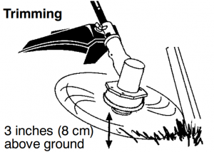
TRIMMING – Hold the bottom of the trimmer head about 3 inches (8 cm) above the ground and at an angle. Mow only the tip of the line to make contact. Do not force trimmer line into work area.
SCALPING – The scalping technique removes unwanted vegetation down to the ground. Hold the bottom of the trimmer head about 3 in. (8 cm) above the ground and at an angle. Mow the tip of the line to strike the ground around trees, posts, monuments, etc. This technique in-creases line wear.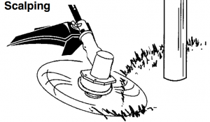
MOWING – Your trimmer is ideal for mowing in places conventional lawn mowers cannot reach. In the mowing position, keep the line parallel to the ground. Avoid pressing the head into the ground as this can scalp the ground and damage the tool.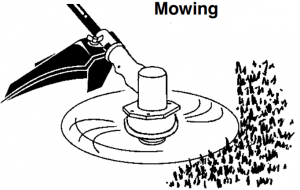
SWEEPING – The fanning action of the rotating line can be used to blow away loose debris from an area. Keep the line parallel to and above the area surface and swing the tool from side to side.
MAITENANCE
![]() WARNNIG: Disconnect the spark plug before performing maintenance except or idle speed adjustments.
WARNNIG: Disconnect the spark plug before performing maintenance except or idle speed adjustments.
 HELPFUL TIPIMPORTANT: Have all 4711) repairs other than the recommended maintenance described in the instruction manual performed by an authorized service dealer. If any dealer other than an authorized service dealer performs work on the product, Poulan PRO may not pay for repairs under warranty. It is your responsibility to maintain and perform general maintenance.CHECK FOR LOOSEFASTENERS AND PARTS
- Spark Plug Boot
- Air Filter
- Housing Screws
- Assist Handle Screw
- Debris ShieldCHECK FOR DAMAGED OR WORN PARTSContact an authorized service dealer for re-placement of damaged or worn parts.
- ON/STOP Switch – Ensure ON/STOP switch functions properly by pushing and releasing the switch. Make sure engine stops. Wait 5 seconds before attempting to restart unit to allow switch to reset. Restart engine and continue.
- Fuel Tank – Discontinue use of unit if fuel tank shows signs of damage or leaks.
- Debris Shield – Discontinue use of unit if debris shield is damaged.INSPECT AND CLEAN UNIT AND DE-CALS
- After each use, inspect complete unit for loose or damaged parts. Clean the unit and decals using a damp cloth with a mild deter-gent. • Wipe off unit with a clean dry cloth.
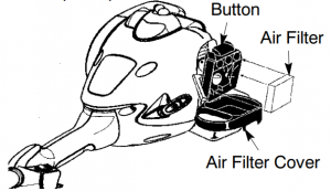
CLEAN AIR FILTERA dirty air filter decreases engine performance and increases fuel consumption and harmful emissions. Always clean after every 5 hours of operation.
- Clean the cover and the area around it to keep dirt from falling into the carburetor chamber when the cover is removed.
- Remove parts by pressing button to re-lease air filter cover.NOTE: To avoid creating a fire hazard or producing harmful evaporative emissions, do not clean filter in gasoline or other flammable solvent.
- Wash the filter in soap and water.
- Allow filter to dry. 5. Replace parts.
INSPECT MUFFLER AND SPARK ARRESTING SCREENAs your unit is used, carbon deposits build up on the muffler and spark arresting screen and must be removed to avoid creating a fire hazard or affecting engine performance.For normal homeowner use, the muffler and spark arresting screen will not require any service. After 50 hours of use, we recommend that your muffler be serviced or re-placed by an authorized service dealer.REPLACE SPARK PLUGReplace the spark plug each year to ensure the engine starts easier and runs better. Set spark plug gap at 0.025 inch (0.6 mm). Ignition timing is fixed and nonadjustable.NOTE: This spark ignition system complies with the Canadian standard ICES-002.
SERVICE AND ADJUSTMENT
REPLACING THE LINE
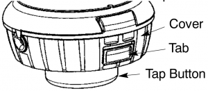
- Press the tabs on the side of the trimmer head and remove cover and spool.
- Remove any remaining line.
- Clean dirt and debris from all Re- place spool if it is worn or damaged.
- Replace with a pre-wound spool, or re- place line using a 15 feet (4.5 meters) length of 0.095 in. (2.4 mm) diameter Poulan PRO brand line. WARNNIG: Never use wire, rope, string, etc., which can break off and become a dangerous projectile. Never use wire, rope, string, etc., which can break off and become a dangerous projectile.
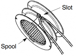
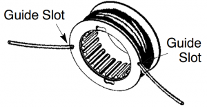
- When installing new line on an existing spool, hold the spool as shown in the il- lustration below.
- Bend the line at the midpoint and insert the bend into the slot in the center rim of the spool. Ensure line snaps into position in the slot.
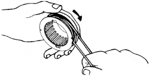
- With your finger between the lines, wrap the lines evenly and firmly around the spool in a clockwise direction.
- Position the lines in the guide slots.
- Insert the ends of the lines through exit holes in the sides of the cover.
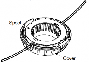
- lace the spool in the cover.
- Make sure the lines are not caught be- tween the rim of the spool and the wall of the cover.
- Reinstall the spool and cover onto the trimmer Push until cover snaps into place.
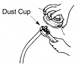
REPLACING THE TRIMMER HEAD (PR25CD)
- Hold the dust cup with a wrench to keep the shaft from turning while removing and installing trimmer. head.
- Remove trimmer head by turning counter- clockwise (looking from bottom of unit).
- Thread replacement trimmer head onto the shaft by turning clockwise. Only tighten hand tight!
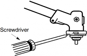
REPLACING THE CUTTING HEAD (PR25SD)
- Align hole in the dust cup with the hole in the side of the gearbox by rotating the dust cup.
- Insert a small screwdriver into aligned This will keep the shaft from turning while removing and installing trimmer head.
- While holding the screwdriver in position, remove trimmer head by turning clockwise.
- Thread replacement trimmer head onto the shaft by turning counterclockwise. Tighten until secure.
- Remove the screwdriver.
IDLE SPEED ADJUSTMENT
![]() WARNNIG: Keep others away when making idle speed adjustments. The trimmer head, blade or any optional attachment will be spinning during most of this procedure. Wear your protective equipment and observe all safe- ty precautions. After making adjustments, the trimmer head, blade or any optional attachment must not move/spin at idle speed.The carburetor has been carefully set at the factory. Adjustment of the idle speed may be necessary if you notice any of the following conditions:
WARNNIG: Keep others away when making idle speed adjustments. The trimmer head, blade or any optional attachment will be spinning during most of this procedure. Wear your protective equipment and observe all safe- ty precautions. After making adjustments, the trimmer head, blade or any optional attachment must not move/spin at idle speed.The carburetor has been carefully set at the factory. Adjustment of the idle speed may be necessary if you notice any of the following conditions:
- Engine will not idle when the throttle is released.
- The trimmer head, blade or optional attachment moves/spins at idle.Make adjustments with the unit supported so the cutting attachment is off the ground and will not make contact with any object. Hold the unit by hand while running and making adjustments. Keep all parts of your body away from the cutting attachment and muffler.
To adjust idle speed:Allow engine to idle. Adjust speed until engine runs without trimmer head, blade or optional attachment moving or spinning (idle too fast) or stalling (idle speed too slow).
- Turn idle speed screw clockwise to increase engine speed if engine stalls or dies.
- Turn idle speed screw counterclockwise to decrease engine speed if trimmer head, blade or optional attachment moves or spins at idle. WARNNIG: Recheck the idle speed after each adjustment. The trimmer head, blade or optional attachment must not move or spin at idle speed to avoid serious injury to the operator or others.If you require further assistance or are unsure about performing this procedure, contact an authorized service dealer or call 1 -800 -554 -6723.
 If you require further assistance or are unsure about performing this procedure, contact an authorized service dealer or call 1 -800 -554 -6723.
STORAGE
CAUTION: Perform the following steps af- ter each use:
- Allow engine to cool before storing or transporting.
- Store unit and fuel in a well ventilated area where fuel vapors cannot reach sparks or open flames from water heaters, electric motors or switches, furnaces, etc.
- Store unit with all guards in Position unit so that any sharp object cannot acci- dentally cause injury.
- Store unit and fuel well out of the reach of children.
SEASONAL STORAGE
Prepare unit for storage at end of season or if it will not be used for 30 days or more. If your unit is to be stored for a period of time:
- Clean the entire unit before lengthy storage.
- Store in a clean dry area.
- Lightly oil external metal surface.
FUEL SYSTEMUnder FUELING ENGINE in the OPERA- TION section of this manual, see message labeled IMPORTANT regarding the use of proper fuel in your engine.Fuel stabilizer is an acceptable alternative in minimizing the formation of fuel gum deposits during storage. Add stabilizer to the gasoline in the fuel tank or fuel storage container. Follow the mix instructions found on stabilizer container. Run engine at least 5 minutes after adding stabilizer.
 HELPFUL TIPDuring storage of your gas/ oil mixture, the oil will sepa- rate from the gas. We recommend that you shake the gas can weekly to insure proper blending of the gas and oil.
ENGINE
- Remove spark plug and pour 1 teaspoon of 50:1, 2-cycle engine oil (air cooled) through the spark plug opening. Slowly pull the starter rope 8 to 10 times to distribute oil.
- Replace spark plug with new one of recom- mended type and heat range.
- Clean air filter.
- Check entire unit for loose screws, nuts, and Replace any damaged, broken, or worn parts.
- At the beginning of the next season, use only fresh fuel having the proper gasoline to oil ratio.OTHER
- Do not store gasoline from one season to another.
- Replace your gasoline can if it starts to rust.
TROUBLESHOOTING TABLE
![]() WARNNIG: Always stop unit and disconnect spark plug before performing all of the recommended remedies below except remedies that require operation of the unit.
WARNNIG: Always stop unit and disconnect spark plug before performing all of the recommended remedies below except remedies that require operation of the unit.
| TROUBLE | CAUSE |
REMEDY |
|
Engine will not start. |
|
|
|
Engine will not idle properly. |
|
|
|
Engine will not accelerate, lacks power, or dies under a load. |
|
|
|
Engine smokes excessively. |
|
|
|
Engine runs hot. |
|
|
U.S. EPA / CALIFORNIA / ENVIRONMENT CANADA EMISSION CONTROL WARRANTY STATEMENT
IMPORTANT: This product is compliant with U.S. EPA Phase 3 regulations for exhaust and evaporative emissions. To ensure EPA Phase 3 compliance, we recommend using only genuine replacement parts. Use of non-compliant replacement parts is a violation of federal law.
YOUR WARRANTY RIGHTS AND OBLIGATIONS: The U.S. Environmental Protection Agency, California Air Resources Board, Environment Canada and Husqvarna Consumer Outdoor Products N.A., Inc. are pleased to explain the emissions control system warranty on your year 2016 and later off-road engine. In California, all small off-road engines must be designed, built, and equipped to meet the State’s stringent anti-smog standards. Husqvarna Consumer Outdoor Products N.A., Inc. must warrant the emission control system on your small off-road engine for the periods of time listed below provided there has been no abuse, neglect, or improper maintenance of your small off-road engine. Your emission control system includes parts such as the carburetor, the ignition system and the fuel tank, line, and cap. Where a warrantable condition exists, Husqvarna Consumer Outdoor Products N.A., Inc. will repair your small off-road engine at no cost to you. Expenses covered under warranty include diagnosis, parts and labor.
MANUFACTURER’S WARRANTY COVERAGE: If any emissions related part on your engine (as listed under Emissions Control Warranty Parts List) is defective or a defect in the materials or workmanship of the engine causes the failure of such an emission related part, the part will be repaired or replaced by Husqvarna Consumer Outdoor Products N.A., Inc..
OWNER’S WARRANTY RESPONSIBILITIES: As the small off-road engine owner, you are responsible for the performance of the required maintenance listed in your instruction manual. Husqvarna Consumer Outdoor Products N.A., Inc. recommends that you retain all receipts covering maintenance on your small off-road engine, but Husqvarna Consumer Outdoor Products N.A., Inc. cannot deny warranty solely for the lack of receipts or for your failure to ensure the performance of all scheduled maintenance. As the small off-road engine owner, you should be aware that Husqvarna Consumer Outdoor Products N.A., Inc. may deny you warranty coverage if your small off-road engine or a part of it has failed due to abuse, neglect, improper maintenance, unapproved modifications, or the use of parts not made or approved by the original equipment manufacturer. You are responsible for presenting your small off-road engine to a Husqvarna Consumer Outdoor Products N.A., Inc. authorized repair center as soon as a problem exists. Warranty repairs should be completed in a reasonable amount of time, not to exceed 30 days. If you have any questions regarding your warranty rights and responsibilities, you should contact your nearest authorized service center. Call Husqvarna Consumer Outdoor Products N.A., Inc. at 1-800-487-5951 (USA) or 1-800-805-5523 (Canada) or send e-mail correspondence to [email protected]
WARRANTY COMMENCEMENT DATE: The warranty period begins on the date the small off-road engine is purchased.
LENGTH OF COVERAGE: This warranty shall be for a period of two years from the initial date of purchase, or until the end of the product warranty (whichever is longer).
WHAT IS COVERED: REPAIR OR REPLACEMENT OF PARTS. Repair or replacement of any warranted part will be performed at no charge to the owner at an approved Husqvarna Consumer Outdoor Products N.A., Inc. servicing center. If you have any questions regarding your warranty rights and responsibilities, you should contact your nearest authorized service center.
Call Husqvarna Consumer Outdoor Products N.A., Inc. at 1-800-487-5951 (USA) or 1-800-805-5523 (Canada) or send e-mail correspondence to [email protected]
WARRANTY PERIOD: Any warranted part which is not scheduled for replacement as required maintenance, or which is scheduled only for regular inspection to the effect of “repair or replace as necessary” shall be warranted for 2 years. Any warranted part which is scheduled for replacement as required maintenance shall be warranted for the period of time up to the first scheduled replacement point for that part.
DIAGNOSIS: The owner shall not be charged for diagnostic labor which leads to the determination that a warranted part is defective if the diagnostic work is performed at an approved Husqvarna Consumer Outdoor Products N.A., Inc. servicing center.
CONSEQUENTIAL DAMAGES: Husqvarna Consumer Outdoor Products N.A., Inc. may be liable for damages to other engine components caused by the failure of a warranted part still under warranty.
WHAT IS NOT COVERED: All failures caused by abuse, neglect, or improper maintenance are not covered.
ADD-ON OR MODIFIED PARTS: The use of add-on or modified parts can be grounds for disallowing a warranty claim. Husqvarna Consumer Outdoor Products N.A., Inc. is not liable to cover failures of warranted parts caused by the use of add-on or modified parts.
HOW TO FILE A CLAIM: If you have any questions regarding your warranty rights and responsibilities, you should contact your nearest authorized service center. Call Husqvarna Consumer Outdoor Products N.A., Inc. at 1-800-487-5951 (USA) or 1-800-805-5523 (Canada) or send e-mail correspondence to [email protected]
WHERE TO GET WARRANTY SERVICE: Warranty services or repairs shall be provided at all Husqvarna Consumer Outdoor Products N.A., Inc. service centers. Call Husqvarna Consumer Outdoor Products N.A., Inc. at 1-800-487-5951 (USA) or 1-800-805-5523 (Canada) or send e-mail correspondence to [email protected]
MAINTENANCE, REPLACEMENT AND REPAIR OF EMISSION RELATED PARTS: Any Husqvarna Consumer Outdoor Products N.A., Inc. approved replacement part used in the performance of any warranty maintenance or repair on emission related parts will be provided without charge to the owner if the part is under warranty.
EMISSION CONTROL WARRANTY PARTS LIST: Carburetor, air filter (covered up to maintenance schedule), ignition system: spark plug (covered up to maintenance schedule), ignition module, muffler including catalyst (if equipped), fuel tank, line, and cap.
MAINTENANCE STATEMENT: The owner is responsible for the performance of all required maintenance as defined in the instruction manual.
The information on the product label indicates which standard your engine is certified. Example: (Year) EPA and/or CALIFORNIA.
This engine is certified to be emissions compliant for the following use:
![]() Moderate (50 hours)
Moderate (50 hours)![]() Intermediate (125 hours)
Intermediate (125 hours)![]() Extended (300 hours)
Extended (300 hours)
![]() WARNNIG:Read and follow all Safety Rules and Operating Instructions before using this product. Failure to do so can result in serious injury.
WARNNIG:Read and follow all Safety Rules and Operating Instructions before using this product. Failure to do so can result in serious injury.
ADVERTENCIA:Lea el manual de instrucciones y siga todas las advertencias e instrucciones de seguridad. El no hacerlo puede resultar en le- siones graves.
AVERTISSEMENT:Lire le manuel d’instructions et bien respecter tous les avertisse- ments et toutes les instructions de sécurité. Tout défaut de le faire pourrait entraîner des blessures graves.
IDENTIFICATION OF SAFETY SYMBOLS
 This unit can be dangerous! Careless or improper use can cause serious injury.
 Read the operator’s manual before use. Failure to follow instructions could result in serious injury to the operator and/or bystanders. Save operator’s manual.


 Trimmer line can throw objects violently. You can be blinded or injured. Always wear safety glasses marked Z87.Always wear hearing protection, head protection, heavy, long pants, long sleeves, boots and gloves.
 Secure hair above shoulder length.
![]()
 Hazard zone for thrown objects.
- Trimmer line throws objects
- You and others can be blinded/injured.
- Keep children, bystanders, and animals 50 feet (15 meters)
 Watch out for thrown objects and ricochets.

 Use only specified trimmer head, spool, and recommen- ded trimmer line. Never use blades, flailing devices, wire, rope, string, etc. This attachment is designed for line trimmer use only. Failure to follow these instructions may result in serious injury.
 Assist handle to be positioned only between the arrows.
![]() WARNNIG:The engine exhaust from this product contains chemicals known to the State of California to cause cancer, birth defects or other reproductive harm
WARNNIG:The engine exhaust from this product contains chemicals known to the State of California to cause cancer, birth defects or other reproductive harm
[xyz-ips snippet=”download-snippet”]