
![]()
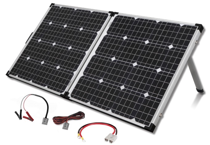
12V 110W Folding Solar Panel and Charge Controller ZM9175
User Manual
USER MANUAL
Please ensure that you have read the product manual and instructions in full prior to use. Failure to do so may result in incorrect operation and therefore impact the product’s performance.
PART LIST
1 x 110W Mono-Crystalline Solar Panel with 12V/10A Charge Regulator. (USB Version)1 x 5m Extension Lead with Anderson Connectors 1 x Anderson to Alligator Clips Lead1 x Anderson to Eye Terminals Lead1 x Heavy Duty Bag
INSTALLATION GUIDE
Step 1:Locate a clear sunlit area free from overhanging branches or heavy shade.Step 2:Unfold the solar panels, adjust the two supports to a suitable angle.Step 3:Always face the front side of solar panels towards the sun.Wipe down the panels with a microfiber cloth to remove any dust or debris.
A Note:
To ensure maximum possible output we recommend that the solar panels are regularly re-aligned to follow the sun’s movement.Wipe the solar panel with a microfiber cloth for maximum efficiency.
Folding Solar Kit Specifications
| Type | Mono-Crystalline Solar Cells |
| Peak Power | 110W(+5% ) (SSW each) |
| Rated Voltage | 12V |
| Voltage Peak Power | 17.9V |
| Current @ Peak Power | 6.15A |
| Open Circuit Voltage | 21. 5V |
| Short Circuit Current | 6.56A |
| Maximum system Vohage | 1000V DC |
| Panel Dimensions | 525(W) X 665(H) X 75(D)mm (Folded)1050(W) X 665(H) X 35(D)mm (Unfolded) |
ABOUT THE REGULATOR
- Safety Information
- Read all of the instructions in the manual before
- DO NOT disassemble or attempt to repair the
- Disconnect the solar panel before installing or moving the
- Power connections must remain tight to avoid excessive heating from a loose connection.
- Only charge 12V batteries that comply with the parameters of
- Battery connection may be wired to one battery or a battery
2. Overview
The 12V/10A regulator is a PWM charge regulator with USB output that uses the most advanced digital technique. Regulator features as follows:
- Support 3 charging options: AGM, Gel &FIooded lead acid battery
- Battery status LED indicator indicates battery condition
- The USB will provide power supply that can charge electronic equipment
- Battery type and load output can be set by pressing a button
- Extensive Electronic protection
3. Product Features
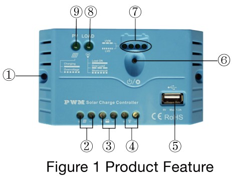
| 1. | Mounting Hole 6 4.5 | 6. | Button |
| 2. | PV Terminals | 7. | Battery status LED indicator |
| 3. | Battery Terminals | 8. | Load status LED indicator |
| 4. | Load Terminals | 9. | Charging status LED indicator |
| 5. | USB output port |
4. Wiring
- Before connecting solar charger kit with battery, please MAKE SURE the solar panel surfaces are covered or facing ground since the correct connection sequence is Battery first, then Loads if any, Solar panels to be connected
- After powering the regulator, check the Battery LED indicator on the regulator, to be solid green. Otherwise please refer to section
5. LED INDICATORS
- Charging and load status indicator
| Indicator | Color | Status | Instruction |
|
Charging status LED indicator |
Green | On Solid | Charging |
| Green | OFF | No Charging | |
| Green | Fast Flashing | Battery Over Voltage | |
|
Load status LED indicator |
Green | On Solid | Load ON |
| Green | OFF | Load OFF | |
| Green | Slowly Flashing | Load overload | |
| Green | Fast Flashing | Load short circuit |
2. Battery status indicator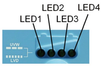
| LED1 | LED2 | LED3 | LED4 | Battery Status |
| Slowly Flashing | x | x | x | Under voltage |
| Fast Flashing | x | x | x | Over-discharge |
Battery LED indicator status during voltage is up
| O O | x | x 12.8V<Ubat<13.4V |
| O g | p | 13.4V<Ubat<14.1V |
| O O | O | O 14.1V<Ubat |
Battery LED indicator status during voltage is down
| O | O | x | 12.8V<Ubat<13.4V |
| O | x | x | 12.4V<Ubat<12.8V |
| O | x | x | Ubat<12.4V |
NOTE: 01″O” LED indicator ON; “x” LED indicator OFF.
Setting Operation
(1)Load ON/OFF SettingWhen the regulator is powered on, press the button to control the load output. NOTE: The USB will output when the load is on.
Battery Type SettingOperation:Step 1: Enter setting mode by pressing the button for 5 seconds until the battery status LEDs are flashing.Step 2: Select the desired mode by pressing a button.Step 3: The mode will be saved automatically without any operation for 5 seconds and LED will stop flashing.
Battery Type Indicator
|
LED1 |
LED2 | LED3 |
Battery type |
|
Ο |
× |
× |
AGM/Lead Acid(Default) |
|
Ο |
Ο |
× |
Gel |
|
Ο |
Ο |
Ο |
Flooded |
NOTE: “o” LED indicator ON “x” LED indicator OFF
Protection
- Battery Over Voltage Protection
When the battery voltage reaches the set point of Over Voltage Disconnect Voltage(OVD), the regulator will stop charging the battery to protect the battery from being overcharged.
- Battery Over-Discharge Protection
When the battery voltage reaches the set point of Low Voltage Disconnect Voltage(LVD), the regulator will stop discharging the battery to protect the battery from being over-discharged.
- Load Overload Protection
Load will be switched off when 1.25 times rated current overload will occur. User has to reduce load appliance, then press the button or repower the regulator.
- Load Short Circuit Protection
Load will be switched off when load short circuit (+3 times rated current) will occur. The user has to clear the short circuit, then press the button or restart the regulator.
- High Voltage Transients Protection
The regulator is protected against small high voltage transients. In lightning-prone areas, additional external suppression is recommended.
Troubleshooting
| Faults | Possible reasons | Troubleshooting |
| LED Charging indicator turn off duñngdaytme when sunshine falls on PV modules properly |
PV array disconnection |
Confirm that PV and battery wire connections are correct and tight |
| No LED indicator | Battery voltage may be less than 8V | Measure battery voltage with the multi-meter.Min.8V can start up the regulator |
| Charging status LED indicator Fast flashing | Battery Over Voltage | Check if the battery voltage is higher than OVD, and disconnect the PV |
| LED1 Fast flashing | Battery over-discharged | When the battery voltage is restored to or above the LVR point (low voltage reconnect voltage), the load will recover |
| Load status LED indicator slowly flashing | Load overload | @PIease reduce the number of electric equipment.OzPress the button or repower the regulator |
| Load status LED indicator fast flashing | Load short circuit | @Check carefully loads connection, clear the fault 2Press the button or repower the regulator. |
Technical Specifications – Charge Controller
| Nominal system voltage | 12VDC |
| Rated charge current | 10A |
| Rated discharge current | 10A |
| Battery input voltage range | 8V 16V |
| Max. PV open circuit voltage | 30V |
| Self-consumption | 12V<5mA |
| Charge Circuit Voltage Drop | 0.13V |
| USB Output Port | 5VDC/1.2A |
| Working environment temperature | -35°C-+55°C |
| Humidity | 95% N.C. |
| Mounting hole size | 64.5 |
Battery Voltage Control ParametersBelow parameters are in 12V system at 25ºC
|
Battery Type |
AGM | Gel |
Flooded |
| Over Voltage Disconnect Voltage | 16.0V | 16.0V | 16.0V |
| Charging Limit Voltage | 15.0V | 15.0V | 15.0V |
| Over Voltage Reconnect Voltage | 15.0V | 15.0V | 15.0V |
| Equalize Charging Voltage | 14.6V | —— | 14.8V |
| Boost Charging Voltage | 14.4V | 14.2V | 14.6V |
| Float Charging Voltage | 13.8V | 13.8V | 13.8V |
| Boost Reconnect Charging Voltage | 13.2V | 13.2V | 13.2V |
| Low Voltage Reconnect Voltage | 11.6V | 11.6V | 11.6V |
| Under Voltage Warning Reconnect Voltage | 12.2V | 12.2V | 12.2V |
| Low Voltage Disconnect Voltage | 11.1V | 11.1V | 11.1V |
| Discharging Limit Voltage | 10.6V | 10.6V | 10.6V |
| Equalize Duration | 120 min. | —— | 120 min. |
| Boost Duration | 120 min. | 120 min. | 120 min. |
Distributed by:TechBrands by Electus Distribution Pty. Ltd. 320 Victoria Rd, RydalmereNSW 2116 AustraliaPh: 1300 738 555Int’l: +61 2 8832 3200Fax: 1300 738 500www.techbrands.comMade in China
[xyz-ips snippet=”download-snippet”]