POWERTECH 12V 130W Folding Solar Panel and Charge Controller User Manual
USER MANUAL
Please ensure that you have read the product manual and instructions in full prior to use. Failure to do so may result in incorrect operation and thereforeimpact on the products performance.
PART LIST
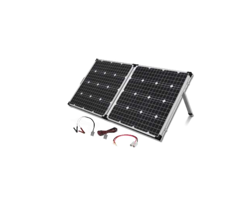
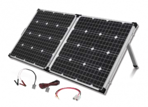
1 x 130W Mono Crystalline Solar Panel with 12V/1 OA Charge Regulator.(USB Version)1 x Sm Extension Lead with Anderson Connectors1 x Anderson to Alligator Clips Lead1 x Anderson to Eye Terminals Lead1 x Heavy Duty Bag
INSTALLATION GUIDE
Step 1:Locate a clear sunlit area free from overhanging branches or heavy shade.
Step 2:Unfold the solar panels, adjust the two supports to a suitable angle.
Step 3:Always face the front side of solar panels towards the sun. Wipe down the panels with a microfiber cloth to remove any dust or debris .
.A. Note:To ensure maximum possible output we recommend that the solar panels are regularly re-aligned to follow the sun’s movement.Wipe the solar panel with microfiber cloth for maximum efficiency.
Folding Solar Kit Specifications
| Type | Mono Crystalline Solar Cells |
| Peak Power | 130W(±5% ) ( 65W each) |
| Rated Voltage | 12V |
| Peak Power | 17.6V |
| Current @ Peak Power | 7.39A |
| Open Circuit Voltage | 21.70V |
| Short Circuit Current | 7.68A |
| Maximum system Voltage | 1000V DC |
| Panel Dimensions | 664(W) x 631 (H) x 75(D)mm (Folded)1270(W) x 664(H) x 35(D)mm (Unfolded) |
ABOUT THE REGULATOR
1. Safety Information
- Read all of the instructions in the manual before installation.
- DO NOT disassemble or attempt to repair the regulator.
- Disconnect the solar panel before installing or moving the regulator.
- Power connections must remain tight to avoid excessive heating from a loose connection.
- Only charge 12V batteries that comply with the parameters of regulator.
- Battery connection may be wired to one battery or a battery bank.
2. Overview
The 12V/1 0A regulator is a PWM charge regulator with USB output that uses the most advanced digital technique. Regulator features as follows:
- Support 3 charging options: AGM, Gel &Flooded lead acid battery
- Battery status LED indicator indicates battery condition
- The USB will provide power supply that can charge electronic equipment
- Battery type and load output can be set by pressing a button
- Extensive Electronic protection
3. Product Features
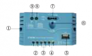
| 1 | Mounting Hole <1>4.5 |
| 2 | PV Terminals |
| 3 | Battery Terminals |
| 4 | Load Terminals |
| 5 | USB Output Port |
| 6 | Button |
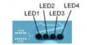
| 7 | Battery status LED indicator |
| 8 | Load status LED indicator |
| 9 | Charging status LED indicator |
4. Wiring
- Before connecting solar charger kit with battery, please MAKE SURE the solar panel surfaces are covered or facing ground, since the correct connection sequence is Battery first, then Loads if any, Solar panels to be connected last.
- After powering the regulator, check the Battery LED indicator on the regulator, to be solid green. Otherwise please refer to section 8.
5. LED Indicators
(1) Charging and load status indicator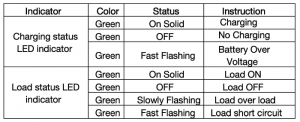
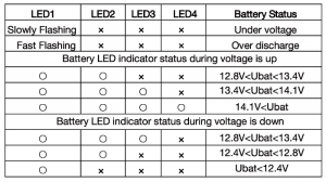
2) Battery status indicator
6. Setting Operation
(1)Load ON/OFF SettingWhen the regulator is powered on, press the button to control the load output.NOTE: The USB will output when the load is on.(2)Battery Type Setting
Operation:
Step 1: Enter setting mode by pressing button for 5 seconds until the battery status LEDs are flashing.Step 2: Select the desired mode by pressing button.Step 3: The mode will be saved automatically without any operation for 5 seconds and LED will stop flashing. Battery Type Indicator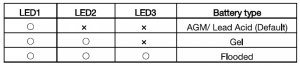
NOTE: “o”LED indicator ON “x”LED indicator OFF
7. Protection
- Battery Over Voltage Protection When the battery voltage reaches the set point of Over Voltage Disconnect Voltage(OVD), the regulator will stop charging the battery to protect the battery from being over charged.
- Battery Over Discharge Protection When the battery voltage reaches the set point of Low Voltage Disconnect Voltage(LVD), the regulator will stop discharging the battery to protect thebattery from being over discharged.
- Load Overload Protection Load will be switched off when 1.25 times rated current overload will occur . User has to reduce load appliance, then press the button or repower the regulator.
- Load Short Circuit Protection Load will be switched off when load short circuit (>3 times rated current) will occur . User has to clear short circuit, then press the button or restart theregulator.
- High Voltage Transients Protection The regulator is protected against small high voltage transients. In lightning prone areas, additional external suppression is recommended.
8. Troubleshooting

9.Technical Specifications – Charge Controller
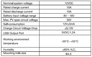
Battery Voltage Control Parameters Below parameters are in 12V system at 25 °C.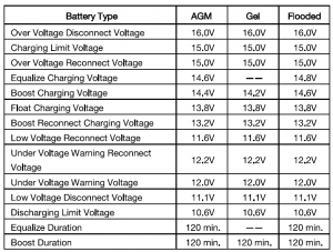
Read More About This Manual & Download PDF:
[xyz-ips snippet=”download-snippet”]