![]() 50AMPPT Solar Charge Controllerfor Lithium or SLA BatteriesMP3745User Manual
50AMPPT Solar Charge Controllerfor Lithium or SLA BatteriesMP3745User Manual
Matters needing attention
- Keep the product out of reach of children to avoid using it as a toy and causing personal injury.Note!
- Only use the accessories approved by the company or fully comply with the requirements of the company for the specifications of the accessories, or else it may cause danger.
- Operating voltage range of the charger: 12/24/36/48V battery; it will damage the internal discharge circuit if the voltage exceeds 75V, so do not use batteries over 60V, or else it may damage the charger.
- The maximum open-circuit voltage of PV is 135V. Do not exceed the range during use, or else the charger may be damaged.
- Do not touch the heat sink in the process of product operation to avoid hot hands. It is recommended to use the product on the wall.
- Operating temperature: -10+40°C.
- It is strictly forbidden to use in an environment that may be exposed to rain, which may cause danger.
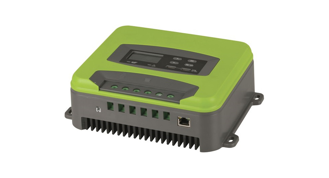
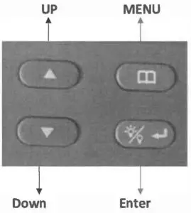
Product picture (Fig. 1)
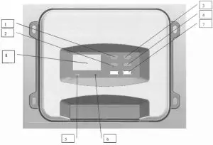
Functional description of each part of the panel (refer to Fig. 1&2):
- UP (up button}
- Down (down button}
- MENU (main menu button}
- Enter (OK button)
- Green LED light (off when no charging, flashing during charging, stay on when fully charged).
- Red LED light (Red LED light (off when no error, error alarm when the light is long on, lithium battery only has 12V gear, other gear flashing red light error)
- 2*3A USB output
- LCD screenRemark: (The operations of panel items 1-4 are explained below}.

- External temperature probe
- RJ45 port, connected to the remote control board through the network cable and synchronized with the LCD screen (this port is reserved and the remote control board is optional)
- PV+ (connected to the positive electrode of the solar panel)
- PV- (connected to the negative electrode of the solar panel)
- B+ (connected to the positive electrode of the battery)
- B- (connected to the negative electrode of the battery)
- L+ (connected to the positive electrode of the load)
- L- (connected to the negative electrode of the load)

Description of basic functions
- PV (solar panel input):a.The maximum open-circuit voltage of PV is 135V.b.PV integrates anti-reverse (reverse connection alarm EB, no charging, please eliminate the fault).c.12V battery, PV input voltage range is 16-108V;24V battery, PV input voltage range is 32-108Vd.36V battery, PV input voltage range is 48-108V;48V battery, PV input voltage range is 64-108V.
- Battery output functiona.Identify 12//2.4/36/48V battery automatically; the maximum charging current is :12/2.4V/50A,36V/35A,48V/2.5A.b.Anti-reverse connection (El alarm).
- Load output function (default OFF).a.Rated maximum output current S0A (12/2.4/36/48V).b.Overcurrent protection >55A.c.Short circuit protection (E4 alarm; please eliminate the fault).d.Load output over/undervoltage protection, recovery voltage; refer to the set voltage.
- Over-temperature protectiona.Reduce load in case of over-temperature: the charging current is always 28-30A when the heat sink temperature ≥75°€.b.Recover when the load is reduced: resume normal charging( 50A) when the heat sink temperature is <70C.c.Stop charging when the heat sink temperature is 2>90°C; resume charging when the heat sink temperature is <60°C.
- External temperature compensation function (only for AGM/STD battery)a. 1. The system will automatically adjust the float voltage according to the ambient temperature. The external temperature probe is preferred. If the external temperature probe is not connected (or the external temperature is <40C), use (temperature 2> 20C- 5C) by default. 2. The voltage may vary when the input energy is insufficient to stabilize the energy required for the float charging.b. For 12/24/36/48V batteries, when the external probe temperature < 0C40°C, the float charging voltage is 14.1/28.2/42.3V/56.4VFor 12/24/36/48V batteries, when the external probe temperature is 0C20°C, the float charging voltage is 13.8/27.6/41.4/55.2VFor 12/24/36/48V batteries, when the external probe temperature is> 20°C, the float charging voltage is 13.5/27/40.5V/54V.
- WIFI networking functionsa. The product may integrate a WIFI module or not.b.If the product integrates a WIFI module, you can install the mobile APP, control the load switch through the APP and view the MPPT charger data in real-time, such as battery voltage, charging current, etc.
- The LCD backlight is turned off if there is no button operation in 1 minute; any button operation will automatically activate the LCD backlight.
- a. USB battery input undervoltage/overvoltage protection (10.5V/60V), battery input undervoltage/overvoltage recovery (11V/9V);c.USB output25/A.
Description of LCD screen:
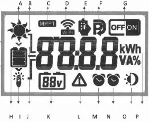
A. Sun icon, displayed when the solar panel is connected.B. Sunlight icon, 8 in total, display according to the charging currentC. MPPT icon indicates the MPPT charger.D. WIFL icon; turn on WIFI through button settings, read product data, and control load output through APP.E. Remote control icon; displayed when the remote control is connected (remote control optional).F. Settings icon; turn on when entering the set parameters, and turn off when exit.D. WIFI icon; WIFI ON/OFF optional, default ON.F. Battery level icon; display the corresponding icon according to the battery voltage.I. Load icon; turn on when the load is turned on, synchronized with the load switch ON.J. Connector, three, up corresponding to PV, middle corresponding to the battery, down corresponding to load.K. Currently identified battery type (12/24/36/48V).L. Protection icon. When this icon appears, it indicates that the machine has some protection, such as load overcurrent, short circuit protection, under-voltage protection, etc. (Refer to the fault code).M. Load timing clock 2.N. Load timing clock 1.0. Daytime and night icons; PV>12, display daytime icon![]() , py12V, display night icon
, py12V, display night icon ![]() ‘after 5 minutes. Pv<5V displays the night icon
‘after 5 minutes. Pv<5V displays the night icon ![]() imediately.P. Numerical display (8888 characters). The current data of the machine can be switched by the MODE button, such as battery voltage/ load voltage/ PV voltage/ time.
imediately.P. Numerical display (8888 characters). The current data of the machine can be switched by the MODE button, such as battery voltage/ load voltage/ PV voltage/ time.
a.Press in default interface after power-on: Switch among battery voltage, load voltage, PV voltage, and time interface in turn.b.Press and hold MENU to enter the parameter setting interface![]() . Then, press to switch among the 8 interfaces in turn.
. Then, press to switch among the 8 interfaces in turn.
- Battery type selection S (STD), default level /L (LI)/ A (AGM));
- WIFI switch ON/OFF, default ON)
- Load Undervoltage protection setting: setting range of 12V batteries: 10-11.5V, default 10V; setting range of 24V batteries: 18-23V, default 21V; setting range of 36V batteries: 30-34.5, default 30V; setting range of 48V:40-46, default 40V).
- Load undervoltage recovery setting: setting range of 12V batteries: 12-13V, default 12.5V; setting range of 24V batteries: 24-26V, default 25V; setting range of 36V batteries:36-39V,default 37.SV;setting range of 48V:48-SSV,default S0V ).
- Time setting: 24-hour system, hour/minute can be set).
- LO mode: a. Clock 1 setting range 0-120 minutes, default 60 minutes. b. Clock 2 setting range 0-120 minutes, default 30 minutes. c. Clock 1 trigger condition, when PV voltage <10V, the output turns on after N minutes load delay. d. Clock 2 trigger condition, when PV>l0.SV, the output turns off after N minutes load delay, so the loop is repeated)
- LD mode: The clock setting range is 0-12 hours. a. Clock 1 trigger condition: When PV<10V, clock 1 turns on the load for N minutes {clock 1 is set to 3 hours by default), and clock 2 executes following clock 1. b. Clock 2 turns off the load for N minutes (clock 2 is set to 4 hours by default); c. After clocking 2 executes, the load is always on until PV>10.5V, so the loop is repeated)
- TO mode: Set the load timer on/off time; the setting range is 0-24 hours.a. for example, the default setting: turn on the load at 18:00, turn offload at 6:00. The program automatically turns on/off the load at a set time).Remark: The load switch mode of items 6-8 is OFF by default. Please turn it on as needed, and set the required time
Press and hold MENU to enter the parameter setting Interface![]() .
.
1. Press MENU to switch among the 8 interfaces in sequence. 2 Press MENU to cancel the data that has been modified but hasn’t been saved.d. Restore the default settings: first press and hold the MENU button, then turn on the power of the battery, and the FFFF icon will be displayed on the screen.
Enter the parameter setting interface: press: UP/ (time plus 1 / voltage plus 0.lV); press and hold: (time/ load voltage) values can be accumulated.Press in default interface after power-on: switch among (battery voltage/current), (load voltage/current) and (PV voltage/current).
Enter the parameter setting interface and press: DOWN/ (time minus 1 / voltage minus 0.lV); press and hold: (time/ load voltage) value can be reduced cumulatively. Press in default interface after power-on: Switch among battery current, load current, and PV current.
Press: a. In the parameter setting interface: enter to modify parameters/ confirm the modificationb. In the battery voltage interface: load ON/OFF.
Wire diameter requirements:
 report this ad
Battery output line: (S0A MAX) 6AWG–8AWG; at least 8AWG copper wire, less than 2m.PV input line: 8AWG–10AWG; professionals can select the appropriate electronic line according to the actual output PV voltage.
Electrical Parameters:
| PV input | Parameters |
| PV maximum open-circuit voltage (VDC) | 135V |
| MPPT voltage (VDC) | 16-108V |
| Maximum PV input power (W) | 12V battery ≤700W; 24 -4svbattery≤ 1500W; |
| Maximum MPPT current | (12/24V) /50A; 36V/35A;48V/25A |
| DC output | |
| Battery voltage (UDC) | 12//24/35/48V |
| Battery capacity (Ali) | ≥50AH |
| Output current (A) | 50A |
| Constant voltage charging voltage | STD:14AV/28.8V/43.2V/57.6V LI:14.5VAGM14.6V/29.2V/43.8V/58.4V |
| Load output | |
| Output voltage (VDC) | 12/24/36/48V |
| Output current (A) | 50A/SSA |
| We output | |
| Output voltage (VDC) | 5 |
| Number of USB ports | 2 |
| Maximum output current (A) | 3.4A Max |
| Standby current | Battery input 12V |
| Separate MPPT charger | <60mA |
| MPPT charger+ WIFI module | <160 mA |
| Protective function | |
| PV/battery input high/low voltageprotection | Yes |
| PV/battery reverse connection protection | Yes |
| Load overcurrent / short circuit protection | Yes |
| Temperature protection | Yes (90°C) |
| Mechanical dimensions | |
| Length X width X height (mm) | 238*177*73 |
| Weight | 2.3 KG |
| General data | |
| Operating temperature (°C) | -10~ +40 |
| Cooling method | Heat sink |
| Insulation class | CLASS 1 |
| Protection level | IP30 |
Fault Codes
| El | Battery reverse connection (please correct) |
| E2 | Battery open circuit protection (battery not comected / or low battery voltage |
| B | Battery overcurrent protection (the circuit has a constant current function; the machine may be damaged if there is an error) |
| E4 | Load overcurrent /short circuit protection (error 105, turn on the load after eliminating the error) |
| ES | Battery overvoltage (battery damaged or high battery voltage) |
| E6 | PV (solar) Input overvoltage protection (PV>135V) |
| E7 | Over-temperature protection, stop charging when heat sink temperature a 90t; resume when temperature 5 SOT |
| ES | PV reverse connection (please correct) |
| Battery over and under-voltage protection range | ||
| Battery Capadty:12V/24V/36V/48V | low-voltage protection LCD display: El | <8/18/27/36V |
| Battery Capacity:12V/24V/36V/48V | Overvoltage protection LCD display: ES | >15/31/45/60V |
Remark: Please eliminate the fault according to the error code. If the machine still does not respond after the error is eliminated, it may be damaged and need after-sales service.Distributed By:Electus Distribution Pty. Ltd.320 Victoria Rd, RydalmereNSW 2116 Australiawww.electusdistribution.com.au
[xyz-ips snippet=”download-snippet”]