Poynting MIMO-3-V2 User Guide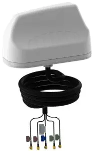
Packing Check List
|
Item |
Description |
Quantity |
|
1. |
A-MIMO-0003-V2 Antenna only | 1 |
| 2. | Adhesive Foam Discs |
1 |
|
3. |
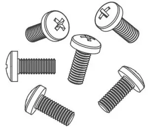
M4 x 12mm Stainless Steel Screws | 6 |
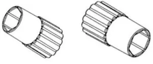
| 4. | Grip Extenders |
5* |
|
5. |
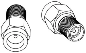
SMA(f) to RP- SMA(m) Adapter | 2* |
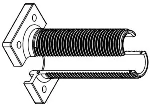
| 6. | 10mm Threaded Spigot |
1 |
|
7. |
50mm Threaded Spigot | 1 |
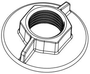
| 8. | Plastic Nut |
1 |
|
9. |
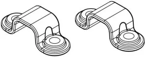
Cable Clips | 2 |
| 10. | Spigot Seal |
1 |
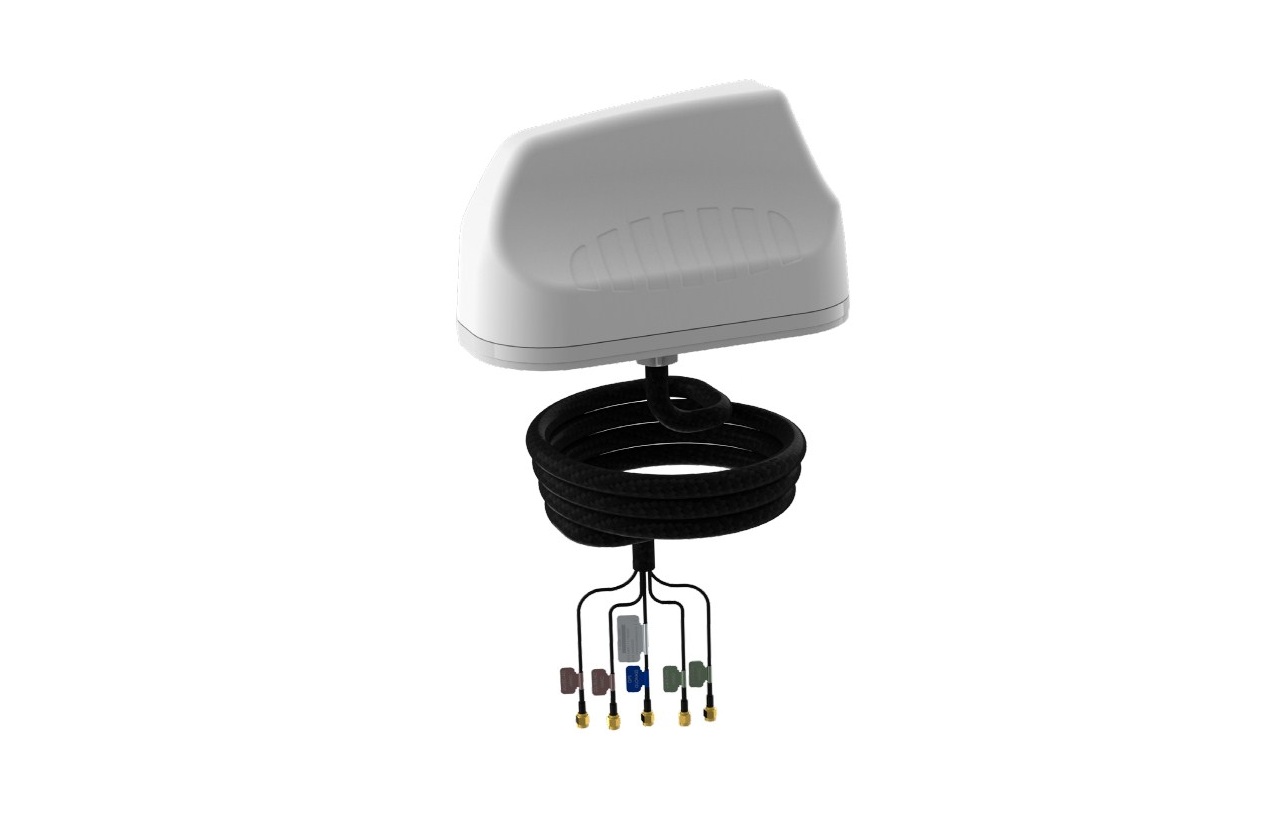
Packing Check List
The appearance of each component
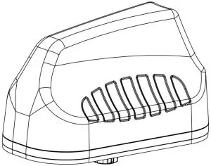
- Antenna Unit

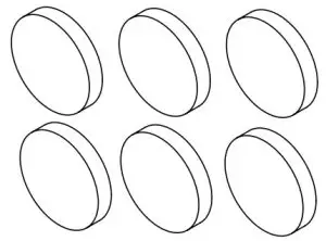
- Adhesive Foam Discs
- 10mm Threaded Spigot
- 6x (M4 x 12mm) Stainless Steel Screws
- Plastic Nut
- *SMA(f) to RP-SMA(m) Adapter
- 50mm Threaded Spigot
- Grip Extenders
- Cable Clips
- Spigot Seal
Antenna with Wi-Fi only
Tools Required
Item
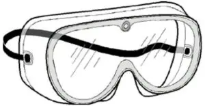
- Safety goggles
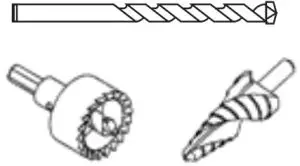
- Drills (Pilot drill (3mm) and Hole saw (22mm) or step drill (4 – 22mm))
- Masking tape
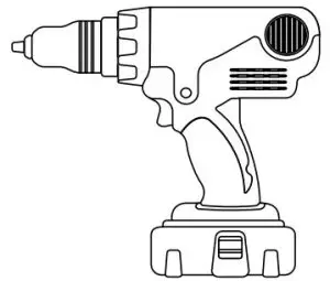
- Hand drilling machine
- Centre punch
- Hammer
- 27mm spanner/wrench
- Drilling template (Available on www.poynting.tech/downloads)

Optional Accessories
Optional Accessories
- Various Cable extensions are available
- Magnetic Base Kit
Introduction
This User Guide provides information on the installation instructions of the MIMO-3-V2 antenna.
Installation Instructions
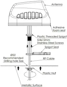
Threaded Spigot Mounting
Download the 1:1 drill template from http://www.poynting.tech/downloads
- Choose the mounting location carefully and a position at least 50cm from heat sources, with a clear line of sight to the sky. It is recommended that the antenna be installed at the highest possible location on the vehicle’s roof so that a signal can be received in a 360° radius, clear of obstacles including parts of the vehicle’s body and that the mounting surface is as flat as possible. The selected location must have a conductive metallic surface area which is a minimum of ±400x400mm to achieve optimal performance.
- Once you have decided on the location and checked that there are no obstructions such as cables or channels below the mounting surface, for the fastening nut and cables to pass through, use the downloaded 1:1 drill template to mark the mounting location.
- To prevent the marking tool or drill sliding off course, use masking tape over the drilling point to help hold the drill point in place. The masking tape also prevents hot shavings from the drill or hole saw which could penetrate and damage the painted surface.
- Set the drilling machine to low speed and carefully drill a pilot hole (Ø3mm drilling bit works well). Use a Ø22mm metal hole saw or step drill to open the hole to the required size.Note: The recommended drill hole diameter for MIMO-3-V2 is Ø22mm
- Clean the entire surface on which you plan to mount the antenna. Cleaning is done so as not to damage the vehicle’s paint and to ensure good contact of the foam surface to the mounting area.
- Alcohol wipes can be used to remove oil and dirt from the surface.
- Remove the wax protection paper from the adhesive foam seal at the base of the antenna.
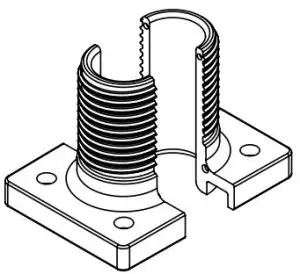
- Insert the antenna cables and threaded spigot through the drilled hole.
- Push the antenna down onto the mounting surface and make sure the antenna is placed straight and correctly.
- Fit the plastic nut from the inside of the mounting platform.
- Be careful not to over tighten the nut.
- You may use the 6 x (M4 x 10mm) brass threaded inserts to further secure the antenna. Please refer to the drilling template for hole locations. The use of M4 threaded rod is the preferred fastening method.
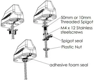
- The 10mm Threaded Spigot should be used to secure the antenna to a surface structure of 10mm thickness or less. Likewise, the 50mmThreaded Spigot should be used to secure the antenna to a surface structure of 50mm thickness or less.
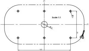
Download the Drilling template as shown in image below
Installation Drill Hole Template
Threaded Spigot Mounting

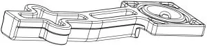
Surface mounting
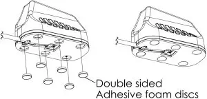
Adhesive surface mounting
- Clean the entire surface on which you plan to stick the antenna
- Remove Nut, spigot seal and Short spigot from antenna
- Push the Rf cable into the groove in the plastic base
- Secure cable with the 2 x cable clips and 4 x (M4 x 12mm) stainless steel screws
- Pull off the one side of the adhesive wax paper of each of the 6 x adhesive foam discs.
Adhesive surface mount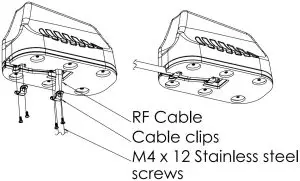
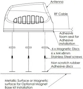
Optional magnetic base kit
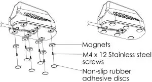
Optional magnetic base kit
Antenna Mounting Precautions
- Place the antenna at the highest point possible and ensure that there aren’t any surrounding obstructions to the antenna.
- In order to avoid communication interference ensure that the antenna is placed at least 0.5m away from other antennas and metal objects.
- Avoid installing the antenna near a chimney, as the smoke and soot emitted by the chimney can obstruct the signal level achieved by the antenna.
- Install the antenna away from heat sources and flammable gases.
Cable Routing
- Avoid wrapping the cables around the pole.Route the antenna cables straight down the inside of the pole to avoid using extra equipment such as cable ties.
- Use the minimum cable length required. Do not run more cable than needed to ensure minimum cable losses are achieved.
- Never pull on the cable connectors; pull only on the cable ensuring the cable is not under tension.
- The allowable cable bend radius is 30mm.
- Cover connector with insulation tape before threading them through a hole.
Safety
- If you are installing an antenna for the first time or unsure about how to install your antenna, obtain the help of a professional installer.
- Carefully survey the installation site before installation to locate secure handholds, dangerous conditions (such as power lines and weak roofs) and the safest and most convenient placement for ladders if necessary.
When installing your antenna, remember:
- Do not install near power lines as they can electrocute you.
- Do not install on a wet or windy day or when lightning or thunder is in the area.
- Wear shoes with rubber soles and heels and protective clothing (long sleeve shirt or jacket) and rubber gloves.
- Avoid operating while under the influence of drugs, alcohol or medication.
- Make sure that any loose fitting jewelry or clothing is secured and tie back long hair as they can get caught in moving parts during installation.
- If the antenna starts to fall, step away to avoid harm.
When drilling, remember:
- Use safety goggles when drilling the holes.
- Avoid using bits that are dull, bent or damaged.
- Be aware of where your fingers are in relation to the drill bit when using the drilling machine (i.e., don’t drill into your hand).
- To stop the drilling machine, let the drill chuck come to a complete stop on its own.Do not grasp the chuck in an attempt to stop the drill bit.
- Avoid awkward hand positions where a sudden slip could cause a hand to move into the drill bit or cutting tool.
CAUTION:
Antennas must be installed to provide a separation distance of at least 20cm from all persons so as to comply with SAR (Specific Absorption Rate) RF Exposure requirements.
European Waste Electronic Equipment Directive 2002/96/EC
![]() Please ensure that old waste electricals and electronics are recycled.
Please ensure that old waste electricals and electronics are recycled.
Directive 2011/65/EU (RoHS 2)
 report this ad
![]() This product is fully compliant with the RoHS 2 directive.
This product is fully compliant with the RoHS 2 directive.
References
[xyz-ips snippet=”download-snippet”]