Poynting WLAN-61
South AfricaUnit 4, N1 Industrial ParkLandmarks AveSamrand, 0157,South AfricaTel: +27 12 657 0050[email protected]
EuropeKronstadler Straße 4,81677 MünchenGermanyTel: +49 89 2080 265 38Mob.: +49 176 529 733 50[email protected]
Packing Check List
| Item | Description | Quantity |
| 1. | A-WLAN-0061
Antenna only |
1 |
| 2. | Cast U-shape | 1 |
| 3. | M6 x 60mm U-bolt
-ss* |
2 |
| 4. | Cast connector rod | 1 |
| 5. | Cast square base | 1 |
| 6. | M6 washers -ss* | 10 |
| 7. | M6 nylock nut-ss* | 2 |
| 8. | M6x12mm hex bolt- ss* | 1 |
| 9. | M6x16mm hex bolt
– ss* |
3 |
| 10. | M6 nuts-ss* | 4 |
| 11. | M6x25mm hex bolt
–ss* |
2 |
| 12. | Rubber seal barrel | 1 |
| 13. | Main body with back housing | 1 |
| 14. | Rubber flat seal | 1 |
| 15. | Rubber conical seal | 1 |
| 16. | Plastic wrench | 1 |
Stainless Steel
| The appearance of each component |
| Antenna Unit |
 |
| Stainless steel bracket assembly |
 |
| Bracket mounting kit |
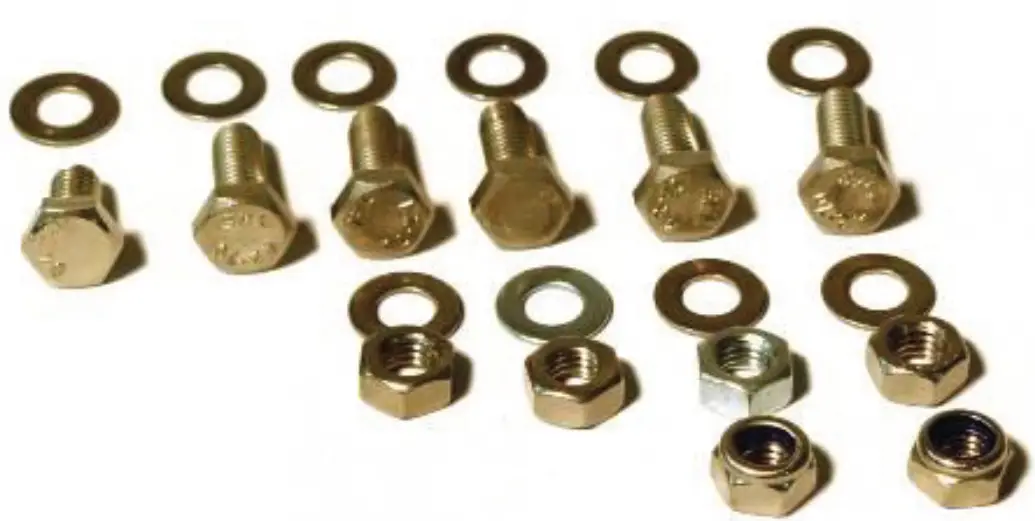 |
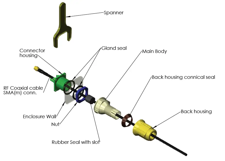
| Cable gland components |
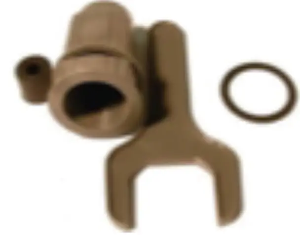 |
Tools Required
| Tools that may be required: |
| 6mm Masonry drill bit |
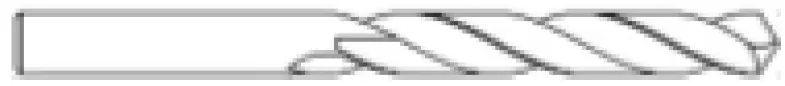 |
| Impact drilling machine |
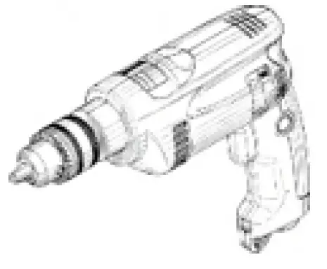 |
| Screw driver-Cross slot/Philips |
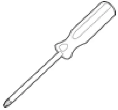 |
| Hammer |
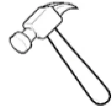 |
| Safety goggles |
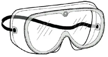 |
| Spanner/Wrench |
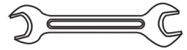 |
Mounting Configuration
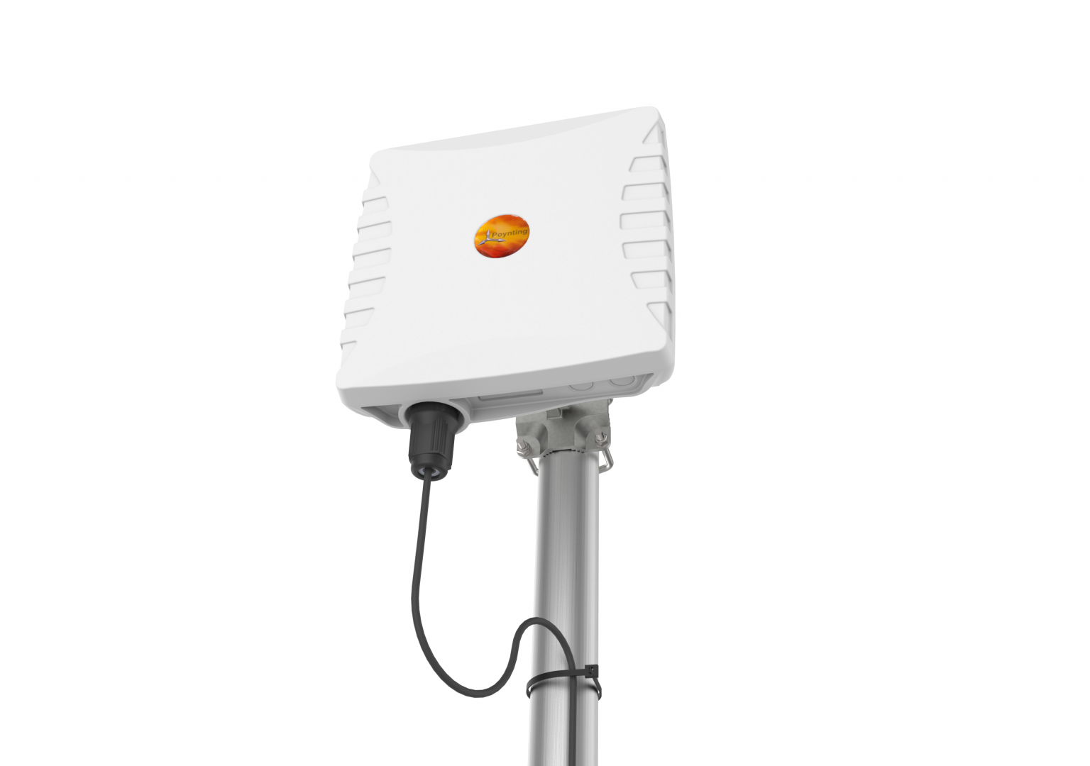
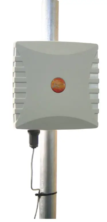
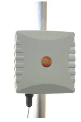
WLAN-0061 is a pole mountable dual band WiFi antenna. It can be mounted outdoors on a pole of up to 50mm in diameter or wall mount.Follow the instructions below for installation.
Pole Mounting
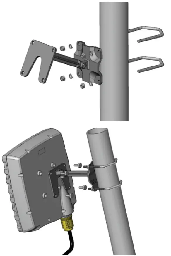
- Lay the antenna out at the installation site.
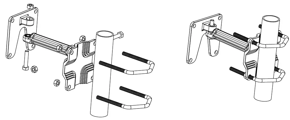
- Attach the cast U-shape bracket component to the antenna by means of four M6 washers, three M6 x16mm hex bolts and one M6x12mm hex bolt-which goes into a point marked earthing point.
- Use two M6 x 25mm hex bolts, two M6 nylock nuts, two M6 washers to attach Cast-U-shape and Cast square on two opposite ends of the Cast connector rod.
- Attach the assembly to a mast (diameter 32 ~50mm) using the Cast square base, two U- bolts, four washers and four M6 nuts.
- Point the antenna in the desired orientation by swivel adjustment of azimuth and/or ele-vation in two points.
- Do not overtighten the nuts/bolts onto the bracket components in all places.
- Mount the antenna so that there is at least 1meter of clearance in all directions around it and unobstructed line of sight to the cell tower’s strongest signal.
- Earth the pole.
Wall Mounting
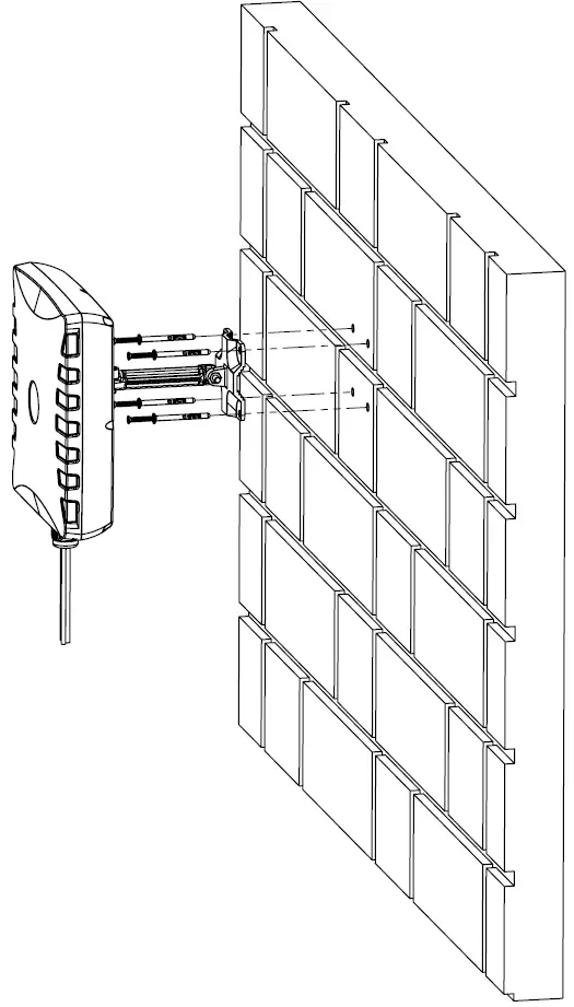
- This antenna should be mounted on a wall using the wall plugs as shown in the figure below
- Strain relieve the cable to the wall with
- saddles or cable tie to the closest structure.
- Connect the end of cable to radio device.
Antenna Mounting Precautions
- Place the antenna at the highest point possible and ensure that there aren’t any surrounding obstructions to the antenna.
- In order to avoid communication interference, ensure that the antenna is placed at least 0.5m away from other antennas and metal objects.
- Avoid installing the antenna near a chimney, as the smoke and soot emitted by the chimney can obstruct the signal level achieved by the antenna.
- Install the antenna away from heat sources and flammable gases.
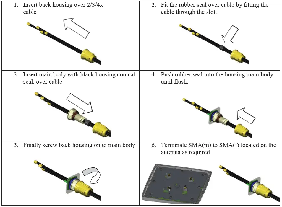
Cable Gland Preparation
Cable Routing
- Avoid wrapping the cables around the pole. Route the antenna cables straight down the inside of the pole to avoid using extra equipment such as cable ties.
- Use the minimum cable length required. Do not run more cable than needed to ensure minimum cable losses are achieved.
- Never pull on the cable connectors; pull only on the cable ensuring the cable is not under tension.
- The allowable cable bend radius is 30mm.
- Cover connector with insulation tape before threading them through a hole.
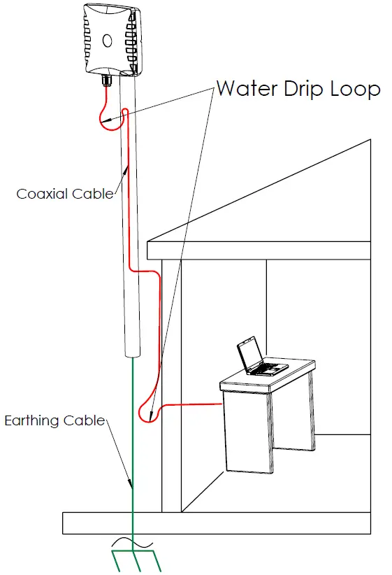
- If the cable goes through the wall and the entry is higher or above the antenna connector – make sure the cable is installed with a drip loop so that water does not run down to the connector
Safety
- If you are installing an antenna for the first time or unsure about how to install your antenna, obtain the help of a professional installer.
- Carefully survey the installation site before installation to locate secure handholds, dangerous conditions (such as power lines and weak roofs) and the safest and most convenient placement for ladders if necessary.
- When installing your antenna, remember:
- Do not install near power lines as they can electrocute you.
- Do not install on a wet or windy day or when lighting or thunder is in the area.
- Wear shoes with rubber soles and heels and protective clothing (long sleeve shirt or jacket) and rubber gloves.
- Avoid operating while under the influence of drugs, alcohol or medication.
- Make sure that any loose fitting jewellery or clothing is secured and tie back long hair as they can get caught in moving parts during installation.
- If the antenna assemble starts to fall, get away from it and let it fall to avoid harm to yourself.
- Earth all outside antenna mountings such as the mounting pole and brackets.
- When drilling, remember
- Use safety goggles when drilling the holes.
- Avoid using bits that are dull, bent or damaged.
- Be aware of where your fingers are in relation to the drill bit when using the drilling machine.
- To stop the drilling machine, let the drill chuck come to a complete stop on its own. Do not grasp the chuck in an attempt to stop the drill bit.
- Avoid awkward hand positions where a sudden slip could cause a hand to move into the drill bit or cutting tool.
 report this ad
CAUTION: Antennas must be installed to provide a separation distance of at least 20cm from all persons so as to comply with SAR (Specific Absorption Rate) RF Exposure requirements.European Waste Electronic Equipment Directive 2002/96/EC Please ensure that old waste electricals and electronics are recycled. Directive 2011/65/EU (RoHS 2)This product is fully compliant with the RoHS 2 directive.
[xyz-ips snippet=”download-snippet”]