
APSSECRSSecurity and Remote StartQuick Installation GuideFor Complete Installation Guide and Technical SupportPlease visit: www.voxxuniversity.comOr Call1-800-225-6074
REV. B2020 Voxx Electronics. All Rights Reserved.
NotificationsAlarmWhen the alarm is triggered the system will provide feedback to the user. Upon disarm, the system will beep 4x and flash the LED to indicate the Alarm Trigger Zone.
| 1 | Shock |
| 2 | Trunk / Hood |
| 3 | Door |
If the remote start fails to start the vehicle, the system will flash the vehicle parking lights to indicate the cause.
| 1 | Runme Expired |
| 2 | Remote Shutdown |
| 3 | Brake On |
| 4 | Manual Mode |
| 5 | Hood Open |
| 6 | Low / No Tach |
| 7 | Tach Programming |
| 8 | High Tach |
Chirp DeleteSystem ARM/DISARM chirps can be toggled ON or OFF without entering the Feature Bank programming.
- Turn the ignition key ON/OFF.
- Press and release the valet button three (3) times.
The system will respond with one (1) chirp for ON and two (2) Chirps for OFF. This feature will not affect alarm trigger or programming.User Programmable LED System LED notifications can be turned ON or OFF without entering Feature Bank programming.
- Turn the ignition key ON/OFF, ON/OFF.
- Press and hold valet button for five (5) seconds.
The LED will flash one (1) time for ON, two (2) times for OFF. This feature will not affect LED flash during programming.
Remote Programming
The APSSECRS does not include an RF remote kit. The RF remote kit Includes two (2) remotes, one (1) antenna, and one (1) cable. When added, remotes must be programmed to the system. Remote Programming is located in Feature Bank 1. To enter Remote Auto Programming:
- Turn the ignition key to ON.
- Press and release the valet button three (3) times. The system will beep and flash the parking lights one (1) time.
Press the lock button on each remote. The system will beep one (1) time to indicate the remote has been programmed. If programming one (1) button remotes press the Start button. Only primary remote functions are auto-programmed. This Includes Lock, Unlock, and Trunk/Start.If using AUX output control, you must manually program the AUX output channels to the remote. Please see the complete installation guide for manual remote programminginstruction.Note: If programming 2-Way remotes, wait for the remote to beep before programming additional remotes. This beep is confirmation that a 2-Way response has been receivedfrom the main module.
Feature Programming
The APSSECRS Feature Banks can be programmed by using the valet button and remote.To enter Feature Bank programming:
- Turn the ignition key to ON.
- Press and release the valet button three (3) times. The system will beep and flashlights one (1) time for Feature Bank 1, Remote Programming.
- Cycle ignition key OFF/ON. The system will beep and flashlights two (2) times for Feature Bank 2.
- Press valet button to cycle features. LED will flash to display the feature number.
- Press lock button to cycle options. The system will beep to indicate option number.
- Cycle ignition key OFF/ON. The system will beep and flashlights three (3) times for Feature Bank 3.
- Press valet button to cycle features. LED will flash to display the feature number.
- Press lock to cycle options. The system will beep to indicate the option Number.
Tach Programming
The installer must manually configure the Engine Confirmation method in Feature Bank 3, Feature 5. The default method is “Tach”. When using the default “Tach” method, the vehicle tach rate must be programmed. To enter tach rate programming:
- Turn the ignition key ON.
- Press and release the valet button three (3) times.
- Turn the ignition key OFF.
- Press and hold valet button.
- While holding valet button, start the engine using the key.
- Hold the valet button for approximately ten (10) seconds. If connected to the vehicle Tach source, the system will flash the parking lights one (1) time every second.
- Release the valet button. The system will turn on the parking lights for two (2) seconds to indicate the tach rate is programmed.
The tach rate can also be programmed without the use of a valet button. This is helpful when using the OEM remote of CarLink system to control this module. To program the tach rate without a valet button:
- Turn the ignition key to the ON position and start the vehicle’s engine.
- Wait for Engine RPM to lower to a normal idle.
- Press and hold the vehicle’s brake pedal.
- Press the LOCK button on the OEM remote or the Carlin App.
Note: Programming tach signal via OEM or Telematics control is only available on Firmware v1.47 or Higher.
Data Protocol Selection
The default data port protocol of this model is ADS (iDatalink 2-Way). This model is capable of detecting the correct data port protocol (ADS or DBI) and automatically configuring Feature Bank 2; Feature 18. To initialize the detection procedure:
- Press and hold the valet button.
- Cycle the vehicle’s Ignition ON/OFF two (2) times.
- Release the valet button.
The system will automatically detect and set the correct data port protocol, ADS or DBI. Note: This feature is only available on module firmware v2.0 or higher.The Feature Banks below can also be programmed using the FlashLogic Weblink or Weblink Mobile.
| Feature Bank 2 | Options | |||||||
| 1 Chirp | 2 Chirp | 3 Chirp | 4 Chirp | 5 Chirp | 6 Chirp | |||
| Features | 1 | Lock / Unlock Function | 500ms | 3.5sec | 500ms L, DBL UL | DBL L, 5COms UL | DBL L, DBL UL | 500ms L, 350ms UL |
| 2 | Ignition Lock | OFF | ON | |||||
| 3 | Ignition Unlock | OFF | Unlock All | Unlock Driver | ||||
| 4 | Exterior Illumination | OFF | With Arm | With Disarm | With Arm & Disarm | |||
| 5 | Auto Relock | OFF | Auto-Lock Only | Auto-Lock & Arm | ||||
| 6 | Auto Arrning/ Locking | OFF | Auto Arrn Only | Auto-Lock & Arm | ||||
| 7 | Notification Sound | Both | Siren | Horn | ||||
| 8 | Horn Timing | 16ms | 30ms | 40ms | Wens | 10ms | ||
| 9 | Valet Override Method | Valet | Custom Code | Stand Alone Valet | ||||
| 10 | Driver Priority Unlock | OFF | ON | |||||
| 11 | Silent Choice | OFF | From Transmitter | OEM Style | ||||
| 12 | Security Profile | All On | Doors off | Hood/trunk Off | All Off | All On w/ OEM RS | ||
| 13 | Door Trigger Input | Negative | Positive | |||||
| 14 | Park Light / Trunk Swap | OFF | ON | |||||
| 15 | Data Port Protocol | ADS | DBI | |||||
| 16 | Dome Light Delay Timer | OFF/Program | 15sec | 30sec | 45sec | 60sec | 120sec | |
| 17 | Alarm Trigger Legnth | 30sec | 45sec | 60sec | 90sec | 120sec | ||
| Feature Bank 3 | Options | |||||||
| 1 Chirp | 2 Chirp | 3 Chirp | 4 chirp | S Chirp | 6 Chirp | |||
|
Features |
1 | Defrost Output | Pulsed | 10min | RS Runtime | |||
| 2 | RS Start Notification | ON | OFF | |||||
| 3 | RS Runtime | 15min | 20min | 45min | 60min | 5min | 10min | |
| 4 | RS Parking Lights | Steady | Flashing | |||||
| 5 | Engine Confirmation | Tach | Voltage | Data | Hybrid | |||
| 6 | Voltage Level | >0.5v 84 Start | <0.5v B4 Start | |||||
| 7 | Ignition 2 Output | Ignition | Accessory | Start | ||||
| 8 | Ignition 3 Output | Ignition | Accessory | Start | ||||
| 9 | Accessory Output | Accessory | Ignition | Start | ||||
| 10 | Transmission | Auto | Manual | |||||
| 11 | Max Crank Time | 0.8sec | 1.0sec | 1.5sec | 2.0sec | 3. Osec | 4. Osec | |
| 12 | Diesel Delay | OFF | Diesel 5 | Diesel 10 | Diesel 15 | Diesel 20 | Diesel 30 | |
| 13 | Temperature Start | OFF | 14 F | SF | OF | -4 F | -14 F | |
| 14 | Crank Duration | Averaging | Preset | |||||
| 15 | RS Shock Override | Shunt until Clear | Shunt RS Cycle | Shunt From TX | ||||
| 16 | Turbo Timer | OFF | 3min | 5min | 10min | |||
| 17 | Start Activation | Two Press | One-Press | Three Press | ||||
| 18 | RS Lock Function | No Change | UL Before L After | UL Before Start | Lock After Start | |||
| 19 | Factory Disarm Output | Single Pulse | Double Pulse | 350ms | 500ms | 800ms | Same As Bank 2, Fl | |
| 20 | Additional Unlock Pulse | No Pulse | IGN, ACC, GWR | IGN,ACC,GWR,PASD |
Dome Delay Programming
This system can be programmed to ignore the vehicle’s theater dimming dome light. This feature will be used when connecting the door trigger input to the dome light circuit for the alarm trigger.Start with all doors closed and the vehicle dome light off.
- Press Lock, Unlock, Lock, Unlock, Lock, Unlock, Lock. LED will light solid.
- Open and close the driver’s door.
The system will monitor the dome light circuit. When the dome light turns off the system will set the delay time and add an additional two (2) seconds.Dome Delay Reset
- Key ON/OFF, ON/OFF, ON/OFF.
- Press and hold valet button for five (5) seconds.
The system will beep one (1) time to indicate reset is complete.
Programmable Input Control
Programmable Input Control allows any PIC be configured to one of the options listed below. This feature is accessible via FlashLogic Weblink or Weblink Mobile.
| Door Trigger | Full Shock Trigger |
| Trunk Trigger | Parking Brake |
| Hood Trigger | Brake |
| N.C. Door Trigger | External Start Activation |
| Pre-Warn Shock Trigger | Diesel Glow Plug |
Negative Output Control (NOC)
Negative output control allows any NOC to be programmed for any one of the options
| Lock | Ground While Armed |
| Unlock | Ground While Disarmed |
| 2nd Unlock | Domelight |
| Trunk | Headlight |
| Remote Start Status | Defrost |
| Ignition | LED |
| Factory Disarm | Ch. 4 AUX |
| Factory Arm | Ch. 5 AUX |
| Accessory | Ch. 6 AUX |
| Pulse During Crank | Ch. 7 AUX |
| Pulse Atier Shutdown |
AUX Output Control
Any AUX output can be configured using the AUX Control Menu. This feature is only accessible via FlashLogic Weblink or Weblink Mobile.
APSSECRSSecurity and Remote StartSystem LayoutImportant Update
The default Data Port Protocol of this system is ADS. If using a FLCAN or other external integration modules be sure to choose iDatalink 2-Way when flashing.This system will also support DBI Protocol. This will require programming Feature Bank 2, Feature 15 to DBI.
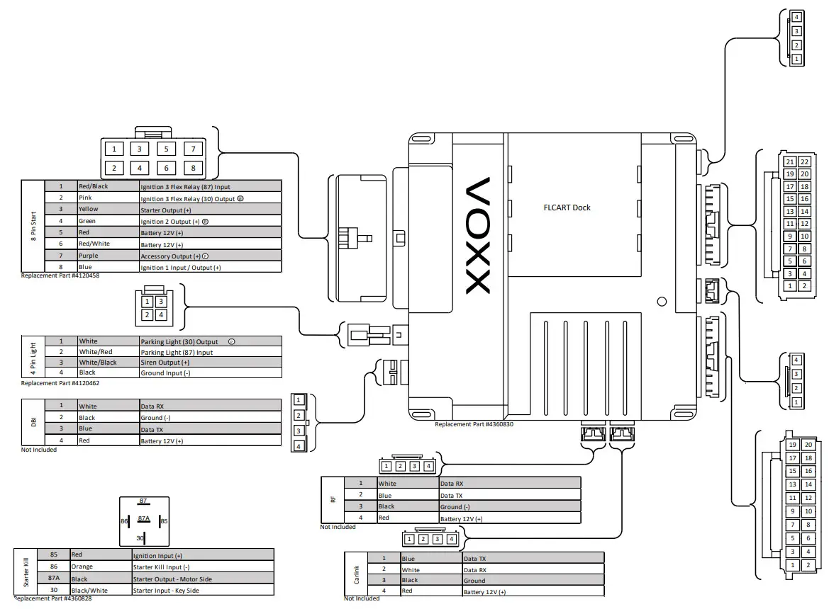
| Shock | 4 | Red | Battery 12V (+) |
| 3 | Black | Data TX | |
| 2 | Blue | Warn Away | |
| 1 | Green | Full Trigger |
Replacement Part #4120459
| 22 Pin Input/Output | 22 | Green | Unlock Output (-) (NOC 11) |
| 21 | Dk. Blue | Trunk Output (-) (NOC 9) | |
| 20 | Red | Lock Output (-) (NOC 10) | |
| 19 | Green/Lt. Blue | Ch. 4 AUX Output (-) (NOC 8) | |
| 18 | Black/White | Horn Output (-) | |
| 17 | Lt. Blue/Green | Ch. 5 AUX Output (-) (NOC 7) | |
| 16 | Red/Black | 2nd Unlock Output (-) (NOC 12) | |
| 15 | Black/Lt. Green | Factory Arm Output (-) NOC 6) | |
| 14 | Brown/Black | Brake Input (+) (PIC 6) | |
| 13 | Black/Blue | Factory Disarm Output (-) (NOC 5) | |
| 12 | Dk. Blue/Black | External Activation Input (-) (PIC 5) | |
| 11 | Black/Red | Pulse After Shutdown Output (-) (NOC 4) | |
| 10 | Orange/Black | Parking Brake Input (-) (PIC 4) | |
| 9 | Black/Yellow | Pulse During Crank Output (-) (NOC 3) | |
| 8 | Green/Yellow | Diesel Glow Plug Input (4-) (PIC 3) | |
| 7 | Green/White | HomeLight Output (-) (NOC 2) | |
| 6 | Purple/Brown | Door Trigger Input (- / +) | |
| 5 | Lt. Blue | Remote Start Status Output (-) (NOC 1) | |
| 4 | Green/Orange | Tach Input (-) | |
| 3 | Gray/Black | Hood Input (-) (PIC 2) | |
| 2 | Lt. Green | Trunk Trigger Input (-) (PIC 1) | |
| 1 | Orange | Starter Kill Relay / Anti-Grind Output (-) |
Replacement Part #4120457
| Weblink | 4 | Red | Battery 12V (+) |
| 3 | Black | Ground (-) | |
| 2 | Blue | Data TX | |
| 1 | White | Data RX |
Not Included
This Harness is included with the FLCART.For Wire Information and Diagram Please Refer to Vehicle SpecificFlashLogic Install Guide.Visit www.FlashLogic.com for More Information.Not Included
| Compatible RF Kits | |
| PE1BZ | PE2LEDZ |
| PE1BZLR | PE2LCDZ |
| PE1BTWZ | PE1M2LEDZ |
| PE5BZ | PE1M2LCDZ |
For Complete Installation Guide and Technical Support Visit www.voxxuniversity.com. Or Call 1-800-225-6074
 report this ad
REV. B2020 Voxx Electronics. All Rights Reserved.
References
[xyz-ips snippet=”download-snippet”]