
pro MIS Digital Video Colposcope 

PREFACE
This manual contains information, which may not be copied or duplicated, in full or in part, without the explicit approval of Promis Medical (Australia) Pty Ltd. We reserve the right to make any change in the operator manual, which may affect instructions in this manual, without giving prior notice. The user of this equipment shall be solely responsible for any kind of damage, malfunction to the unit or user as a result of improper use or any kind of repair or alteration done by anyone other than us or a technician duly authorized by the manufacturer to do so.This operator manual provides directions for using COLpro222DX-OZview Digital Video Colposcope. Read all instructions, cautions and warnings prior to use. Failure to follow instructions or to heed warnings could lead to patient or operator injury. COLpro222DX-OZview version is our newest, most advanced and recently upgraded model of our COLpro222DX series. Many additional facilities have been added according to the feedback received from various users and stakeholders of our widely acclaimed COLpro222DX series. The Delivered Product may vary slightly in color or shape or specifications due to continuous product development.
DESCRIPTION OF COLpro222DX-OZview
COLpro222DX-OZview is an aid to colposcopy. Colposcopy is a gynecological procedure in which the doctor, using colposcope looks at the cervix. It comprises of a camera head mounted on a vertical stand. This instrument magnifies the cervix, vagina and external genital area when the doctor points out the camera head at the vagina where a speculum has been placed.
It incorporates latest digital signal processing technology to provide high-resolution images for effective colposcopy. It is a latest generation video colposcope incorporating advanced CCD imaging & illumination technology, aerodynamic design, compact size and offers powerful features like automatic as well as manual focus, electronic multi-grade green filter and magnification indicator among many others. The extra innovative features added are e-flip & mirror image, facility to vary the light intensity, facility to choose various color contrasts to make colposcopy more effective.
COLpro222DX-OZview is designed to detect the presence of pre-cancerous tissue or cancerous tissue or any abnormality in cervix area. So far colposcopy plays a significant role in evaluation and treatment of cervical infection like cervical cancer, erosion and inflammation. This manual has been prepared to provide authorized personnel with information on the assembly, functions and routine performance related to the COLpro222DX-OZview. It is provided together with the device and should be available near the device all the time. The user must read and be familiar with the contents of this manual before using the video colposcope. Operation must be performed in accordance with stipulated safety standard thus to ensure patient and operator’s safety.
GENERAL WARNINGS & PRECAUTIONS
Intended Use: For examination of the tissues of the vagina, cervix and external genitalia by means of magnification to investigate abnormal cervical cytology or suspicious lesions of the lower female genital tract. Also used for corresponding biopsy and treatment, when indicated.Environmental Requirements:
- Area of camera & Floor stand pole: 0. 4m2
- Ambient temperature: 50C – 400C
- Humidity: < 80%
- Atmospheric pressure: 70 kPa-106kPa
- AC 100~240 V, 50/60 Hz
- Well-grounded
Symbols and Terminology
Attention: Consult user’s manual for additional informationCaution: This statements identifies a condition or practice, which if not corrected or discontinued immediately, could lead to equipment failure or damage.Warning: This identifies a condition or symbols practice, which if not corrected or discontinued immediately, could lead to patient injury / illness.
WARNINGS
The Colposcope must be connected to a properly installed power outlet with protective earth contacts only. Operation room should be ventilated and free of shock, noise, other strong interference source and direct sunlight.
- Users of this equipment should be thoroughly trained in the appropriate medical procedures. They should take time to read and understand these instructions before performing any procedure. They can also read and follow instructions for any other equipment used in conjuction with the Colposcope.
- The Colposcope should not be operated in the presence of flammable or explosive gases or chemicals, or installed in areas where these materials are commonly used.
- Keep all liquids away from electrical equipment to avoid the possibility of shock and instrument damage.
- Colposcope user should adhere to the operating conditions found in this manual. Otherwise, instrument damage may occur and patient safety may be compromised.
- All signal input and output are intended for connection to only peripheral devices that are compliant to IEC 60601 – 1 or other IEC standards as appropriate to the nature of the peripheral device. Connecting additional peripheral to the video colposcope may increase the risk associated with chassis or patient leakage currents. To maintain operator & patient safety, the user should consider the system leakage current requirements of IEC 60601-1.
- Never stare at the illuminator because it is extremely bright and may cause injury to the eye.
CAUTIONS
- Occasionally inspect the power cord for signs of cuts, abrasions or dents.
- The colposcope should never be stored or operated in areas where it could get wet or could be exposed to any environmental conditions like extreme temperature or humidity, direct sunlight, dust etc.
- There are no user serviceable parts in this unit or in its accessories. Any attempt to disassemble and repair this unit will result in voiding of the warranty.
- Do not clean illuminator or lens with alcohol. Do not touch optical parts or lenses.
- Do not sterilize
- Do not immerse any part of the unit in cleaning solutions.
PRECAUTIONS
- Colposcope Safety: The safety requirement mentioned in this section is for Colposcope as a whole and applies to the instrument. The importance is not related to the sequence. NOTE: This is not a treatment device.
- Please confirm the colposcope is in normal working condition before operation.
- Without losing knob, the excessive force may damage twin axis adapter of colposcope head.
- This is non-contact type examination device, avoid contacting patient during use.
- Before turning off power supply of the whole system, never plug or unplug the video cable.
- Without written approval of the manufacturer, user shall not remove, modify or use accessories, which do not comply with the manufacturer’s requirements.
- When connecting the signal cables, handle them carefully. Align the connectors, do not plug or unplug with strong force, otherwise, the cable and connectors may be damaged, which will impact the image quality or camera power supply or even the equipment
- When not in use, the colposcope power supply shall be turned off, and the camera shall be covered to prevent dust.
- To prevent accidental power failure and other potential accidents, use uninterruptible power system with the colposcope.
- Before cleaning the system, make sure to disconnect the system power cable.
- Clean according to the items specified by Promis Medical (Australia) Pty Ltd.
- Keep cellular phones away from the device.
- Packing materials should be put away from children reach or handled according to related regulations.
- In case any doubt arises, please consult with Promis Medical (Australia) Pty Ltd. as soon as possible.
- Please comply with the items stipulated in the manual. This manual is not the replacement of medical regulations.
INSTALLATION
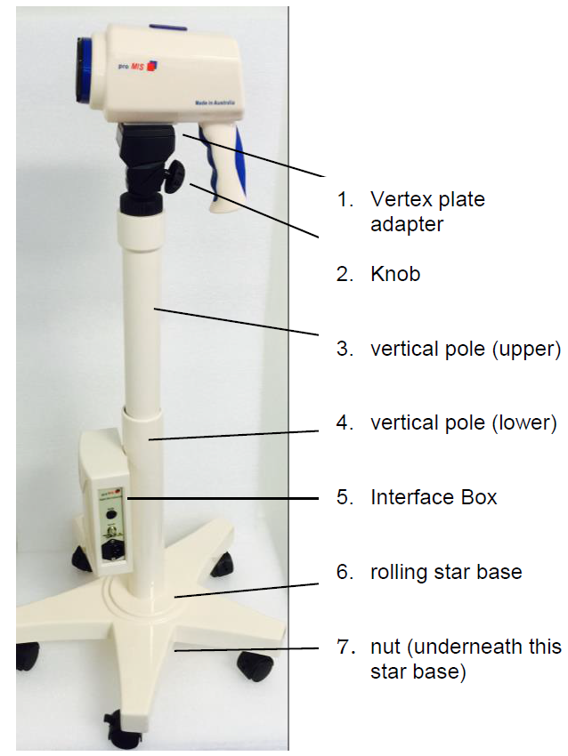
COLpro222DX-OZview is an easy system to install. Please be sure that all electrical, electronic and environmental requirements are met before installation of the system.Installation: Composition & AssemblyVertical Pole Composition: Vertical pole (lower) “FIGURE A. 4.” with interface box “FIGURE A. 5.” can be connected to the external display monitor to constitute a complete diagnosis system. It can also be connected to computer workstation to save, analyze print patient information etc. Its height can be adjusted according to actual needs.External Cable of interface box
- Use accompanying power cord; insert one end into “FIGURE B. 3.” and the other end to power socket in wall.
- Connect one end of S-Video cable / BNC cable to “FIGURE B. 1.” / “FIGURE B. 2.” and the other end to an external display monitor.

ASSEMBLING STEPS
STEP 1: Grasp the lower vertical pole “FIGURE A. 4.” and put it into the middle hole of rolling base “FIGURE A. 6.”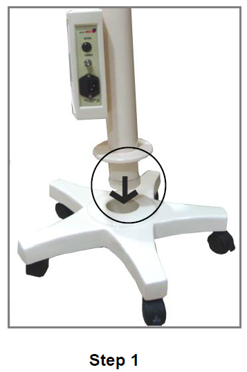
STEP 2: Screw-in the nut “FIGURE A. 7.” STEP 3: Lie down the lower vertical pole “FIGURE A. 4.”, fix the nut “FIGURE A. 7.” by rotating it clockwise, thus to fix rolling base “FIGURE A. 6.” and lower vertical pole “FIGURE A. 4.”
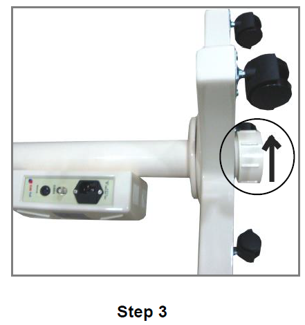
STEP 4: Insert the camera head cable (grey) into the hole of vertex plate adapter “FIGURE A. 1.”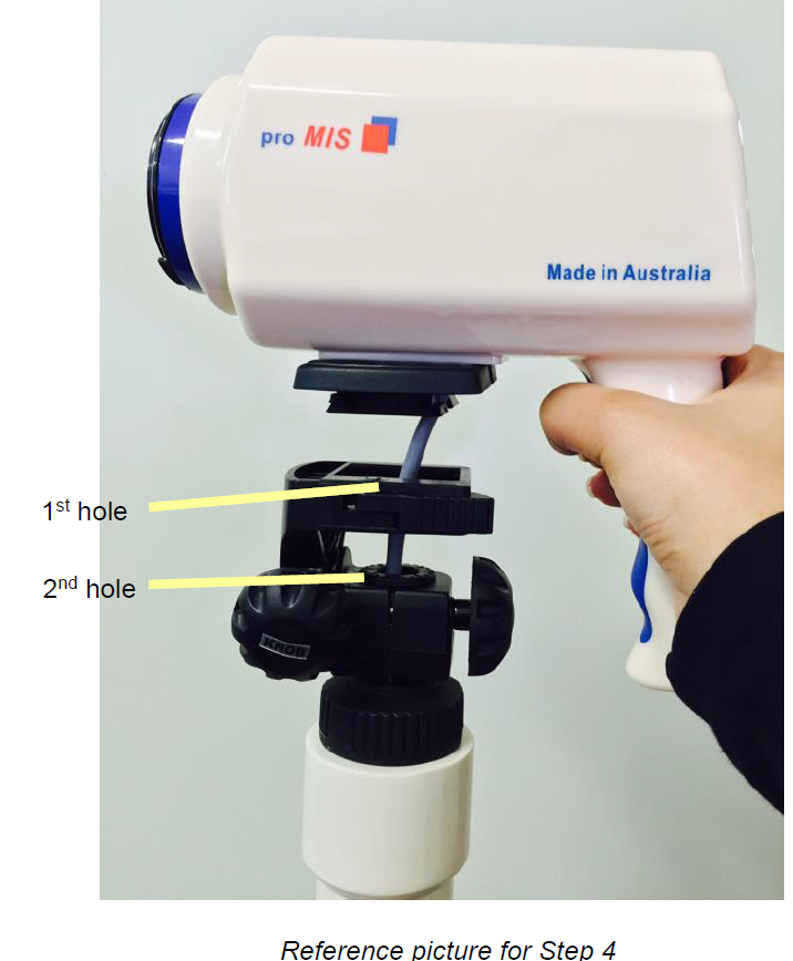
Make sure to insert the camera head cable through the first hole of vertex plate adaptor 1st and then 2nd hole as shown in the reference picture.
STEP 5: Push the cable through the upper vertical pole “FIGURE A. 3.” Until the cable comes out. Do not fix the camera on twin axis adapter now. It can cause cable twisting.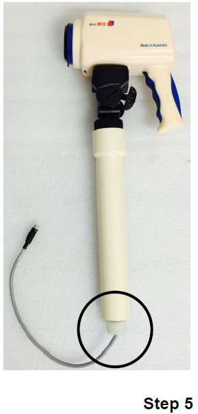
STEP 6: Connect the cable which came out in Step 5 and connect it carefully to the cable coming out of the lower vertical pole “FIGURE A. 3.” as shown in the. Please ensure to match both the arrows marking pasted on the cables.
STEP 7: Rotate the upper vertical pole “FIGURE A. 3.” clockwise and connect it with the lower vertical pole“FIGURE A. 4.”. Then rotate the camera according to the moving direction of cable, thus to avoid twisting or damaging of the cable.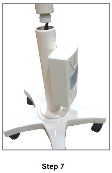
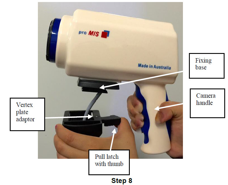
STEP 8: Pull the latch of vertex plate adaptor with thumb outside by 900, grasp the camera’s handle carefully and put the fixing base (which is attached to the camera head) into vertex plate adaptor. When the camera head is attached, release the hand grip of vertex plate.
- Lose KNOB 1 to tilt the camera head.
- Lose KNOB 2 to move the camera head sidewise (left-right).
- Lose KNOB 3 to adjust the height of the camera head (up-down).Without losing knobs, the excessive force may damage twin axis adapter of colposcope head
Please connect the electrical power cord to the AC power inlet provided on the Interface box. The other end of the power cord must be connected to a Hospital grade AC power outlet (100-240 VAC, 50/60 Hz). Interface box has SVHS video output & BNC output for connection to a suitable video device such as Medical grade monitor. Switch ON the main power button provided on the camera head panel. The system is now ready for use.
CAMERA HEAD CONTROL PANEL – FUNCTIONS
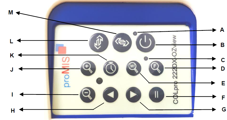
A. LED for PowerB. On/Off SwitchC. LED for Auto FocusD. Auto FocusE. Intensity Variation /Manual FocusF. Pause or freezeG. Green Filter OnH. Green Filter Off and color contrast selectorI. Zoom OutJ. Zoom InK. Timer & Zoom Factor DisplayL. E-FlipM. Mirror Image
| ◦ | LED for Power | LED next to the ON/OFF Switch lights up, when power is ON from ON/OFF switch (B) |
| ON/OFF Switch | Press once to get the device camera and illuminator ON & if pressed again, it will turn OFF. | |
| ◦ | LED for Auto Focus | If the LED next to Auto Focus lights up, it means that the camera is in the auto focusing mode. When it goes off, it means that the device is in manual focus mode. When the camera is in auto focus mode, it searches the object automatically & adjusts the image clarity according to the distance between the Colposcope & the object. When the LED goes off, then the camera is in manual focus mode & it needs to be directed towards the object & could be manually adjusted to the clearest image. |
| Auto Focus | Under default condition, the unit stays in Auto focus mode that means LED
(C) is glowing. To switch ON the manual focus mode, press the auto focus button again. Under this condition, LED (C) goes off. |
|
|
|
Intensity Variation | a.: When the colposcope is in auto focus mode (i.e Auto Focus LED is glowing) then this button works as an intensity mode selector. One of the 5 Levels of Intensity can be selected by pressing this button. Level of intensity is indicated by l1, I2—–I5 on screen. I1 is the brightest of all.
b. Manual Focus: When the camera is in manual focus mode (i.e Auto Focus LED is not glowing), press this button to start manual focus. |
| Pause or Freeze | This button allows you to freeze the required image that needs to be stored for reviewing. Press the button again, image will be unfrozen. | |
| Green Filter ON
& Blue Filter |
Press this button to get the green filter ON & the system will automatically filter the red tissue in the image being observed and highlight the enhanced vascular image. It also gives the excellent color contrast for viewing vascular pattern without any light loss.
One of the 4 levels of green filter can be selected by pressing this button. First push of this button, switches from Normal image to Green Image G1/ thereafter, each next push of this button selects next levels of Green Filter. Green Filter status is Indicated by G1, G2, G3, G4 on screen. |
| Press this same button to get the Blue filter ON. First push of this button, switches from Normal image to Green Image. Each next push of this button selects next levels of Green Filter G1, G2, G3, G4. The next and last push will be B for Blue Filter. | ||
|
|
Green Filter OFF and color contrast selector | Press it once to switch green filter mode into normal Image mode. One of the 5 Color levels of Normal Image can also be selected by pressing this button. First push of this button switches Green Image into Normal Image N1. Thereafter, each next push of this button selects next levels of color contrasts which is indicated by N1, N2——-N5 on screen |
| Zoom-Out | Press this button to close the Zoom in factor | |
| Zoom- In | This button allows zooming of the image up to a certain level where one can view the tissues & vessels more clearly. | |
| Timer & Zoom factor display | Press this button to start the display of current magnification status and timer on the connected display. Press again to switch off this function. | |
|
|
E-Flip | E-flip function enables the image to rotate upside down for a better viewing of the vascular pattern. (Letter ‘E’ displayed on the screen denotes – this function is ‘ON’. |
| Mirror-Image | Mirror Image gives a side view of the image for better diagnosis. (Letter ‘M’ displayed on the screen denotes – this function is ‘ON’. |
REMOTE CONTROL FUNCTIONS

A. Gamma ONB. Gamma OFFC. Zoom IND. Zoom OUTE. PauseF. Green Filter ONG. Green Filter OFFH. Manual FocusI. Auto FocusJ. Timer & Zoom Factor DisplayK. Mirror ImageL. E-Flip
TECHNICAL SPECIFICATIONS
| Image Processor | SONY Color CCD |
| Pixels | 12 00 000 |
| Resolution | > 825 lines (standard), or > 1000 (with Gamma ON) |
| E-Flip | Yes |
| Mirror Image | Yes |
| Electronic Shutter | Automatic |
| Signal to noise ratio: | > 48 db |
| Illumination | High MCD super bright white shadow less LED light |
| Color Temperature | o 7000 K |
| Test Timer | Yes |
| Multigrade Electronic Green Filter | Yes (4 steps) |
| Blue Filter | Yes |
| Variable color contrast | Yes (5 steps) |
| Variable light intensity | Yes (5 steps) |
| Focus | Automatic and Manual |
| Focus Distance | 20 – 30cm / 30 – 40 cm |
| Zoom | 1 – 55x |
| Viewing area | f 170mm – 10mm |
| Depth of view | f 200mm – 5mm |
| Magnification display | Yes |
| Video Outputs | SD : 1 x Y/C, 1 x BNC composite |
| Safety Standard | Complies to IEC 60601 |
| Gamma Processor | Optional (through remote) |
| Remote control (optional) | For operative functions |
| Power Supply | 100-240 VAC, 50/60 Hz |
LIST OF REPLACEMENT PARTS
| Sl No | Part Description | Part Number | |
| 1 | Head Cabinet | DVC-CH-00-010 | |
| 2 | Housing of Camera | DVC-CH-00-002 | |
| 3 | Illuminator | DVC-LS-00-001 | |
| 4 | Micro Controller Unit | DVC-MC-00-001 | |
| 5 | 8 Core Cable Assembly | DVC-IC-00-001 | |
| 6 | Interface Panel | DVC-IB-00-001 | |
| 7 | Stand with vertex | DVC-STD-0-001 | |
| 8 | Camera Module | DVC-CM-00-001 | |
| 9 | Y/C Cable | DVC-SC-00-001 | |
| 10 | BNC to RC Cable | DVC-BC-00-001 | |
| 11 | Power Cord | Australia | DVC-PC-00-003 |
| Europe | DVC-PC-00-002 | ||
| South Africa & India | DVC-PC-00-001 | ||
| 12 | 12 volt power supply | DVC-IB-PS-010 |
SYSTEM MAINTENANCE
Cleaning Agent: Examples of disinfectants that can be used on the colposcope unit are listed below:
- Dilute Sodium Hypoclorite (Bleaching Agent)
- Diluted Formaldehyde 35%-37%
- Hydrogen peroxide 3%
- Alcohol 75%
Isopropanol 70%The Digital Video colposcope can be cleaned with hospital-grade ethanol and dried in air or with crisp and clean cloth.Cleaning Steps:
- Turn off camera & colposcope, cut the connection with AC power supply.
- Clean external part and stand
- Clean connecting cables.
- Wipe all the cleaned parts with dry cloth.
Warnings
- Colposcope should be powered off and disconnected from AC power before cleaning.
- Do not attempt to immerse any part of the equipment in cleaning solutions.
- Do not use abrasive material to clean any part of Colposcope.
- Do not use strong solvents to clean any part of Colposcope.
- Do not leave any solution residue on the device, if so, please wipe it off quickly with a cloth damped in water
MAINTENANCE:Please examine the following before using colposcope:
- Examine whether there is any mechanical damage
- Examine all external cables, insert parts and accessories.
- Examine all parts, which connect to patients and make sure they are in good working condition.
- If any damage is found, please contact manufacturer or its authorized technical personnel engineer.When inspecting the system, pay attention to the following:
- Make a visual inspection to ensure there are no damaged parts.
- Make sure that there is no damage between plug and cable, and all the pins and plugs are not loose.
- Check whether the connection between vertical stand, monitor & camera is correct & unbroken.
- Check there is no cable breakage by moving each end of the cable.Camera Head Maintenance:
- Camera head is an important part of colposcope, dust particles can accumulate on it and may affect colposcope performance, if fingerprint is left on the camera lens it could lower the image quality and it is really harmful to the camera lens coating, so it should be removed / cleaned quickly.
- Use soft brush to clean the camera.
- Put a drop of camera lens rinse solution on cotton paper, then use it to wipe camera surface.
Maintenance of unit
- Do not attempt to immerse any part of the equipment in cleaning solutions.
- Do not use abrasive material to clean any part of Colposcope.
- Do not use strong solvents to clean any part of Colposcope.
- Do not leave any solution residue on the device, if so, please wipe it off quickly with a cloth damped in water
WARRANTY TERMS AND CONDITIONS
Subject to any other statutory right or remedy and the warranty conditions below, this new Promis Digital Video Colposcope COLpro222DX-OZview is expressly warranted by Promis Medical (Australia) Pty Ltd to be free from defects, and to conform to product descriptions and specifications as described in this document for a period of 1 year from the date of original delivery of the COLpro222DX-OZview unit by us or Dealer or Agent to the customer. This warranty applies only to an original purchase world-wide from us or Dealer or Agent.
This warranty shall not cover damage malfunction or failure resulting from the use of COLpro222DX-OZview other than in accordance with the instructions contained in this operator manual, accident, misuse or misapplication, improper or unauthorized repair, neglect, modification or use of unauthorized accessories or improper voltage.
The warranty shall be void if the rating label or serial number is altered or removed. Apart from any warranty implied by the law that cannot be excluded and the warranty specifically provided above, Promis Medical (Australia) Pty Ltd makes no warranty representation or covenant whatsoever in respect of the COLpro222DX-OZview or any part of the COLpro222DX-OZview and all other warranties, representations, or covenants, express or implied, are hereby excluded.To obtain service under this warranty, first contact Promis Medical (Australia) Pty Ltd (see details on front page).Promis Medical (Australia) Pty Ltd will correct any warranty failure by replacing the COLpro222DX-OZview or repairing the COLpro222DX-OZview. Promis Medical Australia’s liability is limited to a liability to pay to the customer an amount equal to the cost of replacing COLpro222DX-OZview, or the cost of having the COLpro222DX-OZview repaired, whichever is the lowest amount.To the fullest extent permitted by law, the customer will not under any circumstances have any cause of action against or right to claim or recover from Promis Medical (Australia) Pty Ltd for or in respect of any negligence or economic loss of any special reliance, indirect or consequential loss, damage, or injury, including but not limited to, loss, damage or injury in connection with an incorrect diagnosis arising out of or in connection with the use or supply of the COLpro222DX-OZview or any part of it.
The customer expressly acknowledges and agrees that:
- The COLpro222DX-OZview is a technical medical device and it is the responsibility of the physician to provide the final clinical diagnosis and treatment to the patient based on all information the physician has available to him or her.
- The COLpro222DX-OZview is intended to assist the physician, not to provide a conclusive determination or to serve as a substitute for the physician’s judgment with respect to the detection and treatment; and
- All users of COLpro222DX-OZview shall be required to advise patients of the above limitations.By opening the packaging of the COLpro222DX-OZview, customers will be deemed to have read, fully understood and accepted all of the above warranty terms and conditions. If the customer does not accept the above warranty terms and conditions in their entirely, please contact Promis Medical (Australia) Pty Ltd.
CHECK LIST for ACCESSORIES for PROMIS COLpro222DX-OZview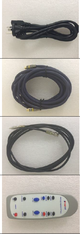

- POWER CORD
- SVHS CABLE
- BNC CABLE
- REMOTE CONTROL
- SOFTWARE INSTALLATION CD AND USB DONGLE KEY (LICENSE TO RUN THE SOFTWARE) : PART OF SOFTWARE
- USB FOOTSWITCH WITH EXTENSION CABLE : PART OF SOFTWARE
- VIDEO CAPTURE CARD : PART OF SOFTWARE
OUR CONTACT DETAILS
ADDRESS:Promis Medical (Australia) Pty LtdUnit 46, Level 3, 11-13 Brookhollow AvenueBaulkham Hills, NSW 2153, AustraliaPOSTAL ADDRESS:PO BOX 6439Baulkham Hills, NSW 2153, AustraliaEMAIL: [email protected]![]()
References
[xyz-ips snippet=”download-snippet”]