
![]()
TY-05-30 / TY-05-40 / TY-05-50User Manual
![]()
Caution

Make sure no obstacles are in the lift’s path.Make sure the lift is not touching any walls.Make sure all cords are appropriate length to accommodate the change in height.

 WARNING
Pinch PointKeep hands and fingers clear.

Keep children away from electric TV lift, control units and remotes.There is a risk of injury and electric shock
Keep all electrical components away from liquids.
Do not sit or stand on the TV lift.Do not crawl or lie under the TV lift.
Do not open any of the components – the linear actuator, control box or remote.There is a danger of electric shock.

This product is designed with a duty cycle of 10%(2 min. on, 18 min. off).
Liability
The height adjustable TV lift contains electric motors and is designed for dry areas only.
The TV lift is adjustable so that it can be positioned at the most ergonomically suitable height.
Any other use is at user’s risk.
Under no circumstances does the manufacturer accept warranty claims or liability claims for damages caused from improper use or handling of the TV lift.
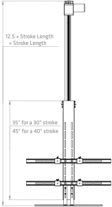
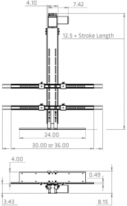
Dimensions in Inches
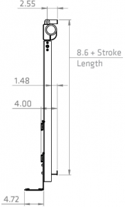
Specifications
| Model: | TY-05-30 | TY-05-40 | TY-05-50 |
| TV Maximum Height: | 30″ Stroke = 30″ Tall | 40″ Stroke = 40″ Tall | 50″ Stroke = 50″ Tall |
| Wall Mount Measurements: | 700mm x 500mm | 700mm x 700mm | 700mm x 1200mm |
| Stroke Length: | 30″ | 40″ | 50″ |
| Weight: | 25.5 lbs | 38.5 lbs | 40.3lbs |
| Speed at Full Load: | 0.9″/sec | ||
| Dynamic Load | 140 lbs | ||
| Input Voltage: | 110 – 220 VAC | ||
| Output Voltage: | 24VDC | ||
| Overload Protection: | Fused | ||
| Duty Cycle: | 10% (2 minutes on, 18 minutes off) | ||
| Limit Switch: | Built-in, non-adjustable and externally mounting | ||
| IP Grade: | IP20 | ||
| Operational Temperature: | -26ºC to +65ºC (-15ºF to 150ºF) | ||
| Certification: | CE and RoHS | ||
| Control Options: | Wired and wireless |
Electronics


Control Box x 1 Wireless Remote x 1

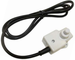
Rocker Switch (Wire 35″) x 1 External Limit Switch (Wire 60″) x 1
Hardware
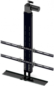
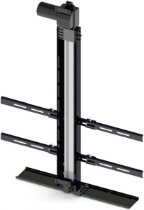
![]()
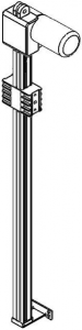
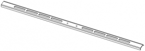
Track Linear Actuator x 1 Support Column x 1
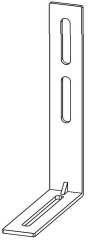
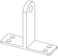
Ceiling Cover Brackets x 2 Actuator Mounting Bracket x 1

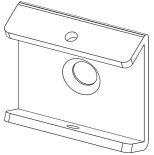
Ceiling Cover x 1 TV Mounting Brackets x 4

 TV Support Arms 30″ x 2 TV Support Arms 36″ x 2
|
Purpose |
Name |
Quantity |
| P1 Ceiling Cover Brackets |
Hex Bolt M8x18 |
4 |
|
Nut M8 |
4 |
|
|
Flat Washer M8 |
4 |
|
| P2 Ceiling Cover Brackets |
Phillips Countersunk Screw M5x12 |
4 |
|
Nut M5 |
4 |
|
|
Flat Washer M5 |
4 |
|
| P3 TV Support Arm |
Hex Bolt M8x12 |
4 |
|
Nut M8 (spare parts) |
4 |
|
|
Flat Washer M8 |
4 |
|
| P4 TV Mounting Bracket |
Thumb Screw M5 |
4 |
|
Phillips Countersunk Screw M8x12 |
4 |
|
| P5 Support Column (middle) |
Hex Bolt M10x25 |
2 |
|
Locking Washer M10 |
2 |
|
|
Flat Washer M10 |
2 |
|
| P5 Support Column (outside) |
Hex Bolt M6x25 |
4 |
|
Locking Washer M6 |
4 |
|
|
Flat Washer M6 |
4 |
|
| P6 Actuator Mounting Bracket |
Clevis Pin |
1 |
|
Cotter Pin |
1 |
Assembly Instructions
![]()
![]()
Tools needed: philips screwdriver, 5mm allen key, 6mm allen key, 8mm allen key, 8mm socket, 13mm socket
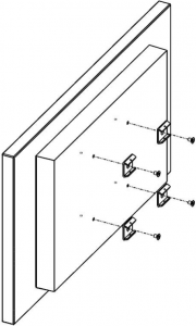
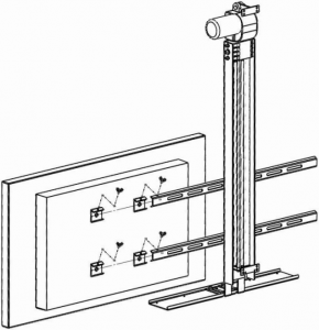
1. Use the four M8x12 Phillips Countersunk Screws from bag P4 to mount the TV Mounting Brackets to the back of your television. Please be aware that the supplied screws may not fit your television. Ensure that you have the appropriate TV mounting screws before continuing. Tighten until secure.
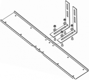
 2. Use the four M8x12 bolts, nuts and washers from bag P3 to attach TV Support Arms to the Support Column. Either the 30” or 36” TV Support Arm can be used depending on which width suits the installed TV. Tighten until secure.
3. Use the four M5x12 screws, nuts and washers from bag P2 to attach the Ceiling Cover to the Ceiling Cover Brackets. Tighten until secure.
 4. Use the four M8x18 bolts, nuts and washers from bag P1 to mount the assembled Ceiling Cover to the Support Column. Tighten until secure.

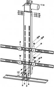
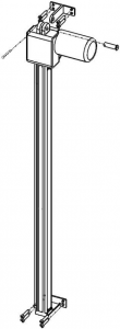
5. Use the Actuator Mount Bracket, Clevis Pin and Cotter Pin from bag P6 to mount the top portion of the Track Linear Actuator to your installation. The bottom portion comes with an attached bracket for installation. The wood screws shown in the diagram are not included. Tighten until secure.
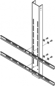
 6. For this step we recommend having at least two peope. From bag P6, use the four M6x25 bolts and washers for the smaller holes on the outside and the two M10x25 bolts and washers for the middle holes to mount the assembled Support Column to the Track Linear Actuator. Install all of the bolts before tightening to ensure proper alignment.

7. Now that your Drop Down TV Lift is assembled you can attach your TV Mounting Brackets to the TV Support Arms using the four M8x12 screws. Tighten until secure.
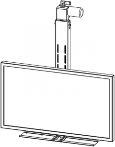
8. Your Drop Down TV Lift is now fully assembled and ready for use.
9. Pairing the Wireless Remote
Pairing the wireless remote is required before use.
- Press and hold the UP and DOWN buttons on the wireless remote while simultaneously pressing the button on the side of the control box for 10 seconds.
The TV lift will raise after the remote pairing has been completed.


10. Changing Travel Functionality
To change the wireless remotes travel function from Momentary to Non-Momentary, hold the COM button for approximately 10 seconds.
11. External Limit Switch
Please keep in mind this procedure is completely optional and does not need to be set up in order for the TV Lift to operate. The external limit switch stops the lift from moving once it is pressed. Please note that the external limit switch will only operate in the extending direction.
Install the switch in a way that it will be pressed while the lift is moving up and right before the ceiling cover touches the ceiling.
[xyz-ips snippet=”download-snippet”]