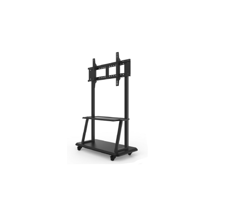
PROKORD Movable Whiteboard Cart User Manual
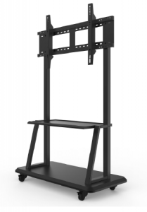
Installation Instructions for Mobile Brackets
| Mobile Stent | |||
| Number | Describe | Quantity | Position |
| 1 | Base | 1 PCS | |
| 2 | 2.5 inch universal caster belt brakes | 2 PCS | Assembly with base |
| 3 | 2.5 inch universal casters without brakes | 2 PCS | Assembly with base |
| 4 | Moving bracket column left | 1 PCS | Assembly with base |
| 5 | Moving bracket column right | 1 PCS | Assembly with base |
|
6 |
Laminate |
1 PCS |
Assembly with left and right columns |
|
7 |
Cross hexagon head composite belt M6*16 |
16 PCS |
Caster and base assembly |
|
8 |
M14 cushion (spring washer GB859), M14 flat cushion (small gasket-A grad GB848), M14 nut (type 1 hexagon nut GB6170) |
Each 4 PCS |
Pillar and base assembly |
| 9 |
Cross head combination screw M6*16 |
4 PCS |
Laminate and column assembly |
| 10 | Wall hanging beam | 1 PCS | Assembly with pillars |
| 11 |
Wall hanging vertical beam |
2 PCS | Assembly with whole machine and crossbeam |
| 12 | M5*100 crosshead screw |
2 PCS |
Assembly with wall- mounted vertical beam |
| 13 |
M8*70 cross hexagon bolt |
4 PCS |
Assembly of wall- mounted crossbeams and columns |
|
14 |
M8 cushion (spring washer GB859), M8 flat cushion (gasket-A grade GB848), M8 nut (type 1 hexagon nut GB6170) |
Each 4 PCS |
Assembly of wall- mounted crossbeams and columns |
| 15 | Hexagon wrench |
1 PCS |
Assembly of hexagonal bolts |
Mobile bracket assembly and installation steps:
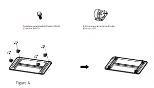
- Remove the base from the packing box. Firstly, assemble the casters to the corresponding position of the base with M6*16 bolts combined with cross screwdriver and cross hexagonal head. The operation schematic diagram is shown in Figure A.
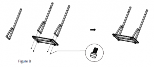
- Remove the left and right column of the movable support in turn from the packing box, insert the welded M14*70 bolt on the column into the corresponding assembly hole of the base in the direction (pay attention to the M6 thread on the side of the column in the inner side). Put M14 cushion and M14 cushion on the welded M14*70 bolt on the column in turn, and then fasten it with M14 hexagonal nut, as show in Figure B. Remove the layer board from the packing box and use M6*1610. The laminate is assembled between the left and right columns by the combination screw of the head of the word plate. The operation schematic is show in Figure C. Attention direction
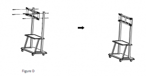
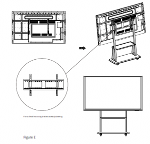
- Remove the standard wall-mounted cross beam from the packing box, assemblethe M8*70 hexagonal bolt and M8 nut with hexagonal wrench and cushion pad in turn on the left and right columns of the mobile support (upper and lower positions should be adjusted according to personal needs), and the operation schematic diagram is as shown in Figure D, rotate the M5*100 screw on the wallmounted vertical beam to the position show in the local graph a, and then assemble the wall-mounted vertical beam and the machine with a screwdriver. Draw a schematic diagram as shown in Figure E. Finally, hang the machine with the vertical beam on the wall-mounted cross beam (refer to the assembly drawing of the wall-mounted bracket), then lock the M5*100 screw to the top of the wallmounted cross beam with a long screwdriver. The operation schematic diagram is as follows: the assembly drawing of the wall-mounted bracket and the local graph B.
Be careful:
- In order to guide the installation of the conference mobile bracket correctly, please read the instructions carefullywhen installing the bracket.
- Please commission a professional installation company to install the conference mobile bracket.
- When reading or using this manual, if you do not understand it, please contact our company.
- The illustrations in this manual are for reference only. In practice, please refer to the physical objects.
Read More About This Manual & Download PDF:
[xyz-ips snippet=”download-snippet”]