R19RGBRGB19″[LED Ringlight]SPECIALIST•SERIES
Congratulations on your purchase of this ProMaster Basis R19RGB LED Ringlight. It is an RGB light that is excellent for portraiture and many types of photography and videography. A soft, nearly shadowless light with 360 colors to choose from, a bi-color mode for beautiful white light, and special effects.Please read through this instruction manual to familiarize yourself with the features of this light so you can get the best results.
Safety Precautions
- The R19RGB is not water-resistant. Keep it away from rain, snow, high humidity, moisture, and liquids. Do not allow it to get wet or submerge it.
- Do not touch with wet hands.
- Avoid contact with solvents, gasoline, grease, oil, paint, and detergents.
- Disconnect from power when not in use.
- Do not leave the light turned ON unattended.
- Do not open the housing or attempt to repair the unit yourself.
- Do not operate near flammable liquids.
- Do not dispose of in fire.
- Do not expose to excessive heat.
- Use only the included AC cord for power.
- Please keep the light out of reach from children.
- The light housing may become warm during use. Allow it to cool before storing the light.
- The onboard USB-A port is for output only (such as charging a phone at 5V 0 A max.). NEVER attempt to use it as a power input port for the light. Do not apply a current into this port or connect it to a charging device or charging cable of any kind.
Parts Identification
– Figure A
report this ad
|
|
Using the Light
Installing the Handles: Please Refer to figure B for help with this installation. The R19RGB comes with two handles for use on the back of the light. They are optional. The handles aid in the positioning of the light.
Locate both handles, the 4 installation screws, and the included screwdriver. Align the handles with the back noticing the ports that accept each handle. Insert the screws into the holes in the back of each handle. While holding each handle against the light, in the correct position, use the screwdriver to tighten each of the 4 screws.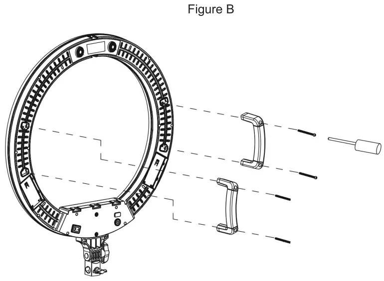
Using the Light
Mounting the Light: The R19RGB is fitted with an industry-standard 5/8″ light stand connector. This is identified as the Light Stand Mount (13) in the parts diagram. Loosen the Light Stand Connection Knob (12) before sliding the Light Stand Mount (13) onto a light stand or grip item fitted with a 5/8″ male spigot or stud. Tighten the Light Stand Connection Knob (12) for a secure fit.
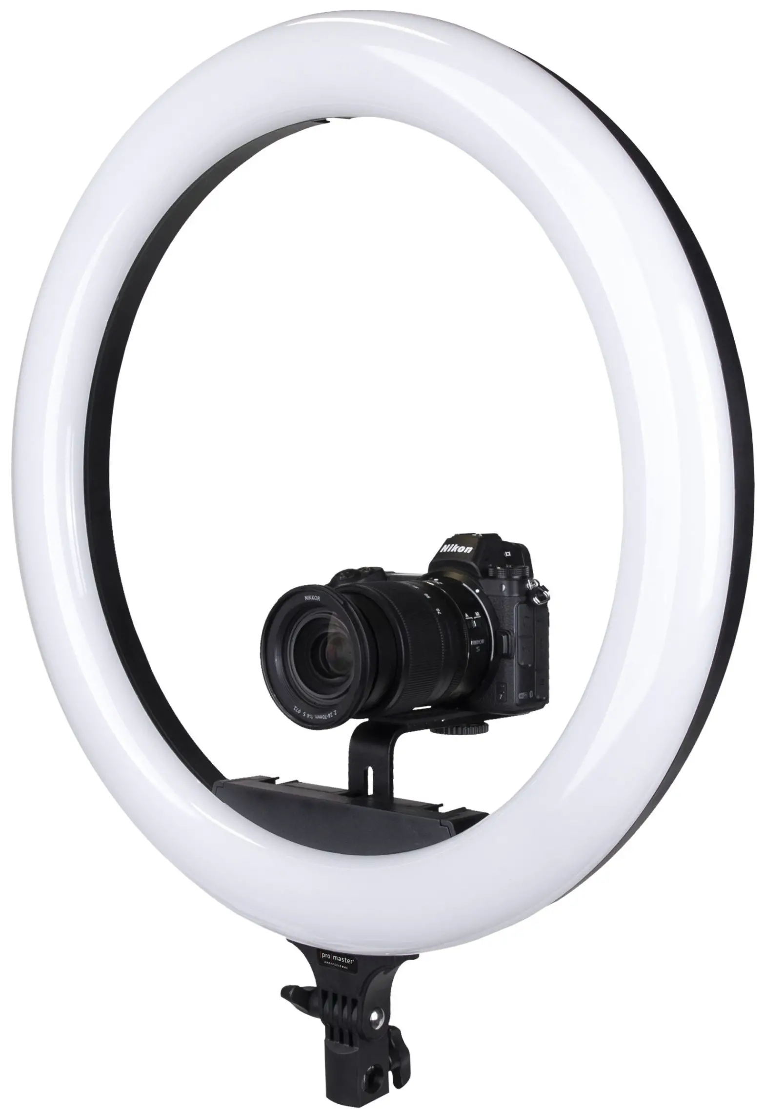
Attaching a Camera to the Light: Included with this kit are a camera connection bracket and two wing bolts. The bracket is shaped like an “L”. Align the slot in the camera connection bracket with the two Camera Bracket Connection Ports (14) on the back of the ring light. The portion of the camera connection bracket with the soft, rubber pad and attachment screw should be oriented at the top of the bracket. The bracket can be mounted in one of two directions, with the top facing into the center of the ring light or with its top facing away from the back of the ring light. Use whichever direction will give your camera the most ideal placement. Loosen the wing bolts slightly and slide the bracket up or down for the most ideal placement of your camera.
Attaching a Phone: Locate the mobile phone holder included with the kit. Slide its base into one of the Cold Shoes (1) around the light. Tighten the locking ring near the base of the mobile holder to secure it in place. Connect your phone to the holder by pulling the jaws open. These are spring-loaded. Gently lower the jaws around your phone to hold it in place. You can use the tension knob on the side of the phone holder to control its tilt for the best positioning of your phone.
Using the USB power port: The R19RGB is fitted with a USB-A Output Port (7) to supply power to a smartphone during use. This is a useful option for extended runtime. This port supplies a standard 5 volts with a maximum amperage of 2.0. I can be used whether the R19RGB is being powered by AC or batteries. However, when using this USB port with batteries, the runtime of the light will be diminished. The USB-A Output Port (7) will only supply power while the light is switched ON.
Using the Light
Powering Up and Down: The R19RGB can be powered by AC current from a common wall outlet or by two NP-F-type batteries (not included).
– llsinn AC Power Locate the AC cables included with the kit (one cable has a transformer on one end). Check to be sure the Battery / AC / OFF switch (9) is set to the OFF position (in the middle) before connecting the AC cord. Attach the figure-8 side of the power cable to the port in the transformer (the transformer is the block with a cable coming out of it). With both cables connected to each other and the transformer in the middle, connect the small, round, barrel-style end of the power cable to the back of the ringlight using its AC Cable Input Socket (8). Connect the other end of the
power cable to a common, household outlet. With the power cable completely connected you can press the Battery / AC I OFF switch (9) to the right to power the light ON. This position is identified by two vertical lines “II” on the right side of the switch and also by the word “ADAPTER” near this side of the switch.
Using Battery Power: You will need two NP-F-type batteries for this task. We are recom-
mend using batteries with at least a 4,000mAh of capacity (each). Be sure the batteries are of the same brand, age, and capacity. Charge the batteries using an external charger (not included). Be sure the Battery / AC / OFF switch (9) is set to the OFF position (in the center) before connecting any batteries. Next, align one battery at a time with either of the Optional Battery Locations (6). Notice the contact pins in these slots and orient each battery to connect with them. Start with the battery at the upper end of the slot and hold it against the back of the slot before pressing down to make full contact with the pins. Once both batteries are properly installed push the Battery / AC / OFF Switch (9) to the left, which is the battery power position. This position is identified by one vertical line “I” on the left side of the switch and also by the word “BATTERY”. Be advised you cannot charge batteries in the light. An external charger is required for charging the batteries.
Note: Always be sure the light is turned OFF and any accessory is disconnected from the USB-A Output Port before connecting or disconnecting the AC cable or batteries. Disconnect the AC cable from the household outlet BEFORE disconnecting it from the light.
CCT Mode: CCT, or Correlated Color Temperature, is a bi-color mode allowing you to change the warmth and coolness of the ringlight using the Kelvin color temperature scale. While using this mode the light will always be a “white” light, meaning you cannot apply a color. In CCT mode you can adjust the warmth and coolness of this white light similar to how sunlight changes from warm to cool and back throughout the day. The range of color temperature in this mode is 3,200K (warmest setting) to 5,600K (coolest setting).
Using the Light
Use the DIM/MODE/CH Dial (4) to enter CCT mode. Press and release this dial to change the mode between CCT and RGB. Each time you press and release this dial it will change from one to the other. Do not hold the dial pushed-in or the light will change to Channel mode. You will know you are in CCT mode when you see a 4-digit number followed the letter “K” appear on the LCD screen. This number is the indication of your color temperature. To the right will appear a 2 or 3-digit number followed by a percent “%” sign. This is an indication of the light’s brightness on a scale of 10 —100%. While in CCT mode, turn the CCT/HUE/SAT/FX Dial (3) back and forth to adjust the color temperature. Turn the DIM/MODE/CH Dial (4) back and forth to adjust the brightness.
RGB Mode: RGB is the light’s color mode. Here you have access to 360 distinct colors (hues). Each color has a corresponding number which is displayed in the LCD Display (2). You can adjust the saturation and the intensity of the color once it is selected.
Use the DIM/MODE/CH Dial (4) to enter RGB mode. Press and release this dial to change the mode between CCT and RGB. Each time you press and release this dial it will change from one to the other. Do not hold the dial pushed-in or the light will change to Channel mode. You will know you are in RGB mode when you see HUE and SAT appear on the LCD Display. HUE is an indication of the color that the light is emitting.
To change the HUE, rotate the CCT/HUE/SAT/FX Dial (3). Clockwise increases the number and counterclockwise decreases the number. When you reach 0 or 360 and go beyond either of those numbers the scale will start over. For example, going down the scale from 3 to 2 to 1 to 0, the next number will be 360. And going up the scale from 358 to 359 to 360 the next number will be 0.
To change the saturation, of a particular HUE, first, select the HUE and then press and release the CCT/HUE/SAT/FX Dial (3) once. Now rotate this same dial and the SAT number will change. Rotate the dial clockwise to increase the saturation or counterclockwise to decrease it. The scale is 0 —100%. When you reach either end of the scale the number to indicate saturation will stop.
To change the brightness of the light, rotate the DIM/MODE/CH Dial (4). Rotate this dial clockwise to increase the brightness or counterclockwise to decrease it. The scale is 10 -100% and the number will stop at either end of the scale.
Scene Mode: This mode is used for creating special effects. These effects are mostly useful for videography since they involve flashing and/or changing of the light’s intensity and color. There are 10 scenes to choose from and each has a unique number. 5 of these are accessed from CCT mode and involve effects to white light while the other 5 are accessed from the light’s RGB mode and involve effects to color. Let’s explore further.
Using the Light
With the R19RGB in CCT mode, hold down the CCT/HUE/SAT/FX Dial (3) for at least one second until the light enters scene mode. You will notice a letter “F” appear near the bottom, left of the LCD Display (2). The F-number indicates the particular scene. These are:
Fl Paparazzi F2 Fireworks F3 Faulty bulb F4 Lightning Flash F5 TV
Or, from RGB mode, hold down the CCT/HUE/SAT/FX Dial (3) for at least one second for these color scenes:
Fl Alarm lamp F2 Colors circulation F3 SOS F4 KTV F5 Fire
While in the scene mode, the stand-alone number, a few spaces to the right of the F-number indicates the speed at which the effect operates. It is a scale of 1 to 9 with 1 being the slowest and 9 being the fastest. To change the speed press and release the CCT/HUE/SAT/FX Dial (3) to change from the F-number to the speed number. Press this dial again to return to the F-number. While in either of these settings simply rotate the CCDHUE/SAT/FX Dial (3) to adjust the number.
You can change the brightness of any scene by rotating the DIM/MODE/CH Dial (4) while in that particular scene.
Note: You can adjust the hue and saturation for any of the 5 color scenes. This must be set BEFORE entering the scene mode. First, enter RGB mode and set the hue and saturation. Then enter scene mode and choose a scene. The hue and saturation (where applicable) will remain locked into the effect from your settings in RGB mode.
Setting the Channel and Using the Remote: This ring light includes a wireless remote. A separate instruction manual is included with the light that explains the use of the remote. Here we explain how to set the wireless channel on the light.
The R19RGB has wireless channels ranging from 1 to 99. The wireless remote and the light must be set to the same channel for proper operation. By having multiple channels, you can use one remote with multiple lights. If you set each light to a different channel it is possible to use the remote to make independent changes to each light. If you have multiple lights set to the same channel, a change on the remote will affect all of the lights on that channel in the same way, simultaneously.
To set the channel on the light press and hold the DIM/MODE/CH Dial (4) for approximately 1 second, until you see the number to the right of CH blink. This indicates you can set the channel. Rotate the DIM/MODE/CH Dial (4) to change the channel number. Clockwise increases the number while counterclockwise decreases it. Quickly press and release the DIM/MODE/CH Dial (4) to exit the channel setting mode. If you do not do this, the light will self-exit channel setting mode if there are no changes after 5 seconds.
One Year Unconditional Warranty
If for any reason, this ProMaster product fails within ONE YEAR of the date of purchase, return this product to your ProMaster dealer and it will be exchanged for you at no charge. ProMaster products are guaranteed for ONE FULL YEAR against defects in workmanship and materials. If at any time after one year, your ProMaster product fails under normal use, we invite you to return it to ProMaster for evaluation.
WWW.PROMASTER.COMFAIRFIELD CT 06825Made in Chinacode 2127
[xyz-ips snippet=”download-snippet”]