Wireless Datalogging Digital MultimeterUser Manual
QM1571
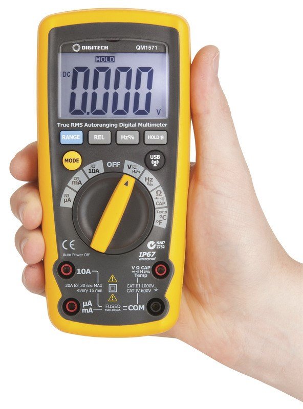
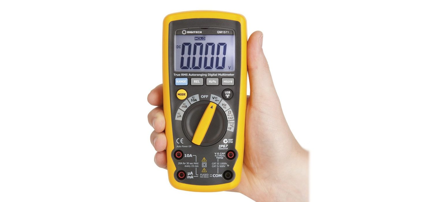
Thank you for purchasing this Wireless Data Logging Digital Multimeter. The wireless communication function of this multimeter allows you to transmit data wirelessly from the multimeter to your PC. This allows accurate recording at a much faster and detailed rate than manually writing down numbers. The true RMS function ensures accurate readings, regardless of load type or current wave shape. Packed with plenty of features, this multimeter will be your constant companion on-site, given its tough double moulded body and IP67 rating.
Please familiarise yourself with the functions of the multimeter before use. We recommend retaining this manual for ease of reference.
- Improper use of this meter can cause damage, shock, injury or death.
- Always remove the test leads before replacing the battery or fuses.
- Before using the meter, please inspect the condition of the test leads and the meter itself for any damage. If damage is present, please discontinue use.
- Do not measure voltage if the voltage on the terminals exceeds 1000V above earth ground.
- Use great care if voltages are greater than 30VAC RMS. Anything above this is considered a shock hazard.
- Always discharge capacitors and disconnect power before performing diode, resistance or continuity tests.
- Do not exceed the maximum limits of the input values shown in the specification tables on pages 12, 13, 14, 15 & 16 of this manual.
- Remove the batteries from the meter if it will be unused for an extended period of time.
- Always turn the function switch to the off position when not in use.
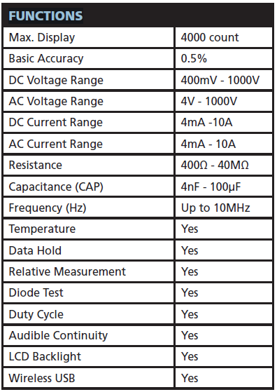
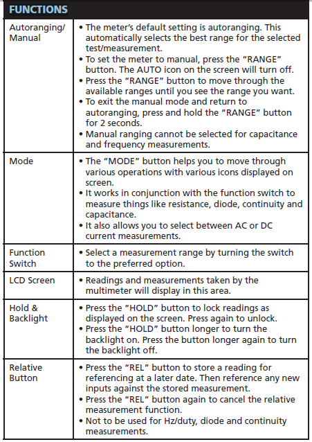
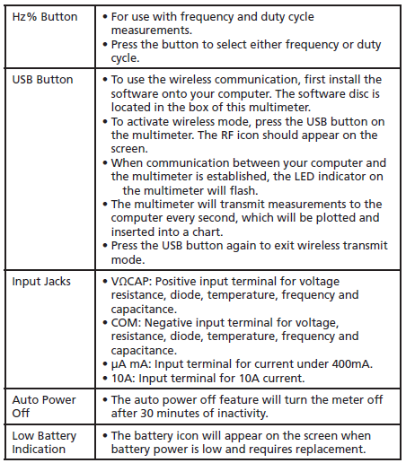
FUNCTIONS
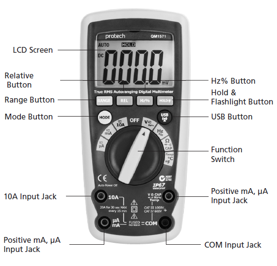
The tilt stand & battery compartment are at the rear of the multimeter.
AC/DC VOLTAGE MEASUREMENT
On some low AC and DC voltage ranges – when test leads are not connected to a device – the display on the screen may show a random, changing reading. This is normal and caused by high-input sensitivity of the multimeter. When connected to a circuit, the multimeter will display a stabilised, accurate measurement.
- Set the function switch to the VAC or VDC position.
- Insert the black test lead banana plug into the negative COM jack.
- Insert the red test lead banana plug into the positive VΩCAP jack.
- Use the Mode button to select AC or DC voltage.
- Connect the test leads in parallel to the circuit under test.
- Read the voltage in the display.
DC CURRENT MEASUREMENT
Do not measure 20A currents for longer than 30 seconds. Exceeding 30 seconds may cause damage to the meter and/or test leads.
- Insert the black test lead banana plug into the negative COM jack.• For current measurements up to 4000μA DC, set the function switch to the μA position and insert the red test lead banana plug into the μA jack.• For current measurements up to 400mA DC, set the function switch to the mA position and insert the red test lead banana plug into the mA jack.• For current measurements up to 10A DC, set the function switch to the 10A position and insert the red test lead banana plug into the 10A jack.
- Press the MODE button to show “DC” on the screen.
- Remove power from the circuit under test, then open up the circuit at the point where you wish to measure current.
- Touch the black test probe tip to the negative side of the circuit.
- Touch the red test probe tip to the positive side of the circuit.
- Apply power to the circuit.
- Read the current displayed on the screen.
AC/DC VOLTAGE MEASUREMENT
On some low AC and DC voltage ranges – when test leads are not connected to a device – the display on the screen may show a random, changing reading. This is normal and caused by high-input sensitivity of the multimeter. When connected to a circuit, the multimeter will display a stabilized, accurate measurement.
- Set the function switch to the VAC or VDC position.
- Insert the black test lead banana plug into the negative COM jack.
- Insert the red test lead banana plug into the positive VΩCAP jack.
- Use the Mode button to select AC or DC voltage.
- Connect the test leads in parallel to the circuit under test.
- Read the voltage in the display.
DC CURRENT MEASUREMENT
Do not measure 20A currents for longer than 30 seconds. Exceeding 30 seconds may cause damage to the meter and/or test leads.
- Insert the black test lead banana plug into the negative COM jack.• For current measurements up to 4000μA DC, set the function switch to the μA position and insert the red test lead banana plug into the μA jack.• For current measurements up to 400mA DC, set the function switch to the mA position and insert the red test lead banana plug into the mA jack.• For current measurements up to 10A DC, set the function switch to the 10A position and insert the red test lead banana plug into the 10A jack.
- Press the MODE button to show “DC” on the screen.
- Remove power from the circuit under test, then open up the circuit at the point where you wish to measure current.
- Touch the black test probe tip to the negative side of the circuit.
- Touch the red test probe tip to the positive side of the circuit.
- Apply power to the circuit.
- Read the current displayed on the screen.
AC CURRENT MEASUREMENT
Do not measure 20A currents for longer than 30 seconds. Exceeding 30 seconds may cause damage to the meter and/or test leads.
- Insert the black test lead banana plug into the negative COM jack.• For current measurements up to 10A, set the function switch to the 10A position and insert the red test lead banana plug into the 10A jack.• For current measurements up to 400mA, set the function switch to the mA position and insert the red test lead banana plug into the mA jack.• For current measurements up to 4000μA, set the function switch to the μA position and insert the red test lead banana plug into the μA jack.
- Press the MODE button to indicate “AC” on the screen.
- Remove power from the circuit under test, then open up the circuit at the point where you wish to measure current.
- Touch the black test probe tip to the negative side of the circuit. Touch the red test probe tip to the positive side of the circuit.
- Apply power to the circuit.
- Read the current displayed on the screen.
RESISTANCE MEASUREMENT
To avoid electric shock, disconnect power to the test area and discharge all capacitors before taking any resistance measurements. Remove the batteries and unplug the line cords.
- Set the function switch to the Ω
 CAP position.
 - Insert the black test lead banana plug into the negative COM jack.
- Insert the red test lead banana plug into the positive Ω jack.
- Press the MODE button until “Ω” displays on the screen.
- Touch the test probe tips across the circuit or part being tested. It is best to disconnect one side of the part being tested so the rest of the circuit will not interfere with the resistance reading.
- Read the resistance displayed on the screen.
CONTINUITY CHECK
To avoid electric shock, never measure continuity on circuits or wires that have voltage on them.
- Set the function switch to the Ω CAP position.
- Insert the black test lead banana plug into the negative COM jack.
- Insert the red test lead banana plug into the positive VΩCAP jack.
- Press the MODE button until displays on the screen.
- Touch the test probe tips across the circuit or wire you want to check.
- If the resistance is less than approximately 35Ω, the audible signal will sound.
DIODE TEST
The value that displays on screen during the diode check is the forward voltage.
- Set the function switch to the Ω CAP position.
- Insert the black test lead banana plug into the negative COM jack.
- Insert the red test lead banana plug into the positive VΩCAP jack.
- Press the MODE button until display on the screen.
- Touch the test probes to the diode or semiconductor being tested.
- Reverse the probe polarity by switching probe position. Note this reading.
- The diode or junction can be evaluated as follows:A) If one reading shows a value and the other reading shows OL, the diode is good.B) If both readings show OL, the device is open.C) If both readings are very small or zero, the device is shorted.
CAPACITANCE MEASUREMENTS
To avoid electric shock, disconnect power to the area being tested and discharge all capacitors before taking any capacitance measurements.
- Set the function switch to the Ω CAP position.
- Insert the black test lead banana plug into the negative COM jack.
- Insert the red test lead banana plug into the positive VΩCAP jack.
- Press the MODE button until “nF” displays on the screen.
- Touch the test leads to the capacitor being tested.
- The test may take up to three minutes or more for large capacitors to charge. Wait until the readings settle before ending the test.
- Read the capacitance value displayed on the screen.
TEMPERATURE MEASUREMENTS
The temperature probe is fitted with a type K mini connector. A mini connector to banana connector adaptor is supplied for connection to the input banana jacks.
- Set the function switch to the temp position.
- Insert the temperature probe into the input jacks, making sure to observe the correct polarity.
- Press the MODE button to indicate “ºF” or “ºC”.
- Touch the temperature probe head to the part you wish to measure. Ensure the probe remains in contact with the part until the reading stabilises (about 30 seconds).
- Read the temperature displayed on the screen.
FREQUENCY MEASUREMENT
- Set the function switch to the HZ% position.
- Insert the black test lead banana plug into the negative COM jack.
- Insert the red test lead banana plug into the negative VΩCAP jack.
- Touch the test probes to the circuit being tested.
- Read the frequency displayed on the screen.
MEASUREMENT SPECIFICATIONS
The following guide is based on an environmental temperature of 18-28°C and humidity <70%.
DC VOLTAGE
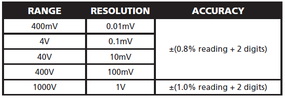
Input impedance: 10MΩ; Max. input voltage: 1000V DC
AC VOLTAGE
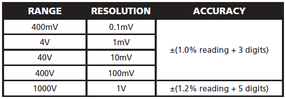
Input impedance: 10MΩ; Max. input voltage: 1000VAC RMS;Frequency range: 50~400Hz; all AC voltage ranges are specified from 5% of range to 100% of range.
DC CURRENT
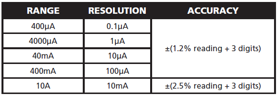
Overload protection: fuse FF500mA/1000V and fuse F10A/1000V. Maximum inputs: 400μA DC (μA range), 400mA DC (mA range), 10A DC (10A range).
AC CURRENT
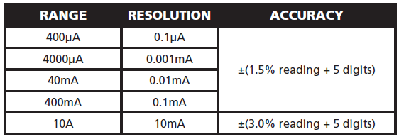
Overload protection: fuse FF500mA/1000V fuse FF10A/500V.Frequency range: 50~400Hz
RESISTANCE
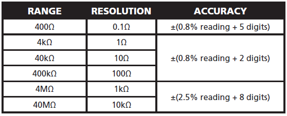
Input protection: 1000VDC or 1000VAC RMS
CAPACITANCE
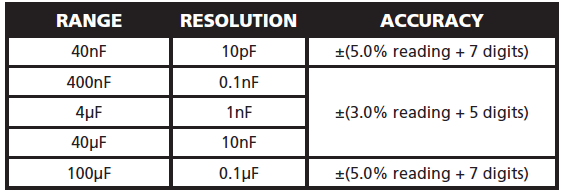
Overload protection: 1000VDC or 1000VAC RMS
DUTY CYCLE
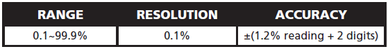
Pulse width: >100us, <100ms; Frequency width: 5Hz-150kHz.
FREQUENCY
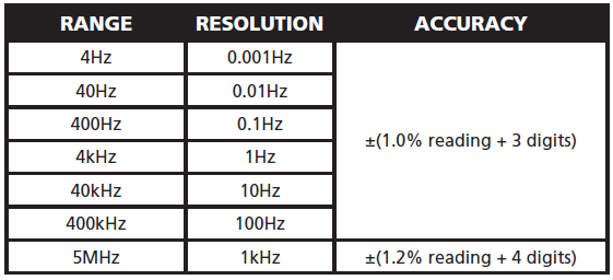
Overload protection: 1000VDC or 1000VAC RMS.Sensitivity >0.5V while ≤1MHz, >3V while >1MHz.
TEMPERATURE
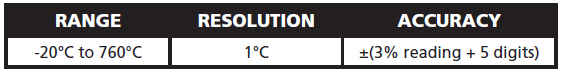
Overload protection: 1000VDC or 1000VAC RMS.
DIODE & CONTINUITY
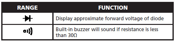
DIODE TEST
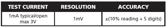
Open circuit voltage max 3V; overload protection 1000VDC or 1000VAC RMS.
AUDIBLE CONTINUITY

MAINTENANCE
BATTERY INSTALLATION
To avoid the false readings, replace the battery as soon as the low battery power indicator appears.
- Turn the power off and disconnect the test leads from the meter.
- Open the rear battery cover with a screwdriver.
- Remove the old battery and insert the new battery into the battery holder, observing the correct polarity.
- Put the battery cover back in place, secure with the screws.
REPLACING FUSES
- Turn power off and disconnect the test leads from the meter.
- Remove the battery cover.
- Gently remove the old fuse and install the new fuse into the holder.
- Always use a fuse of the proper size and value (0.5A/1000V fast blow for the 400mA range, 10A/1000V fast blow for the 10A range).
- Replace and secure the cover
SPECIFICATIONS
- Enclosure: Double-molded
- AC Response: TRMS
- Display: 4,000 count LCD display
- Over Range Indication: “OL” is displayed
- Auto Power: 30 min (approx)
- Polarity: Automatic (no indication for positive); minus (-) sign for negative
- Low Battery Indication: is displayed if battery voltage drops below operating voltage
- Battery: 1 x 9V
- Operating Temperature: -10°C to 50°C
- Storage Temperature: -30°C to 60°C
- Operating Humidity: <70%
- Storage Humidity: <80%
- Relative Humidity: 90% (0°C to 30°C); 75% (30°C to 40°C); 45% (40°C to 50°C)
- Operating Altitude: 3000m maximum
- Weight: 380g
- Size: 182(L) x 82(W) x 55(H)mm
BOX CONTENTS
- 1 x Multimeter
- 1 x Test Leads
- 1 x Carry Case
- 1 x 9V Battery
- 1 x User Manual
Distributed by:Electus Distribution Pty. Ltd.320 Victoria Rd, RydalmereNSW 2116 Australiawww.electusdistribution.com.auMade in China
References
[xyz-ips snippet=”download-snippet”]