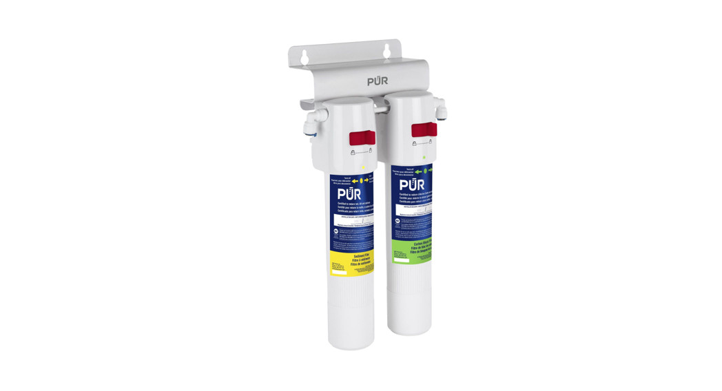
Under Sink Quick-ConnectWater Filtration Systems

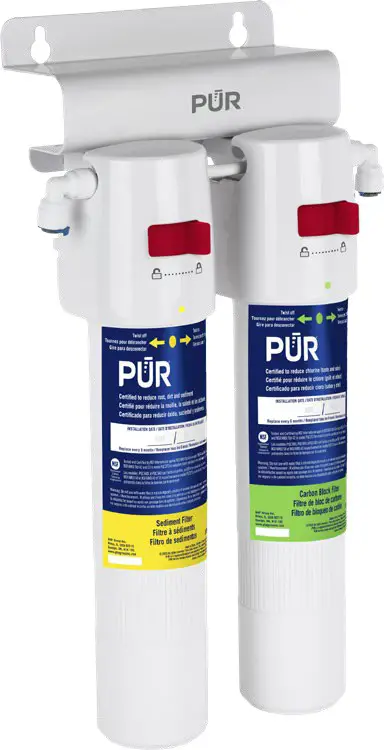 Owner’s ManualPQC1FSPQC2FS
Safety Precautions:
- You must follow the guidelines to install this system. Check with your Province/State and local public works department for plumbing and sanitation codes.
- If house water line pressure is over the maximum 100 psi (pounds per square inch), install a pressure regulator in the water supply line before this system.
- The system is for cold water use only and must be protected against freezing, which can cause water leakage.
- Do not use water that is microbiologically unsafe or of unknown quality without adequate disinfection before or after the system. Systems certified for cyst reduction may be used on disinfected water that may contain filterable cysts.
- Make sure the water supply conforms to the specification guidelines. If the water supply conditions are unknown, consult your local municipal water company or the health department about the quality and the list of contaminants of the water in your area.
- While using the system for the first time, or prolonged non-use (such as during a vacation over one week), the system should be flushed thoroughly.
- This system contains replaceable filter cartridge(s) with limited service life.
Conditions for Operation:
General ConditionsMin. / Max. Operating Pressure ……………….. 30 – 100 psi (207-689 kPa)Min. / Max. Operating Temperature ……………. 40 – 113°F (4.4-45°C)Conditions for PQC1FSFlow Rate …………………………………………………….. 1 GPM (3.8 LPM)Replacement Cartridges…………………………………. PQCCRB (Carbon Block)Capacity ……………………………………………………… 1000 Gallons (3,780 Liters)Conditions for PQC2FSFlow Rate ………………………………………………… 0.5 GPM (1.9 LPM)Replacement Cartridges……………………………… PQCCRBL (Carbon Block) and PQCSED (Sediment)Capacity ………………………………………………….. 500 Gallons (1,890 Liters)
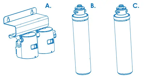
Package Contents:
PQC1FS
PQC2FS
PQC1FS
|
Item |
Description |
QTY |
| A | Head Assembly with Bracket | 1 |
| C | Carbon Block Filter (PQCCRB) | 1 |
PQC2FS
|
Item |
Description |
QTY |
| A | Head Assembly with Bracket | 1 |
| B | Sediment Filter (PQCSED) | 1 |
| C | Carbon Block Filter (PQCCRBL) | 1 |
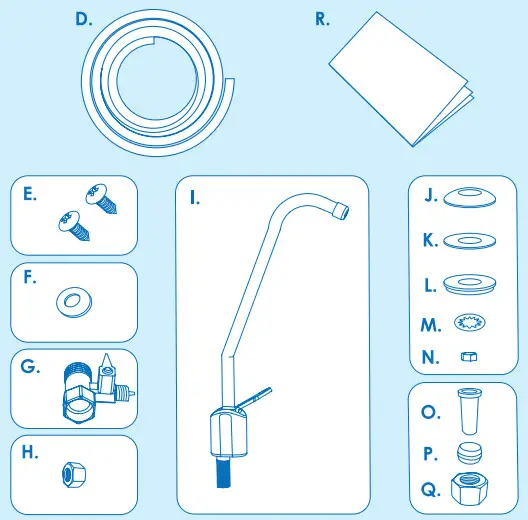
ACCESSORIES KIT
|
Item |
Description |
QTY |
| D | 6′ of 1/4″ White Tubing | 1 |
| E | Mounting Screw | 2 |
| F | Inlet Rubber Washer | 1 |
| G | Inlet Valve | 1 |
| H | Inlet Compression Nut | 1 |
| I | Faucet | 1 |
| J | Escutcheon Plate | 1 |
| K | Rubber Gasket | 1 |
| L | Plastic Lock Washer | 1 |
| M | Star Washer | 1 |
| N | Stem Nut | 1 |
| O | Plastic Insert | 1 |
| P | Plastic Ferrule | 1 |
| Q | Faucet Compression Nut | 1 |
| R | Installation, Use & Care Guide | 1 |
Tools Required for Installation:
Installation Instructions:
The filter(s) of PQC1FS and PQC2FS Systems have been pre-assembled and tested at the factory. To check or replace the filter(s), the following steps need to be implemented:
Installing the Quick-Connect Filter (See Figure 1):
- Unlock the Locking Tab by sliding it from the right to the left side of the slot to the ‘Unlock’ Position.
- Lift the filter top section into the Head. Turn the filter about 1/4 turn in the direction as shown in Figure 1 until it stops.
- Slide the Locking Tab from left to right of the slot to the ‘Lock’ position.
Figure 1.
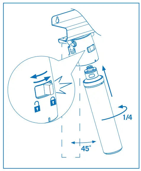
Un-installing the Quick-Connect Filter (See Figure 2):
- Unlock the Locking Tab by sliding it from the right to the left of the slot to the ‘Unlock’ Position.
- Turn the filter in the direction as shown in Figure 2 about 1/4 turn until it comes out of the Head.
NOTE: The filter head can be swung forward to assist in the filter installation/removal.CAUTION: Some water will drip during filter removal so use a tray to catch any spillage.CAUTION: Do not attempt to turn the filter housing while in the ‘Lock’ position. It may damage the system and cause leaks.
Figure 2.
Connecting to Cold Water Line (See Figure 3 and 4):
CAUTION: The water supply to your unit MUST be from the COLD WATER LINE. Hot water will damage your filtration system.
- Turn off the cold water supply under the sink by turning the valve to the off position. If the cold water line does not have a shut-off valve under the sink, turn off the main water line in the house. Place a tray or towel under the cold water line to catch any excess water.
- Turn on the cold water faucet and allow all the water to drain from the line. On a single-handle faucet, the hot water may have to be turned off to prevent any hot water cross over.
- Loosen nut and separate cold water braided flex line from the kitchen cold water faucet shank. Attach Inlet Valve to the faucet shank using the Rubber Washer. Reinstall the flex line onto the Inlet Valve and tighten with an adjustable wrench.
- Insert 1/4” White Tubing over the Guide Tube of the Inlet Valve. Tighten the Compression Nut with an adjustable wrench.
Figure 3
Figure 4
Drilling the Faucet Hole (See Figure 5):
The Drinking Water Faucet should be positioned with function, convenience and appearance in mind. An adequate flat area is required to allow Faucet to rest securely. Check the underside of the location for interference. Most sinks have a pre-drilled 1-1/4″ diameter hole designed for spray hoses. The Drinking Water Faucet may be installed using this hole. If the pre-drilled hole cannot be used, or is in an inconvenient location, it will be necessary to drill a minimum 5/8” hole in the sink or through the countertop next to the sink for the Faucet.
CAUTION: Do not drill through a countertop that is more than 1” thick.CAUTION: Do not attempt to drill through a tiled, marble, granite or similar countertop. Consult a plumber or the countertop manufacturer for advice or assistance.CAUTION: When drilling through a countertop make sure the area below the drilling area is free of wiring and piping. Make certain that you have ample room to zmake the proper connection to the bottom of the Faucet.CAUTION: Do not attempt to drill through an all-porcelain or porcelain-coated sink. For applications on these types of sinks, we recommend using the sprayer hole or mounting the Faucet through the countertop. Otherwise, consult a plumber or manufacturer for advice or assistance.
- Line the bottom of the sink with newspaper to prevent shavings, parts or tools from falling down the drain.
- Place masking tape over the area to be drilled to help prevent scratches if drill bit slips.
- Mark point with a center punch. Use a 5/8” drill bit to drill a hole.
- Smooth rough edges with a file.
Figure 5

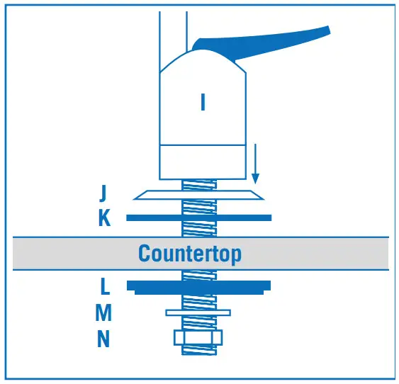
Installing the Faucet (See Figure 6):
- Guide Escutcheon Plate (J) and Rubber Gasket (K) onto the stem of Faucet (I). Slip the stem into the hole and make sure it sits flat on the top of the sink or countertop surface.
- From underneath the sink, slide Plastic Lock Washer (L) and Star Washer (M) up along the stem, then screw Stem Nut (N) all the way up the stem until it is flush with the Star Washer. Tighten with an adjustable wrench until it is slightly snug and check to make sure the Faucet spout is in the proper position.
Figure 6
Mounting the System under the Sink (See Figure 7):
- Choose an easy-to-access area under the sink to mount the system.Note: Mount the system to a solid cabinet wall. If a solid wall is not available, use hollow-wall anchor bolts or toggle bolts (not included) to secure to the wall.
- Use the Pre-assembled Head Assembly (A) as a template, mark the holes for positioning the system on the wall surface.
- Insert Mounting Screws (E) into the wall with a Phillips screwdriver, leaving approximately 3/8” of each screw exposed. Hang the system through the eyes of the bracket on the screws. Tighten the screws to secure the system.
- Leave 1″ clearance below the filters to ensure there is no interference when replacing them.
Figure 7
Connecting Tubing from Water Line to System (See Figure 7):
- Determine the length of 1/4” Tubing (D) from Inlet Valve (G) to the Inlet of Head Assembly (A) by holding Tubing in place ensuring it is of appropriate length. Cut the Tubing square with a utility knife.CAUTION: Do not kink Tubing as this will impede water flow.
- Wet one end of the Tubing with water and push it onto the guide tube of the valve until it stops.
- Hand-screw the Inlet Compression Nut (H) on the valve and tighten with an adjustable wrench.
- Push another end of the Tubing into the Inlet of Head Assembly (A) by referring to the instructions of “Tubing Connection with Quick-Connect Fittings.”
Connecting Tubing from System to Faucet (See Figure 7):
- Determine the length of 1/4” Tubing (D) from the outlet of Head Assembly (A) to the stem of the Faucet by holding Tubing in place ensuring it is of appropriate length. Cut the Tubing square with a utility knife.CAUTION: Do not kink Tubing as this will impede water flow.
- Gently slide Faucet Compression Nut (Q) down over the Tubing. Follow with Ferrule (P). Push Insert (O) into the end of the Tubing.
- Firmly push the Tubing into the stem of Faucet until it stops. Hand-screw the Nut onto the threads of the stem. Tighten with wrench.CAUTION: Do not overtighten the Compression Nut.
- Push another end of the Tubing into the water outlet of Head Assembly (A) by referring to the instructions of “Tubing Connection with Quick-Connect Fittings.”
Connecting the Tubes Using Quick-Connect Fittings (See Figure 8, 9 and 10):
- Remove the blue Horseshoe Clip from Collet. (Figure 8)
- Pull out and discard the protect plug by pushing the Collet inward and holding with fingers. (Figure 9)
- Insert Tubing into the Collet. Full engagement is 11/16” length of the Tubing into the fitting. (Figure 10)NOTE: Ensure Tubing is pushed all the way to backstop.
- Put blue Horseshoe Clip back on Collet.
Start-up Instructions:
- Turn Inlet Valve (G) to open position and the cold water sink Faucet to the closed position. (Figure 7)
- Slowly open the cold water supply valve that you closed at the beginning of this installation.
- Open Faucet (I) to purge air from the system. When the water runs smooth with no bubbles or spurting, close the Faucet and check for leaks for all fittings.
- Open the Faucet (I) again to rinse the system.CAUTION: Let water run 15 minutes before using.NOTE: Initially, there may be some dark discoloration of the water (carbon deposits). This condition is normal and will disappear quickly.
Periodic System Maintenance:
Depending on which model was purchased, the chart below will assist with replacement of filters. The replacement filter can be obtained online at www.ghpgroupinc.com or at the retail store where the system was purchased.
| Model # | Filter Replacement Kit – Replace every 6 months |
| PQC1FS | PQCCRBKIT (contains: 2x PQCCRB) |
| PQC2FS | PQC2FSKIT (contains: 1x PQCCRBL, 1x PQCSED) |
Filter Cartridge Replacement Instructions:
Filters must be replaced periodically. Refer to the replacement schedule above.
- Turn off Inlet Valve (G), and open Faucet (I) to relieve pressure from the system. Place a tray or towel under Filter Housing (B and C) to catch excess water.To replace filter for PQC1FS:
- Follow the instruction of “Un-installing the Quick-Connect Filter” on Page 3 to remove old filter.
- Then, follow the instruction of “Installing the Quick-Connect Filter” on Page 3 to install new filter. Then go to step 5 below.To replace filter for PQC2FS:
- Follow the instruction of “Un-installing the Quick-Connect Filter” on Page 3 to remove old filters.
- Then, follow the instruction of “Installing the Quick-Connect Filter” on Page 3 to install new filters.
- Make sure Sediment Filter (B, yellow dot) is installed to Inlet side of the system and Carbon Block Filter (C, green dot) is to outlet side of the system. Then go to step 5 below.CAUTION: When looking at the system from the front, the Sediment Filter must be on the left and Carbon Block Filter must be on the right.
- Slowly open Inlet Valve (G) that you turned off at the beginning of this instruction.
- Open the Faucet (I) to purge air from the system. When the water runs smooth with no bubbles or spurting, close the Faucet and check for leaks. If any leaks, re-install the housing as needed.
- Open the Faucet (I) again to rinse the system.CAUTION: Let water run 15 minutes before using.NOTE: Changes in taste, odor, color and/or flow of the filtered water may indicate that the cartridge should be replaced.
Troubleshooting Guide:
|
Problem |
Possible Cause |
Solution |
|
Water leaks between sump and head |
Loose connection of sump and head | Unlock the filter head assembly and re-install the housing. |
| O-rings missed or not in right position | Open sump to check the O-rings. | |
| Water leaks at push-in connections | Tubing is not pushing in all the way | Push tubing in as far as it will go. |
| Tubing end is not cut square | Push tubing out and recut to square. | |
| Tubing is cracked or scratched | Simply cut that portion away and reinsert tubing. | |
| Water leaks at threaded fittings | Loose connection | Tighten slightly more until leak stops. Do not over-tighten. |
| Water has air bubbles and is cloudy | Air in the system after installation | Will go away after water runs for a while. |
| Water leak at thread fittings | Fitting not tightened | Tighten fittings as necessary. |
| Either no water flow or very slow | Inlet valve is closed | Turn on the valve. |
| Filter cartridge has become clogged | Replace the filter cartridge. | |
| Tubing is kinked | Check the tubing and make smooth line. | |
| Water tastes bad or has an odor | The filter is expended | Replace the filter cartridge. |
Should service be required or you have any questions regarding how to use your PUR product, please contact Customer Service at: 1-877-447-4768 or [email protected]
Performance Data Sheet:
Note: Read this performance data and compare the capability of this system with your actual water treatment needs. It is recommended that, before installing the system, you have your water supply tested to determine your actual water treatment needs.These systems conform to NSF/ANSI 53 and/or 42 for the specific performance claims as verified and substantiated by test data. While testing was performed under standard laboratory conditions, actual performance may vary.The PQC1FS system has been certified by NSF International according to NSF/ANSI 42 and CSA B483.1. The PQC2FS system has been certified by NSF International according to NSF/ANSI 42, 53 and CSA B483.1 for the reduction of substances listed below. The concentration of the indicated substances in water entering the system was reduced to a concentration less than or equal to the permissible limit for water leaving the system as specified in NSF/ANSI 42 and 53.
PQC1FS with PQCCRB Filter
|
Substance |
Average Influent Challenge Concentration | Percent ReductionRequirement |
Percent Reduction1 |
| NSF Standard 42 | |||
| Chlorine | 2.0 mg/L ± 10% | ≥ 50% | 91.8% |
| Particulate Class III | 10,000/mL | ≥ 85% | 99.9% |
Flow Rate =1 gpm (3.78 lpm)Capacity = 1,000 gallons (3,780 L) or 6 months
PQC2FS with PQCSED and PQCCRBL Filters
|
Substance |
Average InfluentChallenge Concentration | Percent ReductionRequirement |
Percent Reduction1 |
| NSF Standard 42/53 | |||
| Chlorine | 2.0 mg/L ± 10% | ≥ 50% | 97.4% |
| Particulate Class I | 10,000/mL | ≥ 85% | 99.6% |
| pH 8.5 | 0.15 mg/L± 10% | 0.010mg/L | 99.7% |
| pH 6.5 | 99.7% | ||
| Cyst | ≥ 50,000 /mL | ≥ 99.95% | 99.99% |
Flow Rate = 0.5 gpm (1.9 lpm)Capacity = 500 gallons (1,890 L) or 6 months
- Tested by NSF International according to NSF/ANSI Standard 42, 53 and CSA B483.1.
Manufactured and warranted by GHP Group Inc.USA: 6440 W. Howard St. Niles, IL 60714-3302Canada: 271 Massey Rd. Guelph, Ontario, N1K 1B2
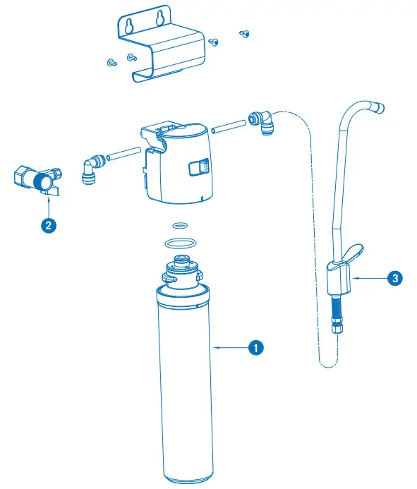
Replacement Parts List:
PQC1FS
|
Item |
Description |
Part # |
| 1 | Carbon Block Cartridge | PQCCRB |
| 2 | Inlet Valve | VWC10001 |
| 3 | Faucet | VWC10002 |
Replacement Parts List:
PQC2FS
|
Item |
Description |
Part # |
| 1 | Sediment Cartridge | PQCSED |
| 2 | Carbon Block Cartridge | PQCCRBL |
| 3 | Inlet Valve | VWC10001 |
| 4 | Faucet | VWC10002 |
Warranty:
Limited Warranty:This limited warranty is extended to the original retail purchaser of this filtration system and warrants against any defect in material and workmanship for a period of one (1) year from the date of retail sale. GHP Group, Inc., at its option, will either provide replacement parts or replace the unit, when properly returned to the retailer where purchased within one (1) year of retail purchase. (Shipping costs, labor costs, etc. are the responsibility of the purchaser.)Duties of the Owner:This filtration system must be installed and operated in accordance with the written instructions furnished with this system. This warranty shall not excuse the owner from properly maintaining this unit in accordance with the instructions. A bill of sale, canceled check or payment record must be kept to verify purchase date and establish a warranty period. Original carton should be kept in case of warranty return of the unit.
What is Not Covered?
- Damage caused by misuse, installation or use contrary to the owner’s manual and safety guidelines.
- Use of this product where water is microbiologically unsafe or of unknown quality.
- Damage caused by a lack of normal maintenance and cleaning.
- Use of non-OEM parts or accessories.
- Damage caused in transit. Freight charges on warranty parts or products to and from the factory shall be the responsibility of the owner.
THIS LIMITED WARRANTY IS GIVEN TO THE PURCHASER IN LIEU OF ALL OTHER WARRANTIES, EXPRESSED OR IMPLIED, INCLUDING BUT NOT LIMITED TO THE WARRANTIES OF MERCHANTABILITY OF FITNESS FOR A PARTICULAR PURPOSE. THE REMEDY PROVIDED IN THIS WARRANTY IS EXCLUSIVE AND IS GRANTED IN LIEU OF ALL OTHER REMEDIES. IN NO EVENT WILL GHP GROUP. INC. BE LIABLE FOR INCIDENTAL OR CONSEQUENTIAL DAMAGES.Some states/provinces do not allow limitations on how long an implied warranty lasts, so the above limitation may not apply to you. Some states/provinces do not allow the exclusion or limitation of incidental or consequential damages so the above limitation or exclusion may not apply to you.
Claims Handled as Follows:
- Contact your retailer and explain the problem.
- If the retailer is unable to resolve the problem, contact our Customer Service Dept. detailing the system model, the problem, and proof of date of purchase.
- A representative will contact you. DO NOT RETURN THE UNIT TO GHP GROUP, INC. unless instructed by our Representative, or with written authorization.
report this adThis warranty gives you specific legal rights and you may also have other rights that vary from state/province to state/province.Product Registration:To Register your product, please visit: ghpgroupinc.com/product-registration.html and complete within (14) days of purchase.
References
[xyz-ips snippet=”download-snippet”]