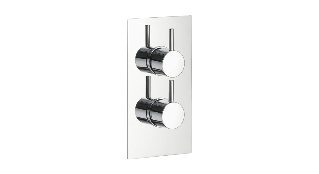

TWIN & TRIPLE CONTROL CONCEALED THERMOSTATICSHOWER VALVE INSTALLATION & OPERATING GUIDE
- We recommend this product is installed by a qualified professional contractor, such as a plumber who is certified by NVQ(National Vocational Qualification) or SNVQ (Scottish National Vocational Qualification) Level 3. All valves should be installed in accordance with the water bye-laws. For further details, refer to the latest copy of the Water Bye-laws guide or your local water authority.
- Please check the product immediately to ensure it has not been damaged and is complete. Before installation, please make sure this product is the correct model and you have all the parts required for installation and use.
- All valves should be supplied with hot and cold water at balanced pressure. If not, the mixing function will not work correctly. It is necessary to fit non-return valves on both hot and cold feed pipes.
- Please flush the water system to ensure that no metal swarf, solder, and other impurities can enter the valves.5. Turn off the water supply before commencing installation. This should be done at the isolating valves of inlet feeds if fitted or the main stopcock.
- Please read these instructions carefully and retain them for future

TECHNICAL DATA
- Cold Supply Temperature: 4-29°C; Hot Supply Temperature: 55-58°C;
- Thermostatic Temperature Range: 20-50°C.
- Pre-set Temperature: 38°C.
- Safety Mechanism: The mixed water will be immediately cut off when the cold supply is not effective.
- Precise Temperature: It takes approximately 5 seconds to achieve the desired temperature. The actual working temperature will be within ±2°C of the temperature.
- Temperature Stability: The outlet temperature variation will be within ±2°C when the inlet temperature is stable and the hot and cold pressure varies by 50%. The outlet temperature variation will be within ±2°C when the inlet pressure is stable and the hot supply temperature increases from 60°C to 75°C (5°C/min).
- Minimum Pressure: 0.1 bar Recommend Pressure: 0.2 bar
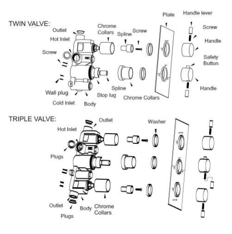
COMPONENTS
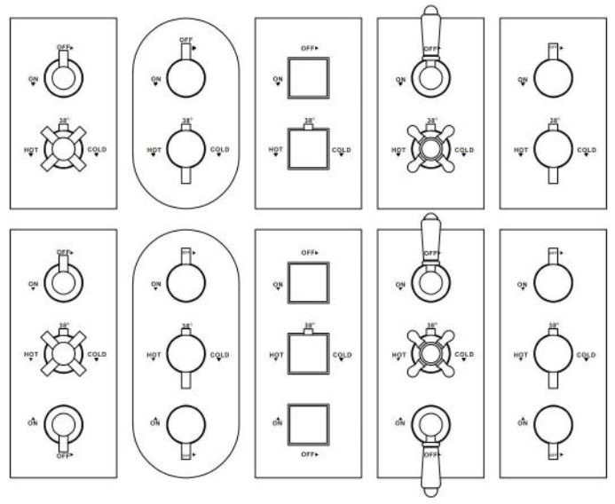
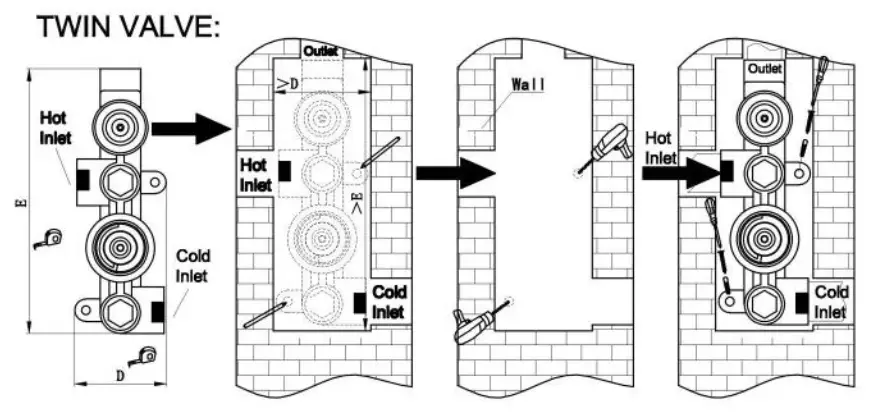
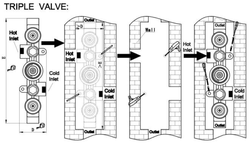
DIMENSION DRAWING

PREPARATION FOR INSTALLATION
- Carefully remove the product from the packaging to prevent scratches, wearing cotton gloves if possible.
- Identify all components.
- Prior to installation, flush out the pipework thoroughly to remove debris.
- Turn off the water supply.
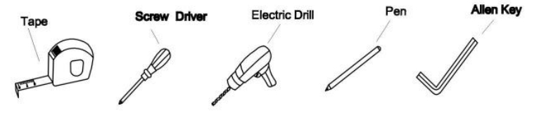
- Tools you might need:
INSTALLATION
- Determine the fixing position for the valve. Make a recess in the wall according to the dimensions of the shower valve and mark the required installation holes and sizes. Drill the holes with plastic plugs. Connect the inlet and outlet to the correct pipework with the necessary sealant. Screw the shower valve body into position, using the mounting lugs that are cast into the base of the body.
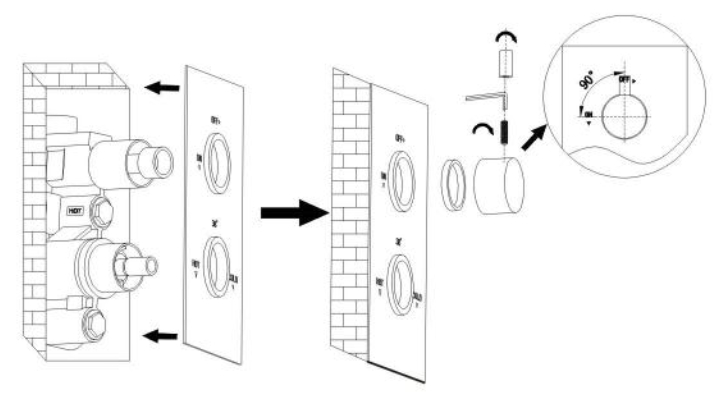
- Secure the concealing plate onto the valve body which is dearly marked. Then fit the rubber washer. handle body, grub screw, and hand lever.
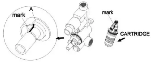
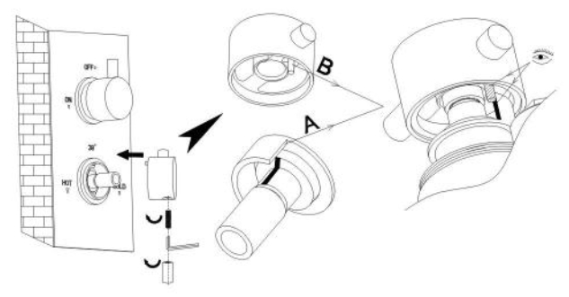
- The factory outlet temperature setting is 38°C when face ‘N is aligned with the mark on the cartridge. Do not turn the spindle in case movement occurs which will result in an incorrect factory outlet temperature setting. If this is the case. please re-align as shown below.
- Fit the stop lug and handle body with parlA and B (fix stopper) aligned.
- Your shower valve is now ready for use.CLEANINGThis product is made using high-quality chrome plating which should be maintained using a clean, damp cloth. No abrasive agents or materials can be used. The use of these agents will invalidate your guarantee.
 CLEANINGThis product is made using high-quality chrome plating which should be maintained using a clean, damp cloth. No abrasive agents or materials can be used. The use of these agents will invalidate your guarantee.
[xyz-ips snippet=”download-snippet”]