PURE RESONANCE AUDIO RZMA120BT Zone Mixer Amplifier User Manual
INSTALLATION AND OPERATION MANUAL
 Caution: Please read this manual carefully before operating. Damage caused by misuse is not covered by the warranty.
SAFETY PRECAUTIONS
- Be sure to read the instructions in this section carefully before use.
- Make sure to observe the instructions in this manual as the conventions of safety symbols and messages regarded as very important precautions are included.
- We also recommend you keep this instruction manual handy for future reference.
SAFETY SYMBOL AND MESSAGE CONVENTIONS
Safety symbols and messages described below are used in this manual to prevent bodily injury and property damage which could result from mishandling. Before operating your product, read this manual first and understand the safety symbols and messages so you are thoroughly aware of the potential safety
![]() Indicates a potentially hazardous situation which, if mishandled, could result in death or serious personal injury.
Indicates a potentially hazardous situation which, if mishandled, could result in death or serious personal injury.![]() Indicates a potentially hazardous situation which, if mishandled, could result in moderate or minor personal injury, and/or property damage.
Indicates a potentially hazardous situation which, if mishandled, could result in moderate or minor personal injury, and/or property damage.

WHEN INSTALLING THE UNIT
- Do not expose the unit to rain or an environment where it may be splashed by water or other liquids, as doing so may result in fire or electric shock.
- Use the unit only with the voltage specified on the unit. Using a voltage higher than that which is specified may result in fire or electric shock.
- Do not cut, kink, otherwise damage nor modify the power supply cord. In addition, avoid using the power cord in close proximity to heaters, and never place heavy objects — including the unit itself — on the power cord, as doing so may result in fire or electric shock.
- Be sure to replace the unit’s terminal cover after connection completion. Because high voltage is applied to the speaker terminals, never touch these terminals to avoid electric shock.
- Be sure to ground to the safety ground (earth) terminal to avoid electric shock. Never ground to a gas pipe as a catastrophic disaster may result.
- Avoid installing or mounting the unit in unstable locations, such as on a rickety table or a slanted surface. Doing so may result in the unit falling down, causing personal injury and/or property damage.
WHEN THE UNIT IS IN USE
- Should the following irregularity be found during use, immediately switch off the power, disconnect the power supply plug from the AC outlet and contact your nearest dealer. Make no further attempt to operate the unit in this condition as this may cause fire or electric shock.• If you detect smoke or a strange smell coming from the unit.• If water or any metallic object gets into the unit• If the unit falls, or the unit case breaks• If the power supply cord is damaged (exposure of the core, disconnection, etc.)• If it is malfunctioning (no tone sounds.)
- To prevent a fire or electric shock, never open nor remove the unit case as there are high voltage components inside the unit. Refer all servicing to your nearest dealer.
- Do not place cups, bowls, or other containers of liquid or metallic objects on top of the unit. If they accidentally spill into the unit, this may cause a fire or electric shock.
- Do not insert nor drop metallic objects or flammable materials in the ventilation slots of the unit’s cover, as this may result in fire or electric shock.

WHEN INSTALLING THE UNIT
- Never plug in nor remove the power supply plug with wet hands, as doing so may cause electric shock.
- When unplugging the power supply cord, be sure to grasp the power supply plug; never pull on the cord itself. Operating the unit with a damaged power supply cord may cause a fire or electric shock.
- When moving the unit, be sure to remove its power supply cord from the wall outlet. Moving the unit with the power cord connected to the outlet may cause damage to the power cord, resulting in fire or electric shock. When removing the power cord, be sure to hold its plug to pull.
- Do not block the ventilation slots in the unit’s cover. Doing so may cause heat to build up inside the unit and result in fire.
- Avoid installing the unit in humid or dusty locations, in locations exposed to the direct sunlight, near the heaters, or in locations generating sooty smoke or steam as doing otherwise may result in fire or electric shock.
WHEN THE UNIT IS IN USE
- Do not place heavy objects on the unit as this may cause it to fall or break which may result in personal injury and/or property damage. In addition, the object itself may fall off and cause injury and/or damage.
- Make sure that the volume control is set to minimum position before power is switched on. Loud noise produced at high volume when power is switched on can impair hearing.
- Do not operate the unit for an extended period of time with the sound distorting. This is an indication of a malfunction, which in turn can cause heat to generate and result in a fire.
- Contact your dealer as to the cleaning. If dust is allowed to accumulate in the unit over a long period of time, a fire or damage to the unit may result.
- If dust accumulates on the power supply plug or in the wall AC outlet, a fire may result. Clean it periodically. In addition, insert the plug in the wall outlet securely.
- Switch off the power, and unplug the power supply plug from the AC outlet for safety purposes when cleaning or leaving the unit unused for 10 days or more. Doing otherwise may cause a fire or electric shock.
An all-pole mains switch with a contact separation of at least 3 mm in each pole shall be incorporated in the electrical installation of the building.
DESCRIPTION
The Pure Resonance Audio RZMA120BT 4 zone commercial mixer amplifier is designed with 4 ohm, 70 Volt and 100 Volt terminals and 4 x 120W power output. The RZMA12BT is a rack mount audio matrix system solution with MP3, tuner and Bluetooth. Each input can easily be designated to a different zone via the front panel selector making this mixer amplifier ideal for hotels, shopping malls, sports centers, entertainment centers, and anywhere multi-zone audio is needed.
FEATURES
- 4 channel amplifier in a 3U 19” rack mount design
- All source inputs can be matrix assigned to different 4 zones output simultaneously
- The 5 channel inputs & MP3 input are designed with separate bass, treble and volume control
- 3 microphone / line inputs with phantom power and gain control
- 2 AUX inputs by RAC with gain control
- MP3 player with SD and USB inputs has a separate power supplied module
- Built in tuner audio source
- 1 4 zone remote microphone input via RJ45 port
- 4 channel line inputs and speaker outputs
- Versatile speaker outputs for each four channels : 70V, 100V and 4 Ω
- A RS232 serial control port for third party system communication
- A priority input to override other inputs (equal to EMC input)
- Input priority level from high to low: Before short circuit priority input: MIC1 TEL Remote MIC MIC2= MIC3 = LINE4 = LINE5 = MP3 After short circuit priority input: TEL MIC1 Remote MIC MIC2 = MIC3 = LINE4 = LINE5 =MP3
- Built-in monitor with volume control
- Extensive protection of thermal, short-circuit, clip and overload with indicators
- Ground lift switch
FRONT PANEL
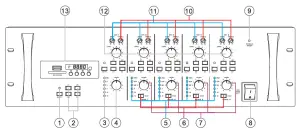
- Mute button and indicator, Mute on, indicators are on; mMute off, then indicators are off
- Amplifier matrix 4 channel selector button
- Monitor level indicator
- Monitor volume control
- 1-4 zone amplifier level indicator
- 1-4 zone monitor selector button
- 1-4 zone amplifier output volume control
- ON/OFF Power switch, Switch on, power on; Switch down, power off
- POWER-Power indicator When power on, power indicators are on; When power off, power indicators are off
- CH1-4 Bass/Treble Control, Clockwise for Increase; Counterclockwise for Decrease
- CH1-CH4 low-pitched tone control Adjust low pitch, Clockwise to increase volume; Counterclockwise to reduce volume
- CH1 volume control
- Mp3 player, with USB & SD card slot
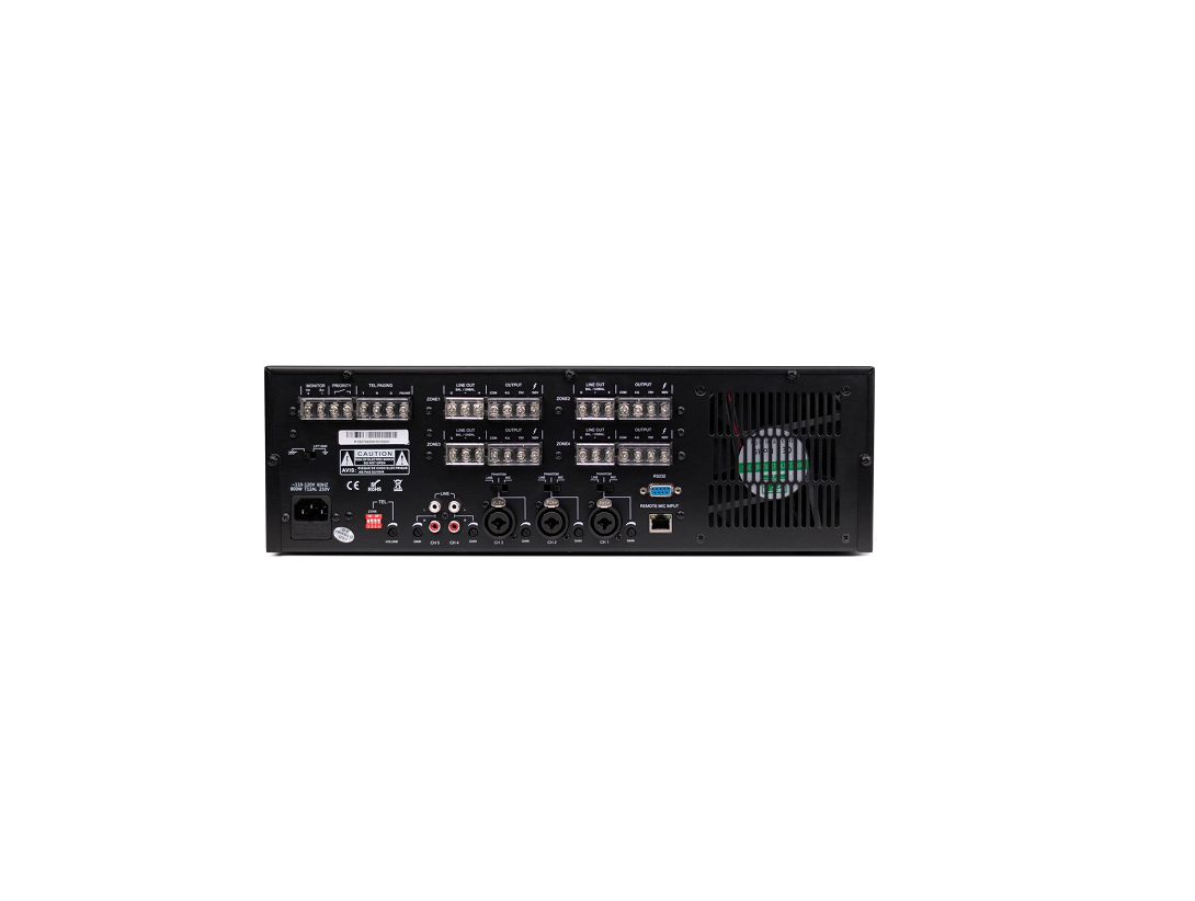
REAR PANEL
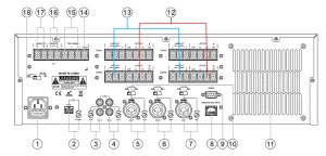
- AC power input socket
- Telephone DIP switch and volume control
- CH5 line signal input and signal gain control
- CH4 line signal input and signal gain control
- CH3 microphone signal input and signal gain control
- CH2 microphone signal input and signal gain control
- CH1 microphone signal input and signal gain control
- Remote microphone input port
- RS232 port
- LINE, PHANTOM, MIC signal input selector switch
- Vents REAR PANEL
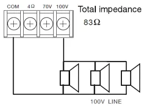
- ZONE1-4 output terminals for connecting speakers; COM is common terminal, 4Ω for 4 Ω speaker; 70V terminal for 70V use; 100V terminal for 100v
- ZONE1-4 LINE signal output
- Radio antenna port
- Telephone signal input port
- Contact PRIORITY control, can change the priority of Telephone and MIC1 inputs
- Monitor output port
- Ground lift switch
REMOTE CONTROL
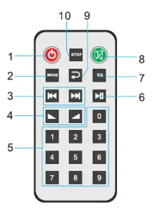
- Power switch
- Mode
- Previous/next
- Volume increase/decrease
- 0-9 number buttons
- Play/pause
- Sound effect control
- Mute
- Cycle play button
- Stop
Normal usage distance of remote control:Usually remote control use distance is 8 meters when there is no obstacle. The remote control angle: horizontal ± 3 5 degrees and vertical ± 1 5 degrees are valid.
Remote control usage attention:
- When install battery, please mind electrode.
- Please let remote control aim right with window of host machine.
- When found remote distance get short and insensitive, please change battery.
- Please take out battery when don’t use it for a long time.
- Take it easy in case of falling.
OPERATION
STARTING -UP PROCEDURE
- Set “LEVEL” volume knobs to the “0” position (counterclockwise position) on the front panel. Set “TREBLE” and “BASS” knobs set to “12 0 clock” position (straight up)
- Set Gain- knobs of “CH1 to CH5” on the rear panel to counterclockwise for minimum gain to start
- Set “TEL” dipswitches in down position on back of amp.
- Press the power button to “ON” position and indicator light will turn on. Blue means amplifier is working normally. Red means amplifier is under protection status. (Please check connections & input voltage.)
“CH1” TO “CH5” OPERATION INSTRUCTION
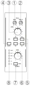
- Operational instruction is the same for “CH1” to “CH5”. Take “CH2” illustration as an example:( 1)Adjust “BASS” button: to change the low frequency of Tone quality.(2 ) Adjust “TREBLE” button: to change the high frequency of Tone quality.( 3)”MUTE” button: Push mute button to mute input source(4 ) “Z1” to “Z4” button: Use to Route input to the selected zone, as indicated by the illuminated button( 5)Adjust “Input LEVEL” button: to change the input level of sound source signal.( 6)”MON” button: press “MON” button to route Output signal to Monitor Bus. When illuminated, output is routed to Monitor.(7 ) Output status: To monitor output signal. Avoid Clip & Protect lights. Clip light indicates input signal is too strong, causing output to distort). Protect light does not output signal & indicates fault with the amplifier.
- Adjust Zone 1-4 to the desired level.
MONITOR OPERATION INSTRUCTION
- Select Output to monitor.
- Adjust monitor to desired level.
OPERATION INSTRUCTION OF REMOTE MIC
“REMOTE MIC INPUT” remote Mic interface: connect to optional Pure Resonance Audio remote On Paging Mic, select zone, chime or all call. For more information see manual for remote paging mic to configure chimes, bell, & tones. Short “Priority Terminal” with a wire to set Remote Mic. input as the highest priority).
OPERATION INSTRUCTION OF TELEPHONE INPUT
“TEL. PAGING” input: Controlled only by telephone “volume” on rear panel.
- “VOLUME” sets the input signal of telephone.
- “ZONE” dial switch: assign telephone input to each zone. Flip switch up to route telephone page to the desired zone
OPERATION INSTRUCTION OF BUILT-IN MP3 PLAYER
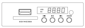
- USB and SD card have priority over Bluetooth & FM tuner.
- “MODE” button: press the “MODE”: choose radio, Bluetooth or audio playback.
- “ ” To start track over or to return to previous track.
- “ ” When playing music, press once to pause. Press again to play.
- “ ” To skip to next song.
PLEASE NOTE:
- When using the built-in MP3 player buttons, use care when pushing buttons. Avoid excessive force which can cause damage to the MP3 player button.
- When an SD card or USB interface is inserted, please insert in the correct way, avoid the wrong way or forcing it too hard causing damage to the SD card or USB interface.
SERIAL PORT APPLICATIONPlease contact or call (866) 676-7804 for more information on using serial port.
CH1, CH2, CH3 SWITCH APPLICATION
Input switch has three models: LINE, PHANTOM, MIC
- The LINE input is for line level audio source inputs, such as CD, VCD, DVD and other audio equipment.
- The PHANTOM input offers 48V power supply for a condenser microphone.
- The MIC input was used for ordinary microphones (dynamic)
MP3 MODULE RECORDING FUNCTIONFor instructions on using the MP3 module recording function please reference the recording addendum to be found at https://www.pureresonanceaudio.com.
MUTE FUNCTION
ORDER OF MUTE PRIORITYMIC1 has the highest priority in default status: Highest Priority: Mic1 > Telephone > Remote MIC. By shorting “PRIORITY” terminal, Remote MIC. has the highest priority. Highest Priority: Remote Mic > Telephone > MIC1, when “PRIORITY” when jumper is added.
SPEAKER CONNECTIONS

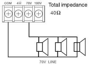
PLEASE NOTE:
- Both the 4 Ω and 70V/100V terminals cannot be used at the same time.
- Impedances indicated in the figures represent the total speaker system (load) impedances.
![]() Be sure to attach the supplied terminal cover after connection completion. Because high voltage is applied to the speaker terminals, never touch these terminals to avoid electric shock.
Be sure to attach the supplied terminal cover after connection completion. Because high voltage is applied to the speaker terminals, never touch these terminals to avoid electric shock.
TROUBLESHOOTING
| SYMPTOM | PROBLEM |
|
1. There is no sound output when the line connection is good |
1. No electricity or plug contact undesirable2. The fuse was burned out3. The volume is not open4. No input signal |
|
2. Normal startup, the alarm triggered |
1. Load short circuit or damaged2. Power supply voltage is not stable, too high or too low3. Overload |
|
3. In the normal use and all of a sudden there is no sound output |
1. Temperature is too high, the machine in temperature protection2. Loose cable connection |
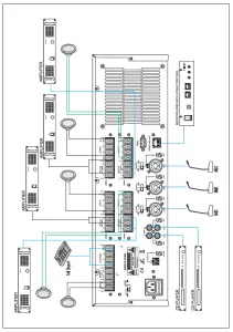
REAR PANEL CONNECTIONS
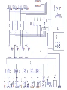
BLOCK DIAGRAM
SPECIFICATIONS
| Power Output | 4 x 120W |
| Output Interface | 4R, 70V/100V |
| Monitor Output | 1W/8 Ω |
|
Input Sensitivity and Impedance |
CH1, CH2, CH3: MIC: ± 2.5mV/600 Ω PHANTOM: ± 2.5mV LINE: ~175mV/10K Ω balance input CH5~6: 350mV/10K Ω balance input TEL: 350mV/10K Ω REMOTE MIC: ± 387mV/10K Ω |
| Tone | Bass: ±10dB at 100Hz Treble: ±10dB at 100Hz |
| SNR | >65dB |
| LINE 1-4 Output Level | 1V/600 Ω (balance output) |
| Frequency | 80-16KHz |
| MP3 | Support MP3 format, max capacity of 32GB |
| SD File System | Only FAT16, FAT32, the biggest one partition, does not support folder to store |
| Harmonic Distortion | <1% |
| Power Comsuption | 750W |
| Supply Voltage | ~120V 60Hz |
| Dimensions (H x W x D) | 5.20” (132 mm) x 19.06” (484 mm) x 17.32” (440 mm) |
| Weight | 41.2 lbs (18.69 kg) |
| Shipping Weight | 48 lbs (21.77 kg) |
REAR PANEL CONNECTIONS
UNIT: MM
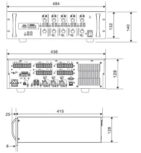
Keep all sides of the unit over 10 cm away from objects that may obstruct airflow to prevent the unit’s internal temperature from rising.
SERVICE
Ensure the problem is not related to operator error, or system devices that are external to this unit. Information provided in the troubleshooting portion of this manual may help with this process. Once it is certain that the problem is related to the product contact your warranty provider as described in the warranty section of this manual.
LIMITED WARRANTY
PRO ACOUSTICS, LLC. (“PRO ACOUSTICS”) warrants this product to the original purchaser to be free from defects in materials and workmanship (subject to the terms set forth below), for the following periods from the date of purchase.
THIS WARRANTY COVERS THE LISTED PRODUCTS AGAINST DEFECTS IN MATERIALS OR WORKMANSHIP FOR THE FOLLOWING PERIOD
Warranty Terms
Speakers 2 YearsAmplifiers & Electronics 1 YearMicrophones 1 YearAccessories 1 Year
PRO ACOUSTICS will repair or replace (at PRO ACOUSTICS’s option) this product or any defective parts (excluding electronics and amplifiers) in this product. Your authorized PRO ACOUSTICS dealer will inspect the product and, if your dealer is not equipped to perform the repair of your PRO ACOUSTICS product, they will replace your product or return it to PRO ACOUSTICS for repair, at their discretion. Proof of purchase in the form of a bill of sale or receipted invoice,which is evidence that this product is within the warranty period, must be presented to obtain warranty service.This warranty is invalid if the factory applied serial number has been altered or removed from this product.This warranty is invalid if this product was not purchased from a PRO ACOUSTICS authorized dealer. Cosmetic damage or damage due to the accident, acts of God, misuse, abuse, negligence, commercial use, or modification of, or to any part of, the product are not covered in this warranty. This warranty does not cover damage due to improper operation, maintenance or installation, or attempted repair by anyone other than PRO ACOUSTICS or a PRO ACOUSTICS dealer which is authorized to do PRO ACOUSTICS warranty work. Any unauthorized repairs will void this warranty.This warranty does not cover products sold as is.REPAIRS OR REPLACEMENTS AS PROVIDED UNDER THIS WARRANTY ARE THE EXCLUSIVE REMEDY OF THE CONSUMER/PURCHASER. PRO ACOUSTICS U.S.A. SHALL NOT BE LIABLE FOR ANY INCIDENTAL OR CONSEQUENTIAL DAMAGES FOR BREACH OF ANY EXPRESS OR IMPLIED WARRANTY ON THIS PRODUCT. EXCEPT TO THE EXTENT PROHIBITED BY LAW, THIS WARRANTY IS EXCLUSIVE AND IN LIEU OF ALL OTHER EXPRESS AND IMPLIED WARRANTIES WHATSOEVER, INCLUDING BUT NOT LIMITED TO, THE WARRANTY OF MERCHANTABILITY AND FITNESS FOR A PRACTICAL PURPOSE.
This warranty gives you specific legal rights. You may have other rights which vary from state to state.
PURE RESONANCE AUDIO®(866) 676-7804Specifications may change without notice. www.PureResonanceAudio.com
Read More About This Manual & Download PDF:
References
[xyz-ips snippet=”download-snippet”]