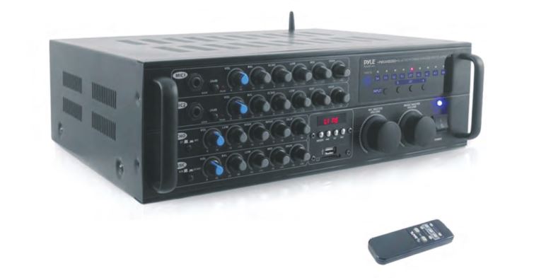
PYLE 2000 Watt Wireless BT Streaming Stereo
Mixer Karaoke Amplifier User Manual
![]()


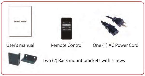
What is Included:
- User’s manual ~1
- Remote control~1
- One AC Power Cord ~ 1
- Two (2) Rack mount brackets with screws ~ 2
Safety Instructions

Explanation of Graphical Symbols
![]() The lightning flash & arrow head symbol, within an equilateral Triangle, is intended to alert you to the presence of Danger.
The lightning flash & arrow head symbol, within an equilateral Triangle, is intended to alert you to the presence of Danger.
![]() The exclamation point within an equilateral triangle is Intended to Alert you to the presence of important operating and servicing instructions.
The exclamation point within an equilateral triangle is Intended to Alert you to the presence of important operating and servicing instructions.
WARNINGTo reduce the risk of fire or electric shock, Do not expose this unit to rain or Moisture.
- Read Instructions: All the safety and Operating instructions should be read before the Appliance is operated.
- Retain Instructions: The safety and Operating instructions should be retained for future reference.
- Heed Warnings: All warnings on the appliance and in the operating instructions should be adhered to.
- Follow Instructions: All operating and use instructions should be followed.
- Attachments: Do not use attachments not recommended by the product’s manufacturer as they may cause hazards.
- Water and Moisture: Do not use this unit near water. For example, near a bathtub or in a wet basement and the like.
- Carts and Stands: The appliance should be used only with a cart or stand that is recommended by the manufacturer. 7A. An appliance and cart combination should be moved with care. Quick Stops, excessive force, and uneven surface may cause an overturn.
- Ventilation: The appliance should be situated so its location does not interfere with its proper ventilation. For Example, the appliance should not be situated on a bed, sofa, rug, or similar surface that may block the ventilation slots.
- Heat: The appliance should be situated away from heat sources such as radiators, heat registers, stoves, or other appliances (including amplifiers) that produce heat.
- Power Sources: The appliance should be connected to a power supply only of the type described in the operating instructions or as marked on the appliance.
- Grounding or Polarization: Precautions should be taken so that the grounding or polarization means of an appliance is not defeated.
- Power-Cord Protection: Power-supply cords should be routed so that are they not likely to be walked on or pinched by items placed upon or against them, paying particular attention to cords at plugs, convenience receptacles, and the point where they exit from the appliance.
- Cleaning: Unplug this unit from the wall outlet before cleaning. Do not use liquid cleaners or aerosol cleaners. Use a damp cloth for cleaning.
- Power Lines: An outdoor antenna should be located away from power lines.
- Non-Use Periods: The power cord of the appliance should be unplugged from the outlet when left unused for a long period of time.
- Object and Liquid Entry: Care should be taken so that objects do not fall and liquids are not spilled into the enclosure through openings.
- Damage Requiring Service: The appliance should be serviced by qualified service personnel when:
- A. The power supply cord or plug has been damaged.
- B. Objects have fallen into the appliance or the appliance has been exposed to rain
- C. The appliance does not appear to operate normally
- D. Exhibits a marked change in performance
- E. The appliance has been dropped, or the enclosure has been damaged.
- Servicing: The user should not attempt to service the appliance beyond that described in the operating instructions. All other servicing should be referred to qualified service personnel.
CAUTION:READ THIS BEFORE OPERATING YOUR UNIT
- To ensure the finest performance, please read this manual carefully. Keep it in a safe place for future reference.
- Install your unit in a cool, dry, clean place away from windows, heat sources, and too much vibration, dust, moisture. Avoid sources of hum (transformers, v motors). To prevent fire or electrical shock, do not expose to rain and water.
- Do not operate the unit upside-down.
- Never open the cabinet. If a foreign object drop into the set, contact your dealer.
- Place the unit in a location with adequate air circulation. DO NOT interfere with its proper ventilation; this will cause the internal temperature to rise and may result failure.
- Do not use force the switches, knobs or cords. When moving the unit, first turn OFF the unit. Then gently disconnect the power plug and the cords connecting to other equipment. Never pull the cord itself.
- Do not attempt to clean the unit with chemical solvents: this might damage the furnish. Use a clean, dry cloth.
- Be sure to read the “Troubleshooting” section on common operating errors before concluding that your unit is faulty.
- This unit consumes a fair amount of power even when the power switch is turned off. We recommend that you unplug the power cord from the wall outlet if the unit is not going to be used for a long time. This will save electricity and help prevent fire hazards. To disconnect the cord, pull it out by grasping the plug. Never pull the cord itself.
- To prevent lightning damage, pull out the power cord and remove the antenna cable during an electrical storm.
- The general digital signals may interfere with other equipment such as tuners or receivers. Move the system farther away from such equipment if interference is observed.
NOTE: Please check the copyright laws in your country before recording from records, compact discs, radio, etc. Recording of copyrighted material may infringe copyright laws.
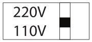
Voltage Selector (General Model Only)Be sure to position the voltage selector to match the voltage of your local power lines before installing the unit.
CAUTIONThe apparatus is not disconnected from the AC power source so long as it is connected to the wall outlet, even if the apparatus itself is turned off. To fully insure that the apparatus is indeed fully void if residual power, leave unit disconnected from the AC outlet for at least fifteen seconds.
Getting Connected
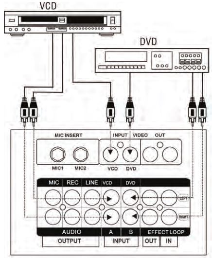
CD/DVD Player Connection
You can simultaneously connect up to two CD/DVD players to the Unit’s Switchable A/V channels, remote or front panel, you can easily switch between Channel A and Channel B.
Audio
Connect the stereo (L/R) RCA cables from the output of your CD/DVD player to the VCD (INPUT A) or the DVD (INPUT B) L/R inputs on the rear panel of the unit.
Video
Connect the video RCA cable from the Video output of your CD/DVD player to the VIDEO INPUT on the rear panel of the Unit.
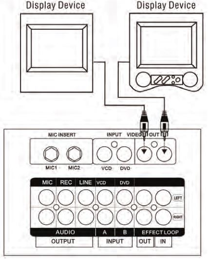
TV/Display Device Connection
The unit has two video inputs and two video outputs. Video inputs A and B correspond to the two input channels. The video that is being input into VIDEO input A will only play when input channel A is active. Likewise, the video that is being input into VIDEO input B can only be viewed if input channel B is Active. Both Video Outputs send the same picture simultaneously to two different TV’s or display devices. Connect the Video RCA cable from the VIDEO output on the unit to the Video Input on your TV or display device.
NOTE: Switch between Inputs A and B either by using the A/B buttons on the unit’s remote or on the front panel.
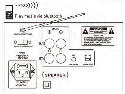
WIRELESS BT FUNCTION
- Ensure Wireless BT is turned ON in your mobile device.
- With the mixer system powered ‘ON’, search for available Wireless BT networks from your mobile device. The mixer will appear in the Bluetooth network list as ‘PYLE SPEAKER’.
- Connect and pair to ‘PYLE SPEAKER’*You may be prompted to enter a password, if so enter ‘0000’ (zeroes)
NOTES:
- Available operation range of Wireless BT function of the unit is 10 meters. Be sure there are no obstacles between the unit and your mobile phone or it will affect the Wireless BT connection which may cause broken sounds
- This operation is only available for mobiles with Wireless BT function.
- Above operation is based on NOKIA 6500s. Other mobiles may have different setting and steps to play music via Wireless BT, please have a look at Wireless BT setting in your mobiles phone’s manual.
Amplifier, Mixer and External Sound System Connections
Music and Vocals
The unit’s LINE OUT (RCA) jacks can be used to connect to a second power amplifier, an external sound system or mixing device.
Note: The unit offers optimum performance when used as an amp for home sound systems and smaller performance systems and speakers. Use L/R RCA audio cables to connect to an amplifier, mixer or other external sound system. Connect from the L/R LINE OUTPUT on the unit to the L/R audio input on your amp, mixer or sound system. Digital Karaoke Mixing Amplifier with Key Control
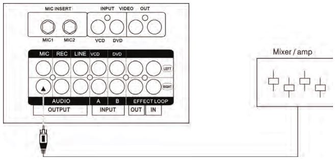
Outputting Vocals Independently
You can output vocals independently from the unit into a mixer from the L/R RCA MIC Outputs. Connect the L/R RCA cable from the MIC OUTPUT to an Audio Input on your mixer.
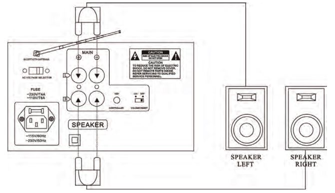
External Speaker Connection
You can directly connect to speakers using either MDP (banana plug) speaker cables or standard speaker wires. Be sure to correctly match the polarities (+/-). Connect rated speakers no lower than 4-0hms to the unit. Please do not try to connect more than one speaker per channel, as the load may exceed the amplifiers handling capacity, causing it to overload.
If using standard speaker wire, unscrew each plastic bind until you are able to see an interior hole for speaker wire (this is easier to locate when viewing from a side angle). Slide the speaker wires into the slots and tighten the plastic binds to tighten them in place. Be sure there is no insulation on the speaker wire preventing conductivity.
Mic(s) connection
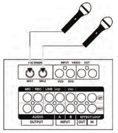
Using a mic cable with a 1/4″end, connect the mic to either of the Unit microphone inputs.
Mic with Remote Key Control
Connect the Remote Key Control cable into the KEY CONTROLLER jack on the rear panel of the unit.
Effects Loop Connections
Source Music (Music from a DVD or CD player)
By using the built-in Effects Loop you can add effects such as a professional Digital Key Controller to the source player’s music without compromising the quality of the original signal. To use the effects loop connect an RCA cable from the unit’s EFFECTS LOOP L or R OUT jack to the effects unit input. Then connect an RCA cable from the effects unit output, into the unit’s L or R IN jack.

Vocals
MIC INSERT jacks on the rear panel to loop the vocals through effects unit.

NOTE: In order to do this you must have a 1/4″ Y adapter cable (not included) for each microphone line.
Connect the single end of Y cable into the MIC INSERT jack. Connect one side of the double end into the input on the effects device and the other end into the output of the effects device.
NOTE: There will be no sound if the Y cable is plugged into the unit but the double ends are not connected to the IN and OUT of the device.
Rear Panel Description
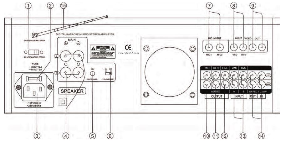
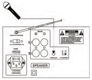
1. VOLTAGE SELECTOR Switch: This selector toggles between 110-120V and 220-240V power settings.
NOTE: Please ensure this toggle is set to the correct position, matching the receiving AC outlets power supply before plugging it IN and operating it. Doing so may cause severe damage to the unit and void your product warranty.
2. FUSE Terminal: This terminal houses the main system FUSE. NOTE: If fuse replacement is necessary, only replace with the same type and rating of fuse.
3. AC-IN Terminal: Connect AC MAINS POWER CORD from the wall outlet to this terminal.
4. SPEAKER BINDING posts (MDP): Connect appropriate speaker cables from these SPEAKER OUTPUT jacks to the INPUT jacks located on your speakers. Standard speaker wire or speaker cables equipped with MDP (banana) plugs can be used with the SPEAKER BINDING posts.
NOTE: To use standard speaker wire, unscrew the plastic color- coded (red-black) binds until you can access the wire holes located on the inner-sides of the binds and slide the wire leads into them. Fasten them down by re-tightening the binds.
5. REMOTE KEY CONTROL: This 1/8″ jack is for connecting a REMOTE KEY CONTROL cable. Remote Key Control allows you to make key changes at a distance from the Digital Key Controller on the unit.
6. VOLUME RESET switch: The master MIC and MISIC volumes on the are programmed to reset back to zero every time the machine’s power is turned off. The VOLUME RESET switch allows you to turn this feature off. When this switch is in the ON position, the volume will reset whenever the machine is turned off and when in the OFF position, the volume will stay the same when the machine is turned off.
7. MIC INSERT jacks: These 114″ jacks allow you to loop each microphone line through an effects unit.
NOTE: In order to do this you will need a 1/4″ Y cable (not included). See “Connecting to an effects system using the Effects Loop” instructions in the GETTING CONNECTED section of this manual for further instructions on running vocals through an effects loop.
8. VIDEO INPUT (RCA) jacks: Connect RCA-ended video cables from these jacks to the VIDEO OUT jacks on the device connected to your VCD (Input A) or DVD (Input B) player.
9. VIDEO OUTPUT (RCA) jacks: Connect RCA-ended video cables from these jacks to the VIDEO IN on a TV or display device. These are not independent outputs; they both output the same video signal simultaneously.
10. MIC OUTPUT jacks: These jacks output the two mic channels without any music. Connect a paired RCA-ended patch cable from these jacks to the appropriate INPUT jacks on a mixer or vocal effects unit.
NOTE: MIC OUTPUT from these jacks is dry. Echo effects will not be applied to this MIC OUTPUT, regardless of the current master and channel echo settings.
11. REC OUTPUT jacks: These jacks provide connection to recording and other external audio devices. Connect a paired RCA ended patch cable from these jacks to appropriate INPUT jacks on the recording or other audio/video device.
12. LINE OUTPUT jacks: These jacks output both mic channels and source music together.
13. AUDIO INPUT jacks: Input audio from a VCD or DVD player into either of these channels. The audio from channel A can only be heard when channel A is selected on the input selector and the audio from channel B can only be heard when channel B is selected on the input selector.
14. EFFECTS LOOP jacks: Use the EFFECTS LOOP jacks to connect an external effects unit, such as a key controller or EQ. After removing the LOOP-BARS, connect a patch cable from the OUTPUT jacks of your external effects unit to the EFFECT LOOP IN jacks. Connect a second patch cable from the INPUT jacks of your external effects unit to the EFFECT LOOP OUT jacks
NOTE: Do not discard the loop-bars. It is necessary for the loop-bars to be in place when there is no external effects unit being used.
15. WIRELESS BT ANTENNA: Pease pull the antenna out when using Wireless BT input
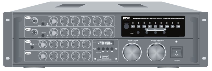
Front Panel Description
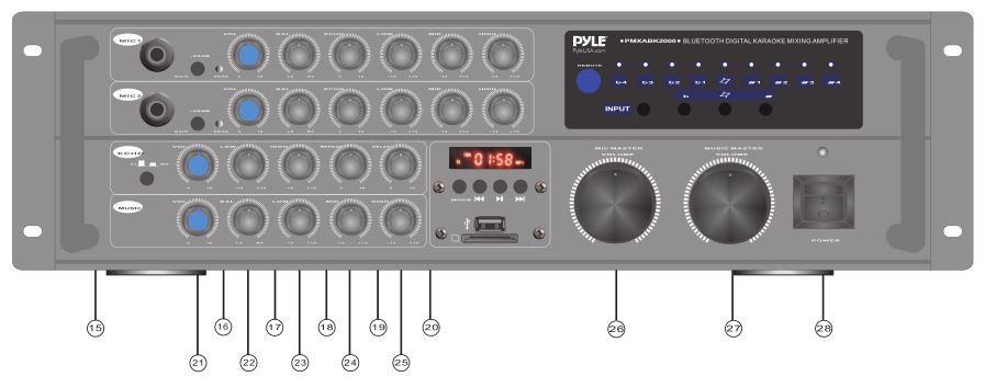
15. ST/MO (Stereo/Mono): Use this button to switch between the two echo output modes, STEREO and MONO.
16. MASTER ECHO VOLUME control: This control increases/decreases the MASTER VOLUME LEVEL of the ECHO effect available to the MIC 1-2-3 channels. Turn clockwise to increase MASTER ECHO VOLUME and counter-clockwise to decrease the MASTER ECHO VOLUME.
17. ECHO LO. control: This control increases/decreases the amount of LOW frequency response applied during the ECHO effect application. Turn clockwise to increase the LOW frequency response, and counter -clockwise to decrease the LOW frequency response.
18. ECHO HI. control: This control increases/decreases the amount of HIGH frequency response applied during the ECHO effect application. Turn clockwise to increase the HIGH frequency response, and counter-clockwise to decrease the HIGH frequency response.
19. ECHO RPT. control: REPEAT adjusts the interval repetition of the echo effect. As more REPEAT is applied to the ECHO effect, more echo intervals will occur prior to fading out. Turn clockwise to increase the REPEAT level and counter-clockwise to decrease the REPEAT level.
20. ECHO DEL. control: DELAY adjusts the total beginning and ending length of each echo interval. As more DELAY is applied to the ECHO effect, each ECHO interval will become longer in time. Turn clockwise to increase the DELAY level and counter-clock wise to decrease the DELAY level.
21. MUSIC VOL. control: This control increases/decreases the MUSIC VOLUME level(s) from INPUT SOURCES that are connected to the CD/DVD channels. Turn clockwise to increase MUSIC VOLUME and counter -clockwise to decrease the MUSIC VOLUME.
22. MUSIC BALANCE control: Use this control to fade the music output between the left and right channels. When the balance control is directly centered, equal sound comes out of both the left and right channels giving you perfect stereo sound.
23. MUSIC LOW. control: This control increases/decreases the amount of LOW (bass) frequency response applied to the audio output of INPUT SOURCES connected to the CD/DVD channels. Turn clockwise to increase the LOW frequency response and counter- clockwise to decrease the LOW frequency response.
24. MUSIC MID. control: This control increases/decreases the amount of MID-RANGE frequency response applied to the audio output of INPUT SOURCES connected to the CD/DVD channels. Turn clockwise to increase the MID-RANGE frequency response and counter-clockwise to decrease the MID-RANGE frequency response.
25. MUSIC HIGH control: This control increases/decreases the amount of HIGH frequency response applied to the audio output of INPUT SOURCES connected to the CD/DVD channels. Turn clockwise to increase the HIGH frequency response and counter-clockwise to decrease the HIGH frequency response.
26. MIC MASTER VOLUME control: Use this to control the overall volume of both microphone channels. Turn clockwise to increase the master microphone volume and counter-clockwise to decrease the master microphone volume.
27. MUSIC MASTER VOLUME control: Use this to control the overall volume of the music from the CD/DVD player that is input into the unit..
28. POWER button: This button turns the unit ON and OFF.
Remote Control Description
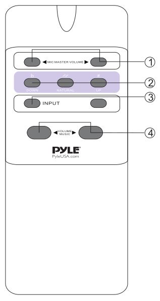
1. MIC MASTER VOLUME control: Use this to control the overall volume of both microphone channels. Turn clockwise to increase the master microphone volume and counter-clockwise to decrease the master microphone volume.
2. DIGITAL KEY CONTROL: Use these buttons to raise or lower the musical key of your source music (CD/DVD player). The LEDs indicate where the current key of the music is.b – Lowers the key of the music◊ – Restores the music back to its original (natural) key# – Raises the key of the music
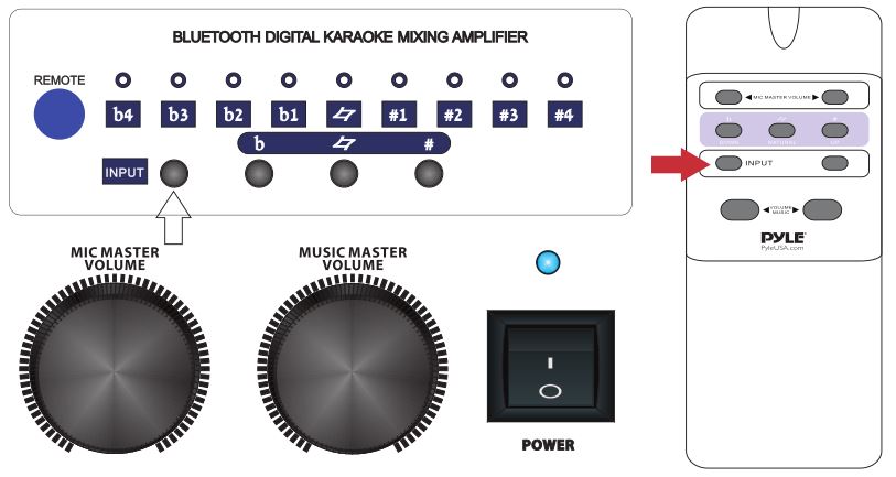
3. INPUT SELECTOR buttons: Use these buttons to toggle between the three available input channels DVD,VCD and MP3/bluetooth
4. MUSIC MASTER VOLUME control: Use this to control the overall volume of the music from the CD/DVD player that is input into the unit.
Switching between input channels
Use the (DVD, VCD, MP3) input button’s on the units front panel or remote control to switch between the three input channels.
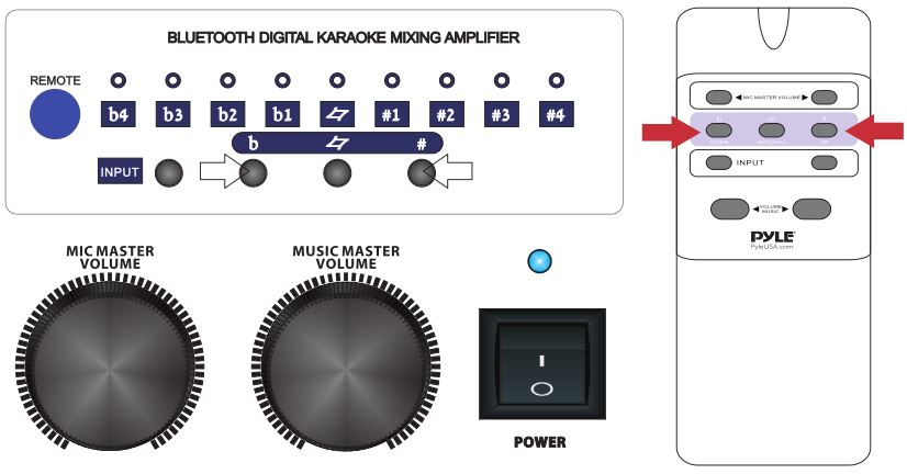
Using Digital Key Control
Digital Key Control enables you to adjust the key of the source music (CD/DVD player) to fit the vocal range of the person who is singing. The key can be adjusted by using the key control buttons on the unit’s front panel, the remote control or from a Remote Key Control microphone.b – Lowers the key of the music◊ – Resets the key back to its original (natural) state# – Raises the key of the music
Advanced Operations
Balancing the Music with the Vocals
The unit has MASTER, HIGH, MID and LOW controls for both the music and the microphone levels, which enables you to adjust your mix levels with precision, resulting in a professional-sounding mix. If you find that the music is too loud, simply adjust the MUSIC VOLUME control. Also, keep in mind that HIGH, MID and LOW levels also affect the overall “sound” and can be adjusted to correct sound balancing problems. Excessive high (treble) frequencies can lead to feedback, so be careful when adjusting them.
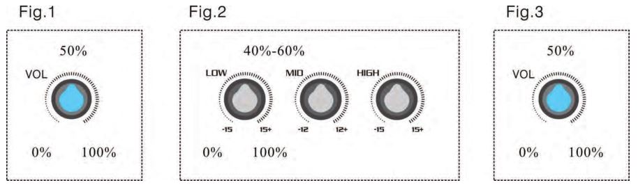
Balancing a Microphone Channel
When adjusting Mic levels, it is recommended to do so in this order:
- First adjust the MIC VOLUME control to approximately 50%. (Shown on Fig. 1)
- Then balance the LOW, MID and HIGH controls to approximately 40-60%. (Shown on Fig. 2)
- Start background music with the MUSIC VOLUME set at approximately 50%. (Shown on Fig. 3)
- Fine-tune each MIC CHANNEL as necessary till you get a clean balanced mix
- Remember to compensate if the background music has striking volume changes. To do this, you can utilize the -20dB GAIN PAD. The -20dB Gain Pad toggles between a current volume level and reduced gain volume level. This control can be used to immedi ately go from one volume level to another by a quick push of the button.
- Once all the settings are complete, do a complete song for complete balancing success.
Balancing the Music Channel
When adjusting the music levels follow the same procedure as seen above for Mic levels.
TROUBLESHOOTING

PMXAKB2000
2000 Watt Wireless BT Streaming Stereo Mixer Karaoke AmplifierMicrophone/RCA Audio/Video Inputs, Mic-Talkover, USB/SD Readers, Rack Mountable Amp
System Features:
- Karaoke / PA Stereo Amplifier
- Easy Audio Mixing: Mix (2) Mics with Wireless BT / RCA Input Audio
- Connects to Home Theater and External Speaker Systems
- Wireless BT Music Streaming Ability
- Microphone Talk-Over Function
- Dual Channel (A/B) Digital Amp Design
- Digital LCD Display
- USB Flash and SD Memory Card Readers
- (2) 1/4” Microphone Inputs – Front Panel
- (2) 1/4” Microphone Inputs – Back Panel
- (2) Pair (L/R) Speaker Terminal / Bind Post Connectors
- (3) Pair RCA (L/R) Audio Output Connector Jacks
- (2) Pair RCA (L/R) Audio Input Connector Jacks
- RCA Video Connector Input / Output Connectors
- Ability to Connect to Video Display, TV or Monitor
- Effects Loop (L/R) RCA Connectors
- Compatible with Outboard Effects Processors
- Input Selector and Digital Key Controls
- Front Panel Rotary Control Center
- Independent Mic Audio Configuration Controls
- Audio Master Volume and Mic Master Volume Control
- Mic Echo/Low/High/Repeat/Delay Control
- Music Low/Mid/High/Balance Control
- Built-in Ventilation Cooling Fan
- Rack Mountable System
Wireless BT Streaming Connectivity:
- Instantly Receives Wireless Music Streaming
- Works with all of Your Favorite Devices (iPhone, Android, Smartphone, iPad, Tablet, etc.)
- Wireless BT Version: 3.0
What’s in the Box:
- Rack Mount Brackets
- RCA Audio Connection Cable
- Remote Control · Power Cable
Technical Specs:
- MAX Power Output: 2000 Watt
- 1000 + 1000 @ 4 Ohm
- 750 + 750 @ 8 Ohm
- Bluetooth Version: 2.0
- S/N Ratio: 65dB
- T.H.D.: 0.5%
- Frequency Response: 20Hz – 20kHz
- Noise Level: <10mV
- Tone Balance Control: +/-12dB
- Balance Input: +/-1.5dB
- Split Level: >35dB
- Mic Sensitivity: <30mV
- Mic Frequency: 100-2.5kHz
- Digital Audio File Compatibility: MP3/WMA
- Maximum USB/SD Card Support: 8GB
- Power: 110/220V, Switchable
- Dimensions (L x W x H) 13.5” x 16.5” x 5.5”
- Sold as: 1
- Weight: 17.26 lbs.
![]()
Visit us OnlineHave a questions ?Need a service or repair ?pyleusa.com/contactus
Questions? Issues?We are here to help!Phone: (1) 718-535-1800Email: [email protected]
References
[xyz-ips snippet=”download-snippet”]