![]()
![]()
![]()
PLMRA402Elite Series Waterproof Amplifier400 Watt 4-Channel Amp System,Dual MOSFET Power Supply
![]()
Read through this user manual before using the product to ensure its correct use. Keep this manual for future reference.
INTRODUCTION
The PLMRA402 has been designed using the latest electronic technology available.The PLMRA402 is with engineered features allowing you to produce high-quality stereo reproduction in mobile applications. This innovative system has been designed with a 12 volts DC negative ground power supply.Easy installation with mounting hardware is provided. The PLMRA402 has two input levels. The high or low impedance input can be connected to units that incorporate BTL circuity or common-ground types.
![]()
FUNCTIONS
- POWER ON LED: Lights up when the remote on the system is energized.
- INPUT GAIN CONTROL: Adjust high impedance input gain from 1 V to 300mV for best matching with PREAMP output for your car stereo.
- LOW IMPEDANCE INPUT (HIGH-LEVEL INPUT): This unit is provided with two terminal inputs (Front & Rear) for LOW impedance. If your car stereo has four speaker outputs (LF, RF, LR, RR). Wire input as per FIG. 3 & FIG 3A.If your car stereo has two speaker outputs, please wire as per FIG 4 & FIG 4A.
- HIGH IMPEDANCE INPUT (LOW-LEVEL INPUT): This unit is provided with gold plated RCA input jacks for high impedance. Couple the RCA input with the car stereo output using RCA-type connector cables. If your stereo has only left and right 2 channels outputs. You must use a Y-adaptor for connection (FIG 2).
- POWER FUSE: The power fuse protects both this amplifier and the automobile electrical system from wrong electrical conditions.
- POWER SUPPLY TERMINAL: Connect the +12V DC power supply wire into this terminal. By lugs and screws accessible at the panel of this amplifier (Fig. 5).A. BATT +: Connect +12V DC power supply wire into this terminal from the (+)terminal of the battery.B. GROUND: The ground terminal connects the ground wire from the chassis of the automobile.C. REMOTE: Remote terminal connects the control wire which provides remote turn-on and off of the amplifier by the RADIO/CASSETTE players power antenna wire.
- SPEAKERS TERMINALS: Speakers can be easily connected to signal barrier strips. You may use 4 to 8 ohms speakers. Before connecting, please check speaker connection diagrams.
ELECTRICAL AND AUDIO CONNECTIONS
A. STEREO INPUT CONNECTION
- High impedance input

- Low impedance (BTL or Common Ground) Inputa. Four Speaker Output Modea-1. Floating Ground Type
![]()
a-2. Common Ground Type![]()
b. Two Speaker Output Modeb-1. Floating Ground Type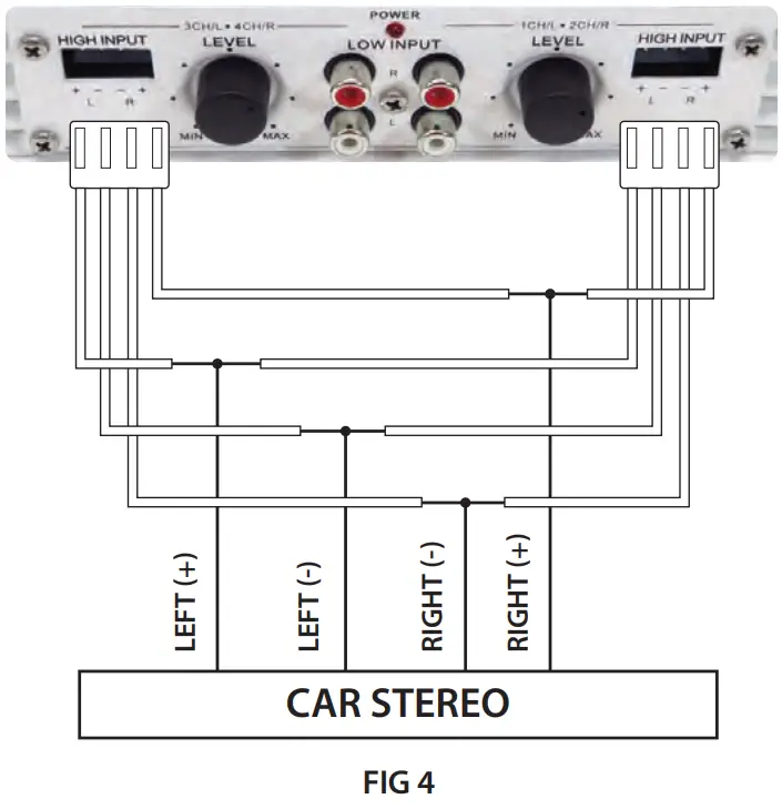
b-2. Common Ground Type

NOTE: High and low impedance input cannot be used at the same time.B. SPEAKER CONNECTIONConnect the speaker output terminals to the corresponding speakers. (Figure 5)The speakers must be high quality and capable of handling high power.Separated return paths and strong wires are required. (Fig. 5)NOTE:This amplifier has built-in short circuit protection. If you mistakingly connect any speaker wires to the ground, or positive power (+) and (-) wires short together, the protection circuit will operate automatically and cut-off output. In case of this, you must switch OFF the whole system immediately double-check speaker wire connections and isolation before switching on the amplifier again.
C. POWER CONNECTION
- Connect the B+12V pole of the power supply directly to the battery (+) position terminal.
- Connect the GND pole of the power supply directly to the (-) negative ground battery terminal or car chassis.
- To make a good grounding and prevent motor boating noise problems connect another 12 gauge minimum wire from the (-) negative battery terminal to the chassis of the stereo unit.
- Connect the ‘Remote’ pole to the external switch for positive 12V ON/OFF.This may be connected to the receiver power antenna lead.
INSTALLATION
This amplifier comes complete with mounting hardware, if the unit is used in the line-level (high impedance) mode, it is recommended to use gold plated RCA connection cables with the length as short as possible and mount the unit as close as possible to the receiver. This will lower the chance of stray magnetic pick up that may cause noise in the system.
- Choose a suitable location.
- Check the clearance behind and above the mounting area.
- Wire unit according to the proper wiring diagram.
- Using the hardware provided, attach the unit to the mounting surface.
MAINTENANCE
Your PYLE power Amplifier is an example of superior design and craftsmanship.The following suggestions will help you care for your amplifier so you can enjoy it for years.
 |
Keep the amplifier dry. If it gets wet, wipe it dry immediately.Liquids can contain minerals that corrode electronic circuits. |
 |
Use and store the amplifier only in normal temperature environments.Temperature extremes can shorten the life of electronic devices and distort or melt plastic parts. |
|
Handle the amplifier gently and carefully. Dropping it can damage circuit boards and cases and can cause the amplifier to work improperly. |
|
Keep the amplifier away from dust and dirt which can cause premature wear of parts. |
 |
Wipe the amplifier with a damp cloth occasionally to keep it looking new.Do not use harsh chemicals, cleaning solvents, or strong detergents to clean the amplifier. |
TESTING
- After all the connections have been made, turn ON your stereo and listen for the amplifier to turn ON. If there are any unusual noises from the speakers then turn the system off and recheck all the wiring.
- After you have connected your radio or equalizer to the amplifier, you may adjust the gain control to match the output level of your radio.A. Set the volume control on your radio to 2/3 position.B. Adjust the gain control for an average listening level.C. Turn the radio volume all the way down and listen for background noise.D. Start your vehicle and listen for electrical noise.E. Making fine adjustments to the sensitivity can reduce background noise and some engine noise.F. CAUTION: Never turn the sensitivity up any farther than you need to get clear sound at 2/3 volume.G. This adjustment only needs to be made once.
California Prop 65 Warning
![]() WARNING:This product contains Nickel carbonate which is known to the state of California to cause cancer birth defects and other reproductive harm. Do not ingest.For more info go to: www.P65warnings.ca.gov
WARNING:This product contains Nickel carbonate which is known to the state of California to cause cancer birth defects and other reproductive harm. Do not ingest.For more info go to: www.P65warnings.ca.gov
Features:
- 4-Channel Amp System
- Dual MOSFET Power Supply
- Marine Grade Construction
- Waterproof Marine Rating IP-01
- Dual Adjustable Input GAIN Level Controls
- Dual High-Level Speaker Input Connectors
- Dual RCA (L/R) Input Connector Jacks
- Gold-Plated Speaker Output Terminal Connectors
- Adjustable Input GAIN Level Control
- Anti-Thump Delay Circuitry
- Built-in Thermal, Overload & Speaker Short Protection
- Heavy-Duty Aluminum Alloy Heatsink
- Power ON LED Indicator
- Remote Turn ON/OFF
What’s in the Box:
- 4-Ch. Marine Amplifier
- Audio Connection Cables
Technical Specs:
- Output Power: 100 Watt x 4 MAX
- Amplifier Class: AB
- Fuse Type: 20A
- Input Gain Impedance Adjustment: 1 – 300mV
- Frequency Response: 15 – 30kHz +/-3dB
- Input Impedance: 10k Ohms (Low), 100 Ohm (High)
- Input Sensitivity: 250mV (Low), 2.5V (High)
- T.H.D.: <0.04%
- Matching Speaker Impedance: 4-8 Ohms
- Power Supply: DC 12V
- Dimensions (L x W x H): 9.0” x 7.9” x 2.0” -inches
 report this ad
|
VISIT US ONLINE:Have a question?Need service or repair?Want to leave a comment?PyIeUSA.com/ContactUs |
Questions? Issues?We are here to help!Phone: (1) 718-535-1800Email: [email protected]www.PyleUSA.com
References
[xyz-ips snippet=”download-snippet”]