IQ Panel 2/2+ Software Version 2.6.0
INSTALLATION MANUAL
Qolsys IQ Panel 2/2+ Software Version 2.6.0
The Qolsys IQ Panel 2 & IQ Panel 2+ is a 7″ touchscreen built with an Android operating system, providing full security and smart home functionality in an easy to use interface.
INTRODUCTION
INCLUDED IN BOXIQ Panel 2/2+
Power Supply
Table Stand
ABOUT THIS GUIDEThis document outlines the basic hardware specifications and software directions to install and customize the IQ Panel 2 & IQ Panel 2+. Note that the information presented is not comprehensive, but is specifically dedicated to those menus, features, and systems accessible solely to those with the proper installation code. Features accessible to users and installers alike are outlined in the IQ Panel 2 User Guide. The information contained is confidential and proprietary, and is solely owned by Qolsys Inc. Any reproduction, modification or distribution without permission is strictly prohibited.QOLSYS CONFIDENTIAL AND PROPRIETARY PAGE 2 OF 183
SUPPORT?QUESTIONS?Contact us at
TABLE OF CONTENTS
PANEL OVERVIEW 5- Exterior Front 6- Exterior Back 7- Interior INSTALLING THE PANEL 9- Wall Mount Option 10- Table Stand Option 11- Wiring Diagram 12- Powering the Panel USER INTERFACE 14- Home Screen Overview 15- Message Center 16- Settings Tray PROGRAMMING 18- Screen Lock 19- Settings 21- Advanced Settings 22- Setup Wizard 26- Installation 28- Installer/Dealer Settings 37- System Logs 38- Siren and Alarms 41- Security and Arming 44- Camera Settings 46- Z-Wave Device List 47- Sound 51- Partitions 52- Local Automation SECURITY SENSORS 55- Security Sensors
56- Auto Learn Sensor 57- Add Sensor 58- Scan QR Code 59- Partition Name 60- Sensor Type 61- Sensor Groups 77- Sensor Name 79- Chime Type 80- Voice Prompts 81- Source 82- Edit Sensor 83- Delete Sensor 84- Sensor Status 86- Panel Motion Settings WI-FI DEVICES 88- Wi-Fi Devices 90- Access Point Settings 91- AP Connected Devices 92- IQ Remote Devices 93- 3rd Party Connections Z-WAVETM DEVICES 95- Z-Wave Devices 96- Add Device 97- Clear Device 98- Delete Failed Device 99- Remove All Devices 100- View/Edit Associations 101- Z-Wave Settings 103- SmartStart 104- Provisioning List
BLUETOOTH DEVICES 106- Bluetooth Devices 107- Add Device 108- Edit Device 109- Delete Device 110- Remove All Devices 111- Settings 112- Add Speaker SYSTEM TESTS 114- System Tests 116- Wi-Fi Test 117- Sensor Test 121- Cellular Test 122- Image Sensor Config 123- Z-Wave Test 124- Rediscover Network 125- Neighbor Info 126- Counters 128- Z-Wave Diagnostics 129- Advanced Z-Wave Diag 130- PowerG Test 131- Zigbee Test 132- Panel Glass Break Test 135- Dual Path Test 136- Daughter Cards Test 137- Panel Test CUSTOMIZATION 139- User Management 140- Dealer Branding 141- Contact Info 142- Load Custom Logo 143- On-Screen Billboard
144- Load Help Videos 145- Connecting to Wi-Fi 146- Weather 147- Photo Frame 150- Load Images from SD Card MAINTENANCE 152- Upgrade Software 153- Upgrade Software Using Wi-Fi 154- Software Update Via SD Card 155- Automatic Background Check 156- Battery Replacement TROUBLESHOOTING 158- About 161- Power Down 162- Panel Reboot 163- Hard Reboot 164- Panel Test Troubleshooting 166- Cannot Load Help Videos LEGAL 168- Important Information SPECIFICATIONS 177- Specifications 179- Supported S-Line Sensors 180- Supported PowerG Sensors 181- Supported 433 DSC Sensors 182- Supported 433 AT&T Sensors
PANELOVERVIEWWarning: This Product should be installed in accordance with the National Fire Alarm Code, ANSI/NFPA 72, (National Fire Protection Association, Batterymarch Park,Quincy, MA 02269) and with National Electric Code, ANSI/NFPA 70. Printed information describing proper installation, operation, testing, maintenance, evacuation planning, and repair service is to be provided with this Product. In Canada the product shall be installed in accordance with the Standard for the Installation of Residential Fire Warning Systems, CAN/ULC-S540.Warning: For Canadian installations this Product and all sensors associated with it (collectively, the “System”) should be tested once a week. The test shall be performed also with primary DC power de-energized. For recommended smoke detectors maintenance instructions refer to user manual associated with compatible Qolsys model QS5110-P840 smoke detector.
PANEL OVERVIEWEXTERIOR FRONTUser Interface
Panel Camera
Page Indicator
MicrophonesQOLSYS CONFIDENTIAL AND PROPRIETARY PAGE 5 OF 183
LED Status Light
PANEL OVERVIEW
EXTERIOR BACK
Mounting holes single, double or triple “gang” boxcompatible
Micro SD Card SlotSpeakerRF Antenna routing holeFor UL1610 applications this screw shall be used for tamper protection against mounting removal
Microphone
Rear Access Cover
Optional locking screw for wall mount
QOLSYS CONFIDENTIAL AND PROPRIETARY PAGE 6 OF 183
Optional locking screws for tablemount SirenSpeaker Microphone
PANEL OVERVIEW
INTERIOR
PowerG or Image Sensor Radio(PowerG Radio is Standard on IQ Panel 2+. PowerG modem is required for UL1610 compliant installationsImage Sensor Radio is Optional and not available for use on IQ Panel 2+with PowerG)Z-Wave PlusTM RadioLTE Sim CardSecurity RF Radio(319.5 MHz, 345 MHz or 433 MHz)Tamper Switch
Cellular Antenna
Expansion Slot
PowerG or Image Sensor AntennaSiren Barrel JackPower“Tool-less” Terminal BlockPanel Battery*
*CAUTION The battery should NEVER be disconnected without following proper power-down procedures Failure to comply may result in data corruption, panel failure, and a void of the manufacturer’s warranty
QOLSYS CONFIDENTIAL AND PROPRIETARY PAGE 7 OF 183
INSTALLING THE PANEL
INSTALLING THE PANEL
WALL MOUNT OPTION
2
1
32
Note: For UL/ULC Commercial Burg installations (UL1610/ULCS304 Security Level II compliant) use only wall mount option
2
This product when installed as per these instructions does not present the risk of
fire, electric shock, or injury to persons.
11. Insert your thumb or finger under the opening onthe back cover and firmly pull up to remove. This cover is not needed for wallmount.2. Press tabs on the bottom of the panel and pull apart to remove the back plate.Mount to the wall using appropriate hardwareensuring it is level.
1. Hang the front of the panel with the hanging strap on the back plate as shown above.2. Using the provided hole in the lower right hand side of thebackplate as a template, drill a 1/4″ hole in the wall and feed the white RF antenna into the wall.3. Screw required in break-away wall tamper for UL 1610IMPORTANT: Not properlyrouting the RF antenna in thewall will greatly reduce RF sensorrange.
1Connect the power supply to the barrel jack or to the (+/Red) and (-/Black) terminals if using a custom length wire.1. Latch the bottom of the panel into place, ensuring thethe RF antenna and power wire are routed into the walland not pinched.2. Swing the panel up towards the 4 snap tabs at the top.
Firmly pinch “diagonally and down” from the top front of the bezel at all 4 snap tab locations to ensure proper closure. You will hear a “pop” or “snap” sound when each tab has closed properly and the gap along the top shouldbe tightly seated.IMPORTANT: Not properly closing the panel could result in damage to the backplateor false panel tampers.
INSTALLING THE PANELTABLE STAND OPTION
1
3
2
Insert your thumb or finger under the opening on the back cover and firmly pullup to remove.
1. With the included power supply and cable, plug the barrel connector into the jack next to the terminals asshown above.2. Route the cable under the hook next to the battery.3. Route the cable through the strain relief opening.
Replace the cover by inserting the top first, thenwhile making sure the cable passes under the opening firmly press down on the bottom until the cover “snaps” into place.
Insert table stand dowels into the 2 upper keyholes.Slide the stand firmly upwards until you hear a“click” from each side.
QOLSYS CONFIDENTIAL AND PROPRIETARY PAGE 10 OF 183
INSTALLING THE PANEL
WIRING DIAGRAMBARREL JACK FOR USE WITH SUPPLIED BARREL CONNECTOR CABLE ONLY. STRIPED WIRE IS POSITIVE (+)5vDC to 7vDC** IN BARREL JACK5vDC to 7vDC* IN GNDSENSOR 1 GNDSENSOR 2 GNDEXT SIREN GND
**WARNING! Use 5vDC to 7vDC** Power Supply ONLYInput rating: 100-240vAC, 50/60Hz, 0.2A Output rating: 5.0 – 7.0vDC, 1.0A Model SW-055100A or SW-050100A or SW-070100AB
4.7k EOL4.7k EOL+
CLOSED LOOP CIRCUIT
EXT SIREN: Maximum Voltage: 12vDC Maximum Current: 300mA
QOLSYS CONFIDENTIAL AND PROPRIETARY PAGE 11 OF 183
NOTESIMPORTANT IF USING CUSTOM LENGTH WIRE: – 5.5vDC Transformer: Use 18AWG wire no longer than 25ft to ensure sufficient power is received at the panel. – 7vDC Transformer: Use 18AWG wire no longer than 100ft to ensure sufficient power is received at the panel. * The minimum permissible wire size shall not be smaller than 22 AWG ** A 7vDC power supply is only supported on panels with hardware revision E or newer.NOTE: Inputs are used only for residential Burglary applications. SENSOR 1, 2 & EXT SIREN are not permissible in UL1610 installations.NOTE: Use only UL/ cUL listed external siren in UL/cUL listed installations. Rating:12vDC/300mA
INSTALLING THE PANELPOWERING THE PANEL
Connect power supply. WARNING! Use a 5vDC to 7vDC Power Supply ONLYIf using the provided cable, the “striped” wire is (+) Note: Power supply shall be located within same room as control unit
Press and hold the power button on the right side of the panel for 3 seconds to power up.
QOLSYS CONFIDENTIAL AND PROPRIETARY PAGE 12 OF 183
USER INTERFACE
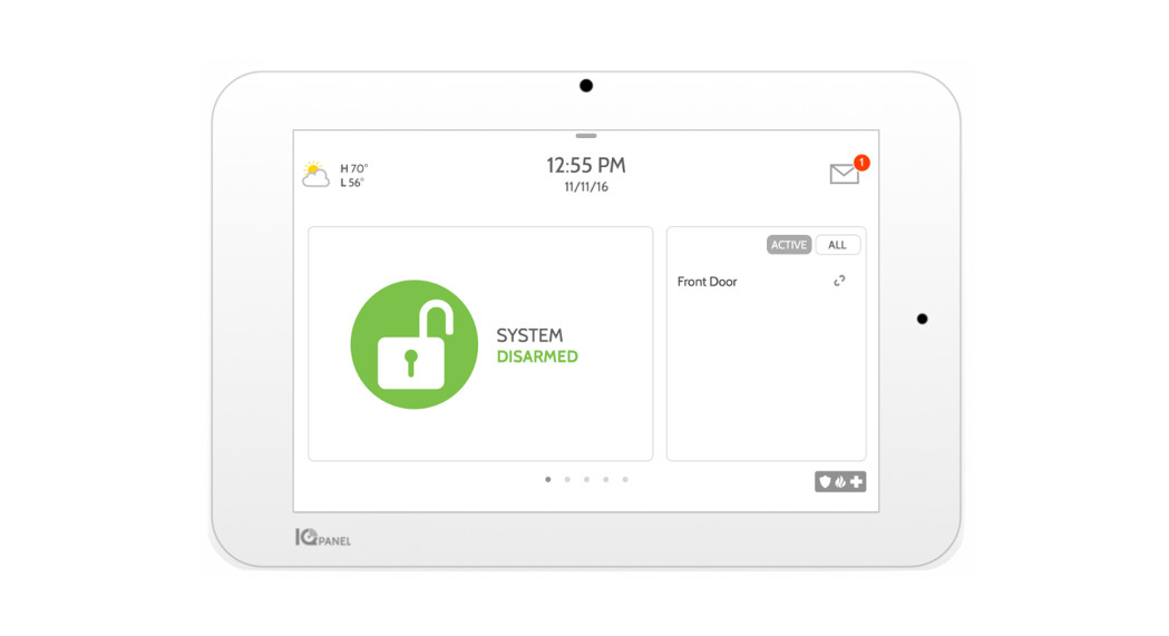
USER INTERFACEHOME SCREEN OVERVIEWThe home screen is divided into three sections. The header shows the date & time, today’s weather, message center and the Settings tray. The Primary interface shows arming options and sensor status & partition select. The footer shows panic options and additional pages.Header & Settings Tray
Primary User Interface & PartitionPage Indication andEmergency
QOLSYS CONFIDENTIAL AND PROPRIETARY PAGE 14 OF 183
USER INTERFACEMESSAGE CENTERThe header contains the the pull down settings tray, the weather icon, time/date and a message icon in the upper right portion of the screen where you will find Security Provider messages and contact info, alerts, video tutorials and FAQ’sThis is where you will find the Security Provider’s Contact Information This is where you will find Video Tutorials to help with common questions This is where you will find Panel Alerts/Alarms notifications This is where you will find messages from the Security ProviderQOLSYS CONFIDENTIAL AND PROPRIETARY PAGE 15 OF 183
USER INTERFACESETTINGS TRAYTo access the Settings tray swipe down on the bar at the top of the screen. The Settings tray has quick access to system, battery, Wi-Fi, bluetooth & cellular status as well as volume control, brightness, a lock screen icon and other quick settings.QOLSYS CONFIDENTIAL AND PROPRIETARY PAGE 16 OF 183
FIND ITSwipe down for accessWhen partitions or screen lock are ENABLED, a Lock Screen icon replaces the Status icon. Touch this icon to switch between partitions.When partitions are DISABLED, a Status icon resides in the upper left corner of the settings tray. Touch this icon to return to the security page.
PROGRAMMING
PROGRAMMINGSCREEN LOCKWhen the “Screen Lock” or “Partitions” setting are enabled, a lock screen will be presented once the panel has been woken from either a touch on the screen or pressing the wake/sleep button on the side of the panel. This prevents unauthorized access to the panel and/or one partition from accessing another as well as managing permissions to “Advanced Settings”.
4 DIGIT SCREEN LOCK
6 DIGIT SCREEN LOCK
QOLSYS CONFIDENTIAL AND PROPRIETARY PAGE 18 OF 183
PROGRAMMING
SETTINGS
The Settings page allows quick access to various simple features & settings that do not require the protection of a Dealer, Installer or Master code to be changed.
FIND ITSwipe down for access
Setting Display SD Card Weather Temperature StatusZ-WaveTM Device Status Other Z-Wave Devices
DescriptionAdjust brightness, font size & 12/24 hour timeMount, unmount and manage SD Cards that are installed in a panelToggle between Farenheight and CelciusView the “Current Status” of security sensors: Zone #, Name, Status (Open, Close, Active, Idle, Tamper, Failure), Battery and sensor History. Also view “Alarms” and “History” for security sensors globallyView the “Current Status” of Z-Wave devices: Name, Type, Status (Normal, Failure), and Battery. Also view “Alerts” and “History” for Z-Wave globallyShows Z-Wave devices that are learned into the panel but that are not part of the main user interface (Lights, Locks, Thermostats & Garage Doors)
SETTINGS
PROGRAMMING
SETTINGS
EU Events
Setting
Automation
Activity MonitorLicense Advanced Settings Smart Energy Optimizer
DescriptionDisplay events as required for EN Grade 2. NOTE: This icon will only appear when the “En Grade 2” setting is Enabled.Add, Edit or mange local lighting automation rules. These rules are separate from any cloud based rules that may be set through Alarm.com. Examples of possible rules are as follows:– Night: Turns light on at 7pm and off at 6am – Evening: Turns light on at 7pm and off at 11pm – Front Door: Turns light on for 15mins when Front Door opens between 5pm and 7am (must have asensor with the default quick name “Front Door” added in the panel) – Doorbell: Turns light on between 5pm and 7am for 15 mins when Doorbell is activated (must have asensor with the default quick name “Doorbell” added in the panel)Activity Monitor allows access to disarm sensors that are programmed as 24 hours zones, such as Sensor Groups 8, 9 & 25. A valid Master, User or Guest code is required to control 24 hour activity sensors. 2 options are provided:– Quick Access: 300 second temporary access – Deactivate: Disarms 24 hour sensors until they are re-activated manuallyQolsys End User License AgreementAccess advanced settings & programming. A valid Dealer (default 2222), Installer (default 1111) or Master Code (default 1234) is requiredShift energy usage to off-peak hours (thermostats) and reduce energy usage during on-peak hours
PROGRAMMING
ADVANCED SETTINGS
FIND IT
To access the Advanced Settings menu pull down the Settings tray at the top of the screen, select “Settings” and then “Advanced Settings”. Enter your dealer, installer or master code. The code used to enter Advanced Settings determines the level of access. When using partitions the code entered at the screen lock determines the access level for Advanced Settings.
INSTALLER MENU (1111)
DEALER MENU (2222)
Swipe down for accessSETTINGS ADVANCED SETTINGS ENTER CODE (1111, 2222)
QOLSYS CONFIDENTIAL AND PROPRIETARY PAGE 21 OF 183
* The “Partitions” icon will only appear if Partitions are enabledunder Installer/Dealer Settings
PROGRAMMINGSETUP WIZARDSetup Wizard The “Easy Install Wizard” is an onscreen, step-by-step programming tool that makes the already fast and intuitive installation process even easier, ensuring every install is consistent and follows best practices.Launch Wizard Selecting Launch Wizard will initiate the Easy Setup Wizard based on the page configuration chosen.Wizard Settings Choose which pages you want to be shown during the Wizard walkthrough. Select Advanced or Simple sensor setup.
FIND ITSwipe down for accessSETTINGS ADVANCED SETTINGS ENTER CODE (1111, 2222)SETUP WIZARD
QOLSYS CONFIDENTIAL AND PROPRIETARY PAGE 22 OF 183
PROGRAMMING
LAUNCH WIZARDLaunch Wizard Selecting Launch Wizard will initiate the Easy Setup Wizard based on the page configuration chosen in Wizard Settings. Available pages are: Welcome, Network, System Check, Security, Sensor Test, Panel Glass Break, Z-Wave, Bluetooth, IQ Remote, Users, Dealer & Update.
FIND IT
Swipe down for access
SETTINGS ADVANCED SETTINGS ENTER CODE (1111, 2222)
SETUP WIZARD LAUNCH WIZARD
QOLSYS CONFIDENTIAL AND PROPRIETARY PAGE 23 OF 183
PROGRAMMING
WIZARD SETTINGSWizard Settings Choose which pages you want to be shown during the Wizard walkthrough. Select Advanced or Simple sensor setup
Setting Update Security Security Sensor Setup Format Panel Glass BreakZ-Wave Bluetooth
Default
Description
Enabled Show the option to check for software updates in the Setup Wizard
Enabled
Show the option to add and edit security sensors in the Setup Wizard
Advanced
Determines whether the Security page of the Setup Wizard shows Advanced Sensor pairing (PRO) or Simple Sensor pairing (DIY)
Enabled
Show the option to enable or disable the panel glass break in the Setup Wizard
Enabled
Show the option to include and edit Z-Wave devices in the Setup Wizard
Enabled Show the option to pair Bluetooth devices in the Setup Wizard
FIND ITSwipe down for accessSETTINGS ADVANCED SETTINGS ENTER CODE (1111, 2222)SETUP WIZARD WIZARD SETTINGS
QOLSYS CONFIDENTIAL AND PROPRIETARY PAGE 24 OF 183
PROGRAMMINGWIZARD SETTINGS
Setting Users Dealer IQ Remote Sensor Signal Test Download Mobile App
Default Enabled EnabledEnabled
DescriptionShow the option to add users in the Setup WizardShow the option to add and edit Dealer Contact Info in the Setup WizardShow the option to pair IQ Remotes in the Setup WizardNOTE: IQ Remote is not used in UL/cUL listed applications
Enabled Activate the sensor test as part of the Setup Wizard
Enabled
Show the option to scan a QR code and download the Alarm.com app
FIND ITSwipe down for accessSETTINGS ADVANCED SETTINGS ENTER CODE (1111, 2222)SETUP WIZARD WIZARD SETTINGS
QOLSYS CONFIDENTIAL AND PROPRIETARY PAGE 25 OF 183
PROGRAMMING
INSTALLATIONIf Dealer Contact info is not previously filled out or pushed from Alarm.com, a pop up is generated when accessing the “Installation” icon, requiring that dealer contact information to be entered. This information is used to populate the “Contact Us” tab in the Message Center. NOTE: Company Name and Company Phone Number are required and must be filled out to continuewith panel programming.
FIND ITSwipe down for accessSETTINGS ADVANCED SETTINGS ENTER CODE (1111, 2222) INSTALLATION
QOLSYS CONFIDENTIAL AND PROPRIETARY PAGE 26 OF 183
PROGRAMMINGINSTALLATION
FIND ITSwipe down for accessSETTINGS ADVANCED SETTINGS ENTER CODE (1111, 2222) INSTALLATION
QOLSYS CONFIDENTIAL AND PROPRIETARY PAGE 27 OF 183
PROGRAMMING
INSTALLER/DEALER SETTINGS
Installer/Dealer Settings Change panel settings like supervisory times, power and cell loss timeout and SIA settings.
Setting Account Number
Default
Description
blank Security provider account number (up to 10 characters)
Power Management
Enabled An energy-saving function when running on battery power only
SIA Power Restoration
Disabled Turn on or off sensor hold for 60 seconds during power restore
ULC Commercial Power Restoration
Disabled
When enabled, ignore all sensor activity for 120 seconds after power restoration
Select the length in hours (4, 12, 24) before reporting a loss of
Loss of Supervisory Signals for Emergency Sensors
4
supervision on life safety devices.NOTE: For UL/cUL Resi Fire and UL Commercial Burg (UL1610) the wireless supervision
window for Emergency sensors (Smoke, Heat & CO Detectors) shall be set to 4h
Loss of Supervisory Signals for PowerG Emergency
4
Select the length of time (20, 30 min, 1, 2, 4, 12, 18 hours) before reporting a loss of supervision on PowerG life safety devices.
Sensors
NOTE: For UL/cUL Resi Fire and UL Commercial Burg (UL1610) the wireless supervision window for Emergency sensors (Smoke, Heat & CO Detectors) shall be set to 4h
FIND ITSwipe down for accessSETTINGS ADVANCED SETTINGS ENTER CODE (1111, 2222) INSTALLATION INSTALLER/DEALER SETTINGS* Additional options available only through the Dealer Code.
PROGRAMMING
INSTALLER/DEALER SETTINGS
Setting Loss of Supervisory Signals for ZWaveLoss of Supervisory Signals for Non Emergency SensorsLoss of Supervisory Signals for PowerG Non Emergency SensorsLoss of Cell Signal Timeout Communication Test Communication Test Start Time
Default
Description
4
Select the length in hours (4, 24) before reporting a loss of supervision on Z-Wave Sirens.
2424 30 Monthly Randomized
Select the length in hours (4, 12, 24) before reporting a loss of supervision on security devices.NOTE: For UL/cUL Resi Fire and UL Commercial Burg (UL1610) the wireless supervision window for Non-Emergency sensors (all intrusion sensors) shall be set to 4hSelect the length of time (20, 30 min, 1, 2, 4, 12, 18 hours) before reporting a loss of supervision on PowerG security devices.NOTE: For UL/cUL Resi Fire and UL Commercial Burg (UL1610) the wireless supervision window for Non-Emergency sensors (all intrusion sensors) shall be set to 4hSelect the length in minutes (10-120) before reporting a loss in cellular signal.NOTE: For UL Commercial Burg (UL1610) the cell supervision is hardcoded to 200sChoose Never, Daily, Weekly or Monthly when enabling the communication test.Select the time of day that the panel will send its Communication Test. If no time is selected the time will automatically be randomized.
QOLSYS CONFIDENTIAL AND PROPRIETARY PAGE 29 OF 183
PROGRAMMING
INSTALLER/DEALER SETTINGS
Setting SIA LimitsNOTE: For UL resi burg set entry delay to 45 sec and exit delay to max 120 sec. For UL Commercial Burg (UL1610) maximum entry and exit delay should not exceed 60 sec. NOTE: For ULC Security Level I (resi burg) set entry delay to 180 sec. For ULC Security Level II (commercial burg) set entry delay to 60 sec and exit delay to 45 sec max.EN Grade 2NOTE: This feature is not used in UL/cUL listed applications
Default EnabledDisabled
DescriptionWhen enabled, the range for entry and exit delays is as follows: -Entry delay: 30-240 seconds, Exit Delay: 45-254 seconds When disabled, the range for entry and exit delays are as follows: -Entry delay: 5 to 240 seconds, Exit delay: 5 to 254 secondsWhen enabled the range for Dialer Delay is: 15 to 45 seconds When disabled the range for Dialer Delay is: 0 to 254 secondsThe setting enables EN Grade 2 compliance on the Panel. When Enabled, the following behaviors and/or settings are changed automatically:– Entry Procedure (EU) – follows entry procedures and alarm transmission delays specified by EN 50131– Disables the “Auto Bypass” setting so that the Panel will protest arming when sensor and panel trouble conditions are present (i.e. Open, Tamper, Low Battery, etc)– Trouble condition alerts can not be acknowledged until the condition is resolved – Trouble beeps are expanded to include fault indications required by EN 50131 – “Screen Lock” setting is enabled automatically. Screen will lock 30 seconds after Disarming – A new icon called “EU Events” is added to the “Settings” page which records mandatory historyevents specified by EN 50131. – “Loss of Supervisory Signals for PowerG Non-Emergency Sensors” is set to 2 hours by default. – “LED Indicator” setting is Disabled automatically. – “Partitions” setting is not available. – “Dealer or Installer Access Requires User Permission” setting is Enabled automatically.
PROGRAMMING
INSTALLER/DEALER SETTINGS
Setting EU Event Swinger Shutdown CountFavorite LanguagesStandby Button LED Indicator 6 Digit User Code Commercial Sensor and Device Names
Default
Description
Determines the number of times a particular event will record to “EU Events” log before
3
shutdown. The count (3-10) will reset after and arm or disarm event. NOTE: This setting is
greyed out and not selectable unless EN Grade 2 is Enabled.
English/Español
Set the Panel’s language toggle to your favorite 2 languages. Choose from English (United States), Français (Canada), Español (Estados Unidos), Italiano (Italia), Nederlands (Nederland), Norsk bokmål (Norge), Svenska (Sverige) and Íslenska (Ísland), Deutsch(Deutschland), Magyar, (Magyarország), Dansk (Danmark), Român (România), Portuguesa (Portugal), Polskie (Polska), Suomalainen (Suomi), Français (France), Español (España).
Enabled
Turning this setting off completely disables the “Power Button” on the right side of the panel and all of it’s functions. To re-enable this setting you must first check the box then follow the on screen prompts to press the “Toggle” switch in the back of the panel
Enabled
Manually Enable/Disable the LED Status Light on the panel.NOTE: This setting will automatically be set to Disabled when EN Grade 2 is Enabled.
Disabled
This is a global setting for all codes used on the panel and changes the input from 4 digits to 6 digits. When enabled, a “00” will be appended to all existing 4 digit codes
Disabled
Enabling this features changes the sensor name vocabulary from residential naming to commercial naming.
QOLSYS CONFIDENTIAL AND PROPRIETARY PAGE 31 OF 183
PROGRAMMING
INSTALLER/DEALER SETTINGS
Setting Wellness SupportNOTE: This feature is not used in UL/cUL listed applicationsWI-FI Warning MessagesPartitionsOther AutomationNOTE: This feature is not used in UL/cUL listed applicationsPowerG Camera Alarm Image Upload CountSecurity PageWellness PageNOTE: This feature is not used in UL/cUL listed applications
Default Disabled Enabled Disabled Disabled10 Enabled Disabled
DescriptionWhen Enabled, Auxiliary Pendants learned into Group 6 behave like a traditional PERS pendant. The system generates a signal to Alarm.com but does not generate a loud local alarm that needs to be disarmed between button presses. NOTE: This feature can not be enabled ifPartitions are enabled.When enabled the panel will display a pop up when entering “Settings” letting the end user know that Wi-Fi has been disconnected.Create up to 4 partitions by enabling this feature. NOTE: This setting will automatically be greyed outand unavailable when EN Grade 2 is Enabled.When Enabled, the Panel can support Zigbee Automation devices as well as Deako Lighting integrations. These devices are added through the “Other Automation” icon that will appear under the “Devices” icon.NOTE: Zigbee integration requires that a Zigbee daughter card be installed in the panel.Determines the number of Images to be uploaded by any PowerG PIR CAM when triggered during an Alarm. Choose between 10 and 1.Choose whether or not you want the “Security Page” to appear as part of primary user interface on the panel. NOTE: Before the Security Page can be disabled, you must enable the “Wellness Page”or the “Home Control Page”. This feature can not be disabled if Partitions are enabled.Choose whether or not you want the “Wellness Page” to appear as part of primary user interface on the panel. NOTE: This feature can not be enabled if Partitions are enabled.
PROGRAMMING
INSTALLER/DEALER SETTINGS
SettingCheck-in/Check-OutNOTE: This feature is not used in UL/cUL listed applicationsHome Control PageDoor Lock PageNOTE: This feature is not used in UL/cUL listed applicationsThermostat PageNOTE: This feature is not used in UL/cUL listed applicationsScenes SupportNOTE: This feature is not used in UL/cUL listed applicationsStream Live Video Cameras to IQ Remote
Default Disabled Disabled Enabled
DescriptionChoose whether or not you want a “Check-in” and “Check-out” button to appear as part of the Wellness Page UI. This feature allows a nurse to check in/out and have their picture taken by the panel as record of their visit. NOTE: The Wellness Page must be enabled in orderfor this feature to also be enabled.Choose whether or not you want the “Home Control Page” to appear as part of primary user interface on the panel. NOTE: Before the Home Control Page can be enabled there must be at least two(2) different “types” of automation devices added to the panel (Lights, Locks or Thermostats). This feature can not be enabled if Partitions are enabled.Choose whether or not you want the “Door Lock Page” to appear as part of primary user interface on the panel anytime a Door Lock is added as a device.
Enabled Disabled Disabled
Choose whether or not you want the “Thermostat Page” to appear as part of primary user interface on the panel anytime a Thermostat is added as a device.When enabled, a new icon will appear in the panel UI on left hand footer enabling the use of Scenes that have been created on Alarm.com. NOTE: This feature can not be enabled ifPartitions are enabled.This setting allows a user to view cameras from the IQ Remote. When enabled, Cameras that are streaming to the primary panel will also stream to the IQ Remote.
PROGRAMMING
INSTALLER/DEALER SETTINGS
SettingPowerG RF Jam DetectionJam DetectionJam Detection Local AlarmNOTE: Not evaluated by UL/cULSRF Jam Sensitivity Level Allow Master Code to Access Security Sensors Open/Close Reports Allowed For Auto Learn Panel Glass Break DetectorNOTE: This feature is not used in UL/cUL listed applications
Default DisabledDisabled Disabled Normal Disabled Enabled Disabled
DescriptionWhen enabled the system can detect when an unusual amount of RF signals are being transmitted in the PowerG spectrum leading to a potential panel malfunction. This event reports to the central station when enabled. Choose from Disabled, UL20/20 or En 30/60. NOTE: RF Jam shall be enabled for UL/ULC applicationsWhen enabled the system can detect when an unusual amount of RF signals are being transmitted on the frequency of the legacy daughter card installed in the panel (319.5MHz, 345MHz or 433MHz) leading to a potential panel malfunction. This event reports to the central station when enabled. NOTE: RF Jam shall be enabled for UL/ULC applicationsWhen enabled the system will sound a local alarm. “Jam Detection” must be active for this to function properlyChoose between HIGH and NORMAL sensitivity levelsAllow the Master Code to access to the Security Sensor icon, including Auto Learn Sensor, Add Sensor, Edit Sensor, Delete Sensor, Sensor Status & Sensor GroupRather than sending a tamper to auto learn a sensor, enabling this will allow an open/ close of the sensor to trigger auto learnCreates an independent zone that leverages the panel’s built-in microphones to act as a glass break detector. This will fall into the zone order at the time you enable this feature.NOTE: This feature can not be Enabled if Panel Ambient Noise Detection is Enabled.
PROGRAMMING
INSTALLER/DEALER SETTINGS
Setting
Default
Description
Panel Motion DetectorNOTE: This feature is not used in UL/cUL listed applicationsPanel Ambient Noise DetectorNOTE: This feature is not used in UL/cUL listed applicationsAmbient Noise ThresholdNoise Detector DurationNoise Detector Popup Zigbee Network TypeNOTE: This feature is not used in UL/cUL listed applications
Disabled
Creates an independent zone that leverages the panel’s built-in camera to act as an activity motion detector. This will fall into the zone order at the time you enable this feature. Motion can trip once every 4 minutes. NOTE: The panel motion detector is for activitymonitoring and automation only (Group 25) and will not create an alarm condition or act as a security PIR.
Disabled85 dB 20 min Disabled
When Enabled, the Panel’s built-in microphones can monitor for loud noise detection above a settable dB threshold and generate an alert. Useful for MDU, apartments and short term rentals where noise complaints are a concern. After an alert is generated, a 30 second cool down period is instituted. NOTE: This feature can not be Enabled if Panel Glass BreakDetector is Enabled.Set the threshold at which the Panel Ambient Noise Detector determines there is enough noise to generate an alert. Choose from values between 75 and 95 dB. NOTE: This setting isgreyed out and not selectable unless Panel Ambient Noise Detector is Enabled.Determines the length of time for which the panel must detect noise above the threshold level in order to generate a noise notification.Determines whether the panel indicates locally on the screen that noise event has been detected.
Home Automation andSecurity
Choose which type of Zigbee network you’d like to use. Options are Home Automation and Security or Smart Energy. NOTE: This setting only appears when a Zigbee daughter card is installed inthe Panel.
QOLSYS CONFIDENTIAL AND PROPRIETARY PAGE 35 OF 183
PROGRAMMING
INSTALLER/DEALER SETTINGS
Setting Zigbee Network Type Delete All Sensors Delete All Z-Wave Devices Zigbee Reset Master Reset* Data Recycle IQ Remote Reset Authentication
Default
Description
Home Automation andSecurity
Choose which type of Zigbee network you’d like to use. Options are Home Automation and Security or Smart Energy. NOTE: This setting only appears when a Zigbee daughter card is installed inthe Panel.
Deletes all security sensors and Bluetooth devices programmed in the panel
Performs a factory reset on the Z-Wave controller. Does not factory reset previously included devices.
Deletes all Zigbee sensors and resets the Zigbee Network. NOTE: This setting only appears when a Zigbee daughter card isinstalled in the Panel.
Restores panel to factory settings and erases all content
This feature erases all User data previously stored. (Wi-Fi SSID & Password, User Codes, Panel Camera Images, Custom PhotoFrame Images, Message Center & Panel Event History).
Disabled
If Enabled, the IQ Remote will require authentication (Dealer or Installer Code) to master reset it.
QOLSYS CONFIDENTIAL AND PROPRIETARY PAGE 36 OF 183
PROGRAMMINGSYSTEM LOGS
FIND IT
System logs allow the panel to send non-customer identifying information to the server for troubleshooting and bug identification.
Setting Upload logs to the server Auto Upload LogsLog Level
Default
Description
Requires manualpush
Tell the panel to begin uploading a history of it’s activity to the server. This information is used to troubleshoot bugs and diagnose panel problems. The panel will upload any logs saved in it’s memory
Disabled Automatically upload the system’s log to the servers every 24 hours
Debug
Tell the panel how much information to record in log files.
No log output: No information recorded Fatal: Record fatal or severely problematic information only Error: Record all errors and fatal issues Warn: Record warnings, errors, and fatal issues Info: Record all generic, non-customer related information Debug: Record diagnostic messages, Info, Warnings, Errors, and Fatal issues Verbose: Record all non-customer identifying information
Swipe down for accessSETTINGS ADVANCED SETTINGS ENTER CODE (1111, 2222) INSTALLATIONSYSTEM LOGS
QOLSYS CONFIDENTIAL AND PROPRIETARY PAGE 37 OF 183
PROGRAMMING
SIREN AND ALARMSSiren and Alarms Change siren and alarm settings for certain types of alarm events.
Setting Panel SirensSiren Annunciation Fire Verification
DefaultAll Sirens On
DescriptionAll Sirens Off: This will disable the siren for all alarm types including any paired or hardwired external sirens. After 30 mins the fire siren will be re enabled. All Sirens On: This is the default setting which enables the siren for all alarms Installer/Test Mode: This disables the siren for all alarm types including any paired or hardwired external sirens for 30 mins then all sirens are re-enabled
Disabled
Panel siren pauses periodically to announce which locations have triggered the alarm.NOTE: for UL/cUL this feature is not allowed for Fire, CO, Burglar Alarm
Disabled
When enabled, panel requires two fire events from smoke detector (one detector twice or two detectors once each)NOTE: Not allowed on UL/cUL installations
FIND ITSwipe down for accessSETTINGS ADVANCED SETTINGS ENTER CODE (1111, 2222) INSTALLATIONSIREN AND ALARMS
QOLSYS CONFIDENTIAL AND PROPRIETARY PAGE 38 OF 183
PROGRAMMING
SIREN AND ALARMS
Setting Burglary Alarm Confirmation Burglary Alarm Confirmation Timer Severe Weather Siren Warning Dialer DelaySiren Timeout Water/Freeze Siren/Temperature
Default Disabled30 Enabled:304 min Disabled
DescriptionWhen enabled, a confirmed alarm requires two sequential burglary alarms within the Burglary Alarm Confirmation Timer window. NOTE: This setting is greyed out and unavailable unless ENGrade 2 is enabled.Timer used for Burglary Alarm Confirmation. NOTE: This setting is greyed out and unavailable unless ENGrade 2 is enabled.When enabled, siren will sound when the panel receives a severe weather alert. When disabled, panel will use severe weather chimeAmount of time (in seconds) before panel will attempt call to central station after an alarm event is triggered When SIA Limits enabled: :15 to :45 seconds When SIA Limits disabled: :0 to :254 secondsDetermine how long before siren stops sounding during an alarm event (4 minutes to 15 minutes). NOTE: For UL/cUL residential fire/burg applications the minimum bell timeout shall be set to 5 min. ForUL Commercial Burglary installations, minimum bell time out shall be set to 15 minutes.When enabled, siren will sound when a water or freeze detector is triggered. When disabled, the panel emits a “water” tone
QOLSYS CONFIDENTIAL AND PROPRIETARY PAGE 39 OF 183
PROGRAMMING
SIREN AND ALARMS
SettingPowerG Smoke Detector SirenPolice Panic Fire Panic Auxiliary Panic Audible Siren for Wireless Supervisory Failures Allow Master Code To Access Siren and Alarms
Default
Description
Fire Alarms Only
When set to “Fire Alarms Only”, PowerG Smoke Detectors that are learned into the system will only sound during fire alarm events. When set to “All Alarms”, PowerG Smoke Detectors will act as additional wireless sirens and will sound during all alarm events.
Enabled
Allows Police Panic to be enabled or disabled.
Enabled
Allows Fire Panic to be enabled or disabled.
Enabled
Allows Auxiliary Panic to be enabled or disabled.
Disabled
When this setting is enabled and the system is armed, supervisory failures for nonemergency sensors are treated the same as a tamper and cause an alarm to be generated.
Disabled
Allow the master code to access these features and settings. NOTE: not allowed for UL/cUL.
QOLSYS CONFIDENTIAL AND PROPRIETARY PAGE 40 OF 183
PROGRAMMING
SECURITY AND ARMING
Security and Arming Change arming settings, entry and exit delays, enable Duress Authentication and more.
Setting Dealer Code* Installer CodeSwinger ShutdownSwinger Shutdown CountPanel TamperScreen LockNOTE: This feature is not used in UL/cUL listed applications
Default 2222 1111Enabled1EnabledDisabled
DescriptionCode to access all optionsCode to access installer options onlyDetermines whether the panel allows the same sensor to trip the alarm more than once (enabled), or not (disabled)Determines the number of times the same sensor is allowed to trip the alarm during the same arming period (1-6). Swinger Shutdown must be enabled in order for this setting to workThis setting enables or disables the Panel Tamper switch on the back of the panel. NOTE: for UL/cUL this setting shall be EnabledWhen enabled, a screen lock page will appear. Screen lock restricts access to the panel based on valid user codes. NOTE: This setting is requiredand is automatically enabled when Partitions are enabled. It is also enabled for “En Grade 2”
QOLSYS CONFIDENTIAL AND PROPRIETARY PAGE 41 OF 183
FIND ITSwipe down for accessSETTINGS ADVANCED SETTINGS ENTER CODE (1111, 2222) INSTALLATION SECURITY AND ARMING* Additional options available only through the Dealer Code.
PROGRAMMING
SECURITY AND ARMING
Setting Secure Arming Refuse Arming When Battery Low Auto BypassFinal Exit Door ArmingAuto Stay Arm Stay – No Delay Auto Exit Time Extension Keyfob Instant Arming Keyfob Alarm Disarm
Default Disabled Disabled EnabledDisabledEnabled Enabled Enabled Enabled Disabled
DescriptionRequire user code for arming the panel. NOTE: this option shall be enabled for UL/cUL.Will not allow panel to arm if battery is low (below 8%)Toggle whether or not to bypass open or tampered sensors automatically. NOTE: Shall be disabledfor UL/cUL. This setting is turned off and greyed out when the “En Grade 2” setting is enabled.When enabled, if Arm Away is selected at the panel then there is no timed exit delay. Instead, the system is not fully armed until an Entry/Exit door is violated. NOTE: This setting is greyed out anunavailable unless EN Grade 2 is enabled.If panel is armed “Away” but a delay door is not opened, the panel assumes you are still home and changes arming to “Stay” modeArm stay immediately with no countdown timerAutomatically extend countdown timer if delay door is opened during countdown process a second timeWhen enabled, turns off exit delay if keyfob is used to arm the systemWhen enabled this will Allow a keyfob to disarm alarm events, except panics originating from the same key fob
PROGRAMMING
SECURITY AND ARMING
Setting Keyfob Disarming Engineer’s Reset Allow Master Code to Access Security and Arming Normal Entry DelayNormal Exit DelayLong Entry DelayLong Exit Delay
Default Enabled Disabled Disabled 30 Secs60 Secs 100 Secs 120 Secs
DescriptionWhen Disabled, a Keyfob will not be able to disarm the panelIf a confirmed alarm occurs on a burglary zone, the system is locked out after disarming until a 5 digit reset code provided by the installer is entered in.Allow the master code to access these features and settings.NOTE: this option shall be disabled for UL/cUL. This option shall be enabled for UL Commercial Burg installations.How much time users have to enter their code after opening a door (30-240secs). With SIA limits disabled the minimum time can be set to 5 secs.NOTE: For UL Commercial Burg (UL1610) maximum entry delay should not exceed 60sHow much time users have to exit the location before the panel arms itself (30-254secs). With SIA limits disabled the minimum time can be set to 5 secs. Door/Window group 10 follows the “Normal Exit Delay” NOTE: For UL Commercial Burg (UL1610) maximum exit delay should not exceed 60sA second separate entry delay that can be used on a sensor needing more time when tripped (45-240secs). With SIA limits disabled the minimum time can be set to 5 secsA second separate exit delay that can be used on a sensor needing more time when tripped (45-254secs). With SIA limits disabled the minimum time can be set to 5 secs. Door/Window group 12 follows the “Long Exit Delay”
QOLSYS CONFIDENTIAL AND PROPRIETARY PAGE 43 OF 183
PROGRAMMING
CAMERA SETTINGS
Camera Settings Enable/Disable Disarm photos and Alarm photos. Secure images requiring a code to either view or delete.
Setting Secure Delete Images Panel CameraDisarm Photos Alarm Photos Alarm Videos
Default Enabled EnabledEnabled Enabled Enabled
DescriptionWhen enabled, a code is required to delete disarm and image sensor photosWhen disabled, all Panel Camera related functions are turned off, including: Disarm Photos, Alarm Photos, Alarm Videos and Settings Photos. Additionally the Panel Camera Page is also removedWhen enabled, the built-in camera will take a single photograph when a user disarms the panel. When disabled, the panel will not capture images upon disarmWhen enabled, the built-in camera will take a single photograph during an alarm eventWhen an alarm is triggered the panel will record a video clip for 4 mins from it’s built in 5mp panel camera
QOLSYS CONFIDENTIAL AND PROPRIETARY PAGE 44 OF 183
FIND ITSwipe down for accessSETTINGS ADVANCED SETTINGS ENTER CODE (1111, 2222) INSTALLATION CAMERA SETTINGSNote: Supplementary feature not evaluated by UL/cUL
PROGRAMMING
CAMERA SETTINGS
SettingSettings PhotosAllow Master Code to Access Image Settings
Default Disabled Disabled
Description Whenever Advanced Settings are accessed the panel will take and store a photo Allow the master code to access these features and settings
QOLSYS CONFIDENTIAL AND PROPRIETARY PAGE 45 OF 183
PROGRAMMINGZ-WAVE DEVICE LIST*
FIND IT
Z-Wave Device List Shows device specific information for programmed Z-Wave devices.
Swipe down for access
Pressing “Info” displays:· Product Info · Protocol Info · Application Info · Supported CommandClasses
SETTINGS ADVANCED SETTINGS ENTER CODE (1111, 2222) Z-WAVE DEVICE LIST
Pressing “Re-Interview” will resend all initial pairing commands to that device.QOLSYS CONFIDENTIAL AND PROPRIETARY PAGE 46 OF 183
*This page only available through the Dealer Code.
PROGRAMMING
SOUND
Sound Customize panel sounds. Enable/Disable voices, chimes, trouble beeps and more.
Setting Volume Edit ChimesVoices Sensors Panel Activity Monitoring
Default n/a n/aEnabled Enabled Enabled Enabled
DescriptionControls the panel’s voice volume, beeps and chime volume and the media volume (help videos) through individual slidersAllows you to select from various chimes for each individual deviceVoice SettingsThis is a global setting for Sensors, Panel messages, Activity Monitoring Sensors, and Z-Wave device voices and indicates whether the panel should “speak”Turns Sensor voices on (enabled) or off (disabled)Turns Panel voices on (enabled) or off (disabled)Turns Activity Monitoring voices on (enabled) or off (disabled)
QOLSYS CONFIDENTIAL AND PROPRIETARY PAGE 47 OF 183
FIND ITSwipe down for accessSETTINGS ADVANCED SETTINGS ENTER CODE (1111, 2222) SOUND
PROGRAMMING
SOUND
Setting Z-Wave Device Voice Prompts Remote Z-Wave Device Voice PromptsAll ChimesSensor Chimes Panel Activity Sensor
Default
Description
Enabled Turns Z-Wave Device voices on (enabled) or off (disabled)
EnabledEnabled Enabled Enabled Enabled
Turns voices on (enabled) or off (disabled) for Z-Wave devices being controlled remotely (via Alarm.com)Chime SettingsThis is a global setting for Sensors, Panel messages and Activity Monitoring Sensors chimes and indicates whether the panel should emit tones or “beeps”Turns chimes on (enabled) or off (disabled) for SensorsTurns Panel chimes on (enabled) or off (disabled)Turns Activity Sensor chimes on (enabled) or off (disabled)
FIND ITSwipe down for accessSETTINGS ADVANCED SETTINGS ENTER CODE (1111, 2222) SOUND
QOLSYS CONFIDENTIAL AND PROPRIETARY PAGE 48 OF 183
PROGRAMMING
SOUND
SettingTrouble BeepsSensor Low BatterySensor Tamper BeepsPanel Tamper Beeps Edit Trouble Beep Chimes Trouble Beeps Timeout Fire and Life Safety Device Trouble Beeps
DefaultDisabled Disabled Disabled Disabledn/a 30 Disabled
DescriptionTrouble BeepsToggles all sensor and panel trouble beeps on or off. By default all trouble beeps are disabledPanel sounds when a sensor battery is low. Chime type and frequency are set below. By default these sounds are disabledPanel sounds when a sensor is tampered. Chime type and frequency are set below. By default these sounds are disabledPanel sounds when tampered or opened. Chime type and frequency are set below. By default these sounds are disabledSelect the chime type for Sensor Low Battery, Sensor Tamper, and Panel TamperDetermines the amount of time between each trouble beep. Length can be set between 3-60 mins. (default is 30 mins)Panel will sound a trouble alert if a fire safety device is tampered, failed or has a low battery (disabled by default)
QOLSYS CONFIDENTIAL AND PROPRIETARY PAGE 49 OF 183
FIND ITSwipe down for accessSETTINGS ADVANCED SETTINGS ENTER CODE (1111, 2222) SOUND
PROGRAMMING
SOUND
SettingGlobal Fire Siren Global Instrusion Sounds and Sirens Global Auxiliary Sirens Global Chimes and Voices All Sounds in Partition 1Touch Sounds Exit Beeps
DefaultEnabled Disabled Disabled Disabled DisabledEnabled Enabled
DescriptionPartition Sounds* When Partitions are enabled this setting determines whether Fire alarms sound in all partitions (enabled) or in only the partition they are assigned to (disabled)Intrusion alarms and entry/exit sounds will sound in all partitionsAuxiliary alarm will sound in all partitionsChimes and voices will play in all partitionsSounds and alarms from all other partitions will sound in partition 1Other Sounds This setting determines whether a touch sound is played when touching the screen (enabled) or not (disabled) Play exit beeps for the Quick Exit and Quick Access feature on the panel (enabled) or not (disabled)
FIND ITSwipe down for accessSETTINGS ADVANCED SETTINGS ENTER CODE (1111, 2222) SOUND* Additional settings available only when Partitions are enabled.
PROGRAMMINGPARTITIONS*Partitions Edit the default name of a partition and view a list of users and sensors that are currently assigned to a given partition. Partitions 1, 2, 3 & 4 only appear when Partitions are enabled and when at least one sensor is learned into them.
Overview: View the number of partitions set up on a system. There must be at least one sensor assigned to a partition before it can be viewed/edited
Info: View Users and Sensors associated with each partition
Edit: Rename a partition that suits it’s location or area being protected
QOLSYS CONFIDENTIAL AND PROPRIETARY PAGE 51 OF 183
FIND ITSwipe down for accessSETTINGS ADVANCED SETTINGS ENTER CODE (1111, 2222) PARTITIONS* The “Partitions” icon will only appear if Partitions are enabled under Installer/Dealer Settings
PROGRAMMING
LOCAL AUTOMATION*
FIND IT
Local Automation This hardcoded scene is designed for Panels installed in new construction properties that do not yet have an Alarm.com account activated, but that need to manage Z-Wave devices locally in a “vacant home mode”.
Swipe down for access
Runs Daily: – Automatically LOCK alllocks at night (8pm)– Set all thermostats to AUTO mode with a target temperature of 65°F – 78°F– Turn Light 1 ON at night (8pm) and then turn all lights OFF in the morning (6am)QOLSYS CONFIDENTIAL AND PROPRIETARY PAGE 52 OF 183
SETTINGS ADVANCED SETTINGS ENTER CODE (1111, 2222) LOCAL AUTOMATION*This page only available through the Dealer Code.
PROGRAMMINGDEVICES
QOLSYS CONFIDENTIAL AND PROPRIETARY PAGE 53 OF 183
FIND ITSwipe down for accessSETTINGS ADVANCED SETTINGS ENTER CODE (1111, 2222) INSTALLATION DEVICES*Unsupported Z-Wave Devices icon only available through the Dealer Code.
SECURITY SENSORS
SECURITY SENSORS
SECURITY SENSORS
FIND IT
Security Sensors Add, edit or delete up to 128 security RF or life safety devices. This includes support for Image Sensors, when Image Sensor Daughter Card is installed.
Auto Learn Sensor Pair sensors quickly by tripping or tampering and then editing the informationAdd Sensor Pair sensors manually by typing in a DL code or Serial numberEdit Sensor Make changes to existing sensorsDelete Sensor Remove a sensorSensor Status Monitor sensor status in realtime
Sensor Group Quick reference to all sensor groups and their actionsPanel Motion Settings Adjust Panel Motion sensitivity and masking areasRemove All PowerG Sensors Delete all PowerG sensors from the PanelRemove All Zigbee Sensors Delete all Zigbee sensors from the Panel.PowerG Output Rules Configure PGMs when using the PGxWLSHW8NOTE: Zigbee devices are not used in UL/cUL listed applications
Swipe down for accessSETTINGS ADVANCED SETTINGS ENTER CODE (1111, 2222) INSTALLATION DEVICESSECURITY SENSORS
SECURITY SENSORS
AUTO LEARN SENSOR
1. Select “Auto Learn Sensor”2. Open/Close or Tamper a sensor to enroll. Image sensors have a 2 min enrolling window. For contacts HARDWIRED into “Sensor 1 or 2” on the back of the panel, simply open the contact. For PowerG contacts, hold the “enroll” button until the yellow LED flashes.3. Panel will chime and display the sensor’s DL code, or HW1/HW2 for hardwired contacts. Select OK to confirm.4. Configure Partition Name, Sensor Type, Sensor Group, Sensor Name, Chime Type and Voice Prompts with the smart filtering drop down lists. 5. Select “Add New” to complete and move to the next sensor.NOTE: The hardwire inputs on the panel can only be programmed as a Door/Window, Motion or Glass Break “Sensor Type”.When enrolling an “S-Line” sensor, the panel will auto detect that it’s encrypted and change the “Source” field to S-Line.IQ Panel 2+ only: When enrolling a sensor of a different frequency (345MHz, 433MHz, PowerG) the Source field will change to accommodate the incoming signal type.When a sensor with the frequency 345 is used, you will be given an additional field to specify the Loop #.QOLSYS CONFIDENTIAL AND PROPRIETARY PAGE 56 OF 183
SECURITY SENSORSADD SENSOR
1. Select “Add Sensor” (NOTE: These same fields can be edited later from the “EditSensor” app)2. Select the appropriate Source based on the frequency of device being manually learned in3. Tap the field marked “Sensor DL ID” to open the keyboard. Enter the DL code or Sensor ID on the back of the device and touch “Done”4. Use the drop down menu to select which Partition you would like the sensor to be added to (if enabled) 5. Choose Sensor Type from list6. Indicate Sensor Group from list7. Choose Sensor Name from the list or create a “Custom Name” using the built in keyboard with Custom Text to Speech.8. Choose Chime Type from list9. Indicate whether you want Voice Prompts on or off10. Click “Add New” to save the information and complete the process.
SECURITY SENSORS
SCAN QRCODE
*This feature is only used with Qolsys S-Line 319 Sensors that have compatible QR code labels on the box1. Select “Add Sensor”2. Tap the button marked “Scan QRCode” to open the camera. Hold the QR code label on the sensor box up to the camera to automatically scan the Sensor DL ID3. Use the drop down menu to select which Partition you would like the sensor to be added to (if enabled)4. Choose Sensor Type from list 5. Indicate Sensor Group from list6. Choose Sensor Name from the list or create a “Custom Name” using the built in keyboard with Custom Text to Speech. 7. Choose Chime Type from list8. Indicate whether you want Voice Prompts on or off9. Click “Add New” to save the information and complete the process.
SECURITY SENSORSPARTITION NAMEWhen Partitions are enabled (see Dealer/Installer Settings) you may then assign a sensor to a specific partition. This will allow independent control and arming of that partition without disrupting the main panel’s master partition. You may create and use up to 4 partitions.QOLSYS CONFIDENTIAL AND PROPRIETARY PAGE 59 OF 183
SECURITY SENSORS
SENSOR TYPE
When adding or editing security devices you can choose from the following sensor types:
Door/Window Motion Glass Break Key Fob Keypad Auxiliary Pendant Smoke Detector CO Detector Hardwire Translator Wireless Translator Temperature Heat Water Shock Sensor Freeze Tilt Image Sensor Door Bell Smoke-M Door/Window-M Occupancy Sensor Siren High Temperature
Note: for UL/cUL, only UL/cUL listed devices shall be used: Door/Window contact: 60-362N-10-319.5, Motion Detector: 60-639-95R, Smoke Detector: IQ Smoke QS5110-840. For UL1610 installations use only UL listed PowerG devices.
NOTE: image sensor functionality has not been investigated by UL/cUL. This is a supplementary feature that does not interfere with mandatory life safety and security protection operation of the alarm system control unit.
SECURITY SENSORSSENSOR GROUPSensor groups will change the behavior of the sensor. These are tied directly to your Sensor Type, displaying only what’s relevant. Touch the “Sensor Group” drop down to change.A full list of Sensor Groups and descriptions can be found under “Sensor Groups” listed in the manual below.QOLSYS CONFIDENTIAL AND PROPRIETARY PAGE 61 OF 183
SENSOR GROUPS
SENSOR GROUPSIQ Panel 2+ supports PowerG along with ONE “legacy” frequency (319.5 MHz, 345 MHz, or 433 MHz) depending on whichRF daughter card is pre-installed. Sensor Group numbers and behaviors remain the same across all frequencies. Whenpairing a 345 MHz sensor with the Panel, an additional option for “Loop” number will be shown.
DOOR/WINDOW
GROUP
NAME
SUPERVISED
SCENARIO
10
Entry-Exit- Normal Delay
Y
Gives a period of time to exit the home or to disarm the panel when returning before sounding the alarm
12
Entry-Exit- Long Delay
Gives a period of time to exit the home or to disarm the panel when
Y
returning before sounding the alarm. This can be a separate delay from
the “normal delay”
13
Instant Perimeter D/W
14
Instant Interior Door
16
Away Instant- Follower Delay
Y
Door or window that triggers an alarm instantly when system is armed
Y
An interior sensor that triggers an alarm instantly while armed to both stay and away. Does not trip if an entry/exit sensor is tripped first
Y
Interior door that triggers alarm instantly when system is armed to away mode only
SENSOR GROUPS
DOOR/WINDOW
GROUP
NAME
SUPERVISED
SCENARIO
25
Local Safety Sensor
This sensor does not report or trigger an alarm. This is a chime only sensor
Y
when “Activity Monitoring” is active, regardless of panel status. Used for
medicine cabinets, chemical storage etc
8
Reporting Safety Sensor
Y
This sensor reports to the central station and triggers an alarm when “Activity Monitoring” is active, regardless of panel status
9
Delayed Reporting Safety Sensor
This sensor reports to the central station and triggers an alarm when
Y
“Activity Monitoring” is active, regardless of panel status. This sensor has
an entry delay
*345 MHz door/window sensors will have the option to change the “Loop” number to 1 or 2. This will allow the sensor to be programmed twice as 2 different zones.* Power G Door/Window contact 9945 adds an additional drop down menu to determine the contact type, Reed Switch or Wired.
QOLSYS CONFIDENTIAL AND PROPRIETARY PAGE 63 OF 183
SENSOR GROUPS
MOTION/IMAGE SENSOR
GROUP 17
NAME Away- Instant Motion
SUPERVISED
SCENARIO
Y
Active only when armed to “Away”, and trips instantly when motion is detected. Does not trip if an entry/exit sensor is tripped first
15
Stay- Instant Motion
Y
Active in both “Stay” & “Away” modes, and trips instantly when motion is detected. Does not trip if an entry/exit sensor is tripped first
35
Stay- Delay Motion
Y
Active in both “Stay” & “Away” modes. Triggers an entry delay when motion is detected. Does not trip if an entry/exit sensor is tripped first
20
Away- Delay Motion
Y
Active when armed to “Away”. Triggers an entry delay when motion is detected. Does not trip if an entry/exit sensor is tripped first
25
Safety Motion
This sensor does not report or trigger an alarm. This is a chime only sensor
Y
when “Activity Monitoring” is active, regardless of panel status. Used for
medicine cabinets, storage, activity tracking, etc
*345 MHz motion sensors will have the option to change the “Loop” number to 1, 2 or 3. This will allow the sensor to be programmed twice as 2 different zones where supported by the device.*Power G Motion Detectors with Prefix 120, 122, 130, 140 and 142 offer additional functions such as High Traffic Shutdown and Sensitivity Level. Motions with prefix 123, 126, 127, 128 and 129 offer High Traffic Shutdown only as an additional function.
SENSOR GROUPS
GLASS BREAK
*345 MHz glass break sensors can be programmed as “Loop” 1 only
GROUP 13 17
NAMEGlass BreakGlass Break -Away Only
SUPERVISED Y Y
SCENARIO Active in both “Stay” and “Away” mode Active in “Away” mode only
KEY FOB
GROUP 1 3
NAME Mobile IntrusionMobile Silent
4
Fixed Auxiliary
5
Fixed Silent Auxiliary
*345 MHz Keyfobs will follow the IQ Panel’s Keyfob programming and functionality
SUPERVISED N N YY
SCENARIOWorn or carried, the button(s) is/are programmed to trigger a police panicWorn or carried, the button(s) is/are programmed to trigger a silent police panicInstalled in a fixed location such as night stand, the button(s) is/are programmed to trigger an Auxiliary panic. NOTE: Medical functionality has not been evaluated by UL/cULInstalled in a fixed location such as night stand, the button(s) is/are programmed to trigger a silent Auxiliary panic. NOTE: Medical functionality has not been evaluated by UL/cUL
SENSOR GROUPS
KEY FOB
GROUP
NAME
6
Mobile Auxiliary
7
Mobile Silent Auxiliary
*345 MHz Keyfobs will follow the IQ Panel’s Keyfob programming and functionality
SUPERVISED N N
SCENARIOWorn as a wrist watch or pendant, the button(s) is/are programmed to trigger an Auxiliary panic. NOTE: Medical functionality has not been evaluated by UL/cULWorn as a wrist watch or pendant, the button(s) is/are programmed to trigger a silent Auxiliary panic. NOTE: Medical functionality has not been evaluated by UL/cUL
KEYPAD
GROUP
NAME
SUPERVISED
SCENARIO
0
Fixed Intrusion
1
Mobile Intrusion
2
Fixed Silent
3
Mobile Silent
Y
Installed in a fixed location, the keypad is programmed to trigger a police panic.
NOTE: Hold-up functionality has not been evaluated by UL/cUL
N
Keypad can be mobile and is programmed to trigger a police panic
Y
Installed in a fixed location, the keypad is programmed to trigger a silent police panic
N
Keypad can be mobile and is programmed to trigger a silent police panic
SENSOR GROUPS
KEYPAD
GROUP 4
NAME Fixed Auxiliary
5
Fixed Silent Auxiliary
6
Mobile Auxiliary
7
Mobile Silent Auxiliary
SUPERVISED Y
SCENARIOInstalled in a fixed location such as night stand, the keypad is programmed to trigger an Auxiliary panic. NOTE: Medical functionality has not been evaluated by UL/cUL
Y
Installed in a fixed location such as night stand, the keypad is programmed to trigger a silent Auxiliary panic. NOTE: Medical functionality has not been evaluated by UL/cUL
N
Keypad can be mobile and is programmed to trigger an Auxiliary panic. NOTE:Medical functionality has not been evaluated by UL/cUL
N
Keypad can be mobile and is programmed to trigger a silent Auxiliary panic.NOTE: Medical functionality has not been evaluated by UL/cUL
QOLSYS CONFIDENTIAL AND PROPRIETARY PAGE 67 OF 183
SENSOR GROUPS
AUXILIARY PENDANT
*345 MHz auxiliary pendants can be programmed as “Loop” 1 only
GROUP
NAME
0
Fixed Intrusion
SUPERVISED Y
SCENARIOInstalled in a fixed location such us under a desk, the button(s) is/are programmed to trigger a police panic
1
Mobile Intrusion
2
Fixed Silent
3
Mobile Silent
4
Fixed Auxiliary
5
Fixed Silent Auxiliary
6
Mobile Auxiliary
7
Mobile Silent Auxiliary
25
Safety Auxiliary Pendant
N
Worn or carried, the button(s) is/are programmed to trigger a police panic
Y
Installed in a fixed location such us under a desk, the button(s) is/are programmed to trigger a silent police panic
N
Worn or carried, the button(s) is/are programmed to trigger a silent police panic
Y
Installed in a fixed location such as night stand, the button(s) is/are programmed to trigger an auxiliary panic
Installed in a fixed location such as night stand, the button(s) is/are programmed
Y
to trigger a silent Auxiliary panic. NOTE: Medical functionality has not been evaluated by UL/
cUL
N
Worn as a wrist watch or pendant, the button(s) is/are programmed to trigger an Auxiliary panic
N
Worn as a wrist watch or pendant, the button(s) is/are programmed to trigger a silent Auxiliary panic. NOTE: Medical functionality has not been evaluated by UL/cUL
N
Used for local alerts like a nurse call button. Will not report an alarm to the Central Station
SENSOR GROUPS
SMOKE DETECTOR/HEAT
GROUP 26
NAME Smoke-Heat
*345 MHz smoke sensors will have the option to change the “Loop” number to 1, 2 or 3. This will allow the sensor to be programmed twice as 2 differentzones where supported by the device
SUPERVISED
SCENARIO
Y
Triggers an alarm when sensor detects smoke/rapid rise in heat
SMOKE-MGROUP 26
NAME Smoke-Heat
SUPERVISED
SCENARIO
Y
Triggers an alarm when sensor detects smoke or a rapid rise of heat. Use ONLY with Qolsys multi-sensor smoke (QS5110-840)
CO DETECTOR
GROUP 34
NAME CO
*345 MHz carbon monoxide sensors can be programmed as “Loop” 1 only
SUPERVISED
SCENARIO
Y
Triggers an alarm when sensor detects Carbon Monoxide
QOLSYS CONFIDENTIAL AND PROPRIETARY PAGE 69 OF 183
SENSOR GROUPS
HARDWIRE TRANSLATOR & WIRELESS TRANSLATOR
GROUP 13
NAME Takeover
SUPERVISED
SCENARIO
Y
Triggers an alarm when sensor is tampered in “Stay” or “Away” mode
TILTGROUP 10 1225
NAME Entry-Exit- Normal DelayEntry-Exit- Long DelayGarage Tilt- Safety Tilt
SUPERVISED Y YY
*345 MHz tilt sensors can be programmed as “Loop” 3 onlySCENARIOTriggers alarm after “normal delay” expires. Arms with both “Stay” and “Away”Triggers alarm after “long delay” expires. Arms with both “Stay” and “AwayThis sensor group does not report or trigger an alarm. This is a chime only sensor when “Activity Monitoring” is active, regardless of panel status. Great for detached garage/shops. NOTE: Functionalityin conjunction with garage door openers has not been evaluated by UL/cUL
QOLSYS CONFIDENTIAL AND PROPRIETARY PAGE 70 OF 183
SENSOR GROUPS
WATER
*345 MHz water sensors will have the option to change the “Loop” number to 1, 2 or 3. This will allow the sensor to be programmed twice as 2 different zones where supported by the device
GROUP
NAME
SUPERVISED
SCENARIO
38
Water Sensor
Y
Triggers an alarm when sensor detects presence of water.NOTE: flood sensor functionality has not been evaluated by UL/cUL
25
Water Non-Reporting
Y
Used for local alerts. Will not report an alarm to the Central Station
Please note: When selecting “Water” you will see two additional options under “Sensor Sub-Type”. For IQ TempH20 (QS5500-PO1) & the IQ Flood (QS5516-840/QS5536-840) select “IQ Flood”, for all others, select “Other Flood”
SHOCK SENSOR
*345 MHz shock sensors will have the option to change the “Loop” number to 1 or 3. This will allow the sensor to be programmed twice as 2 different zones where supported by the device
GROUP
NAME
SUPERVISED
SCENARIO
13
Shock-Glass-Break
Y
Arms and trips shock sensors immediately when armed to both “Stay” and “Away”
17
Glass-Break-Away Only
Y
Arms and trips shock sensors immediately when armed only to “Away”
Please note: When selecting “Shock” you will see two additional options under “Sensor Sub-Type”. For IQ Shock select “IQ Shock”, for all others select “Other Shock”. *Power G Shock Sensor with prefix 170 offers additional sensitivity level functions
SENSOR GROUPS
FREEZEGROUP 52 25
NAME Freeze Freeze Non-Reporting
*345 MHz temp sensors can be programmed as “Loop” 1 only
SUPERVISED Y Y
SCENARIOTriggers an alarm when sensor detects low temperatures.NOTE: temperature sensor functionality has not been evaluated by UL/cULUsed for local alerts. Will not report an alarm to the Central Station
Please note: When using the PG9905 with Group 52, Freeze, the Low threshold setting is set to 40°F by default. The Low threshold can be customized between -22°F and 158°F.
HIGH TEMPERATURE
GROUP 53 25
NAME Temp Reporting Temp Non-Reporting
SUPERVISED Y Y
SCENARIOTriggers an alarm when sensor detects high temperatures.NOTE: temperature sensor functionality has not been evaluated by UL/cULUsed for local alerts. Will not report an alarm to the Central Station
Please note: When using the PG9905 with Group 53, the High threshold setting is set to 100°F by default. The High threshold can be customized between -22°F and 158°F.
QOLSYS CONFIDENTIAL AND PROPRIETARY PAGE 72 OF 183
SENSOR GROUPS
DOOR BELL
GROUP 25
NAME Local Safety Sensor
SUPERVISED
SCENARIO
This sensor does not report or trigger an alarm. This is a chime only
Y
sensor when “Activity Monitoring” is active, regardless of panel
status. Great to automate lights, cameras and notifications etc
SIRENGROUP 33 25
NAME Siren Local Safety Sensor
SUPERVISED
SCENARIO
Y
Used for supervising Z-Wave sirens for wireless connectivity. Reports to the central station.
Y
Used for supervising Z-Wave sirens for wireless connectivity. Local supervision only. Does NOT report to the central station.
QOLSYS CONFIDENTIAL AND PROPRIETARY PAGE 73 OF 183
SENSOR GROUPS
DOOR/WINDOW-M (For use only with Multi-function Door/Window Sensors)
GROUP
NAME
SUPERVISED
SCENARIO
10
Entry-Exit- Normal Delay
Y
Gives a period of time to exit the home or to disarm the panel when returning before sounding the alarm
12
Entry-Exit- Long Delay
13
Instant Perimeter D/W
14
Instant Interior Door
16
Away Instant- Follower Delay
Gives a period of time to exit the home or to disarm the panel when
Y
returning before sounding the alarm. This can be a separate delay from
the “normal delay”
Y
Door or window that triggers alarm instantly when system is armed
Y
An interior sensor that triggers an alarm instantly while armed to both stay and away. Does not trip if an entry/exit sensor is tripped first
Y
Interior door that triggers alarm instantly when system is armed to away mode only
QOLSYS CONFIDENTIAL AND PROPRIETARY PAGE 74 OF 183
SENSOR GROUPS
DOOR/WINDOW-M (For use only with Multi-function Door/Window Sensors)
GROUP
NAME
SUPERVISED
SCENARIO
25
Local Safety Sensor
This sensor does not report or trigger an alarm. This is a chime only sensor
Y
when “Activity Monitoring” is active, regardless of panel status. Used for
medicine cabinets, chemical storage etc
8
Reporting Safety Sensor
Y
This sensor reports to the central station and triggers an alarm when “Activity Monitoring” is active, regardless of panel status
9
Delayed Reporting Safety Sensor
This sensor reports to the central station and triggers an alarm when
Y
“Activity Monitoring” is active, regardless of panel status. This sensor has
an entry delay
OCCUPANCY SENSOR
GROUP
NAME
25
Local Safety Sensor
SUPERVISED
SCENARIO
Y
This sensor group is to be used for monitoring activity in the home. This group does not report
SENSOR GROUPS
TEMPERATURE
GROUP 51 52 53
NAME Temp Non ReportingFreeze Temp Reporting
SUPERVISED
SCENARIO
Only for use with the PowerG Temp Sensor (PG9905). This sensor
Y
group does not report to the Central Station. Allows for actual temperature monitoring (thermometer) with customizable high/
low threshold settings
Y
Triggers an alarm when sensor detects low temperatures.NOTE: temperature sensor functionality has not been evaluated by UL/cUL
Y
Triggers an alarm when sensor detects high temperatures.NOTE: temperature sensor functionality has not been evaluated by UL/cUL
Please note: When using the PG9905 with Group 51, the High & Low threshold settings are set to 40°F and 100°F by default. When using Group 52, the Low threshold setting is set to 40°F by default. When using Group 53, the High threshold setting is set to 100°F by default. Thresholds can be customized between -22°F and 158°F.
QOLSYS CONFIDENTIAL AND PROPRIETARY PAGE 76 OF 183
SECURITY SENSORSSENSOR NAME
When you select the sensor name field you can choose from a variety of preset sensor names by scrolling up and down or create a custom description.
QOLSYS CONFIDENTIAL AND PROPRIETARY PAGE 77 OF 183
SECURITY SENSORSSENSOR NAME: CUSTOM DESCRIPTIONWhen you select “Custom Description” as your sensor name the android keyboard will appear. Type in the desired name (up to 56 characters) and click “Done.” The name will appear in the field below “Sensor Name.”QOLSYS CONFIDENTIAL AND PROPRIETARY PAGE 78 OF 183
SECURITY SENSORSCHIME TYPEBecause of the dynamic nature of the way the IQ Panel 2 pairs and understands each individual sensor, you can program each sensor to have a unique chime or even turn chiming off for that individual sensor. To customize your chime for a particular sensor touch the Chime Type drop down and choose from the list.QOLSYS CONFIDENTIAL AND PROPRIETARY PAGE 79 OF 183
SECURITY SENSORSVOICE PROMPTS
Voice prompts annunciate the sensor name when the sensor is opened or tripped.*For door/window sensors, voice prompts are defaulted to “On”. For most other sensors the default is “Off.” Touch the drop down menu to change.Choose individually which sensors should have voice prompts ON or OFF*NOTE: “Activity Monitoring Sensors” will also audibly report when they have been closed.
QOLSYS CONFIDENTIAL AND PROPRIETARY PAGE 80 OF 183
SECURITY SENSORS
SOURCE
Source indicates the sensor’s incoming frequency when pairing to the IQ Panel 2 and IQ Panel 2+.For the IQ Panel 2 you will see traditional SecurityRF-319 for legacy sensors and S-Line for Qolsys Encrypted sensors.IQ Panel 2+ will show the following options depending on the pre-installed RF Daughter Card:
NOTE: SRF319, SRF433 (DSC Protocol), PowerG modem radio cards are used in UL/ULC listed Residential fire and burglary applications. SRF433 (AT&T Digital Life protocol) modem radio cards are used only in UL listed Residential fire and burglary applications. PowerG modem radio cards are used also in UL/ULC listed Commercial burglary applications.
– PowerG – SecurityRF – SecurityRF-319 – S-Line – SecurityRF-345 – 345RF 2G – SecurityRF-433 – Zigbee
QOLSYS CONFIDENTIAL AND PROPRIETARY PAGE 81 OF 183
SECURITY SENSORS
EDIT SENSOR
FIND IT
Edit Sensor Edit sensors after they have already been learned in. All fields can be edited with the exception of the DL or Sensor ID.
Swipe down for access
To make changes to a sensor, touch the “Pencil” icon next to the sensor that needs editing. Change desired fields and then touch “SAVE”.
SETTINGS ADVANCED SETTINGS ENTER CODE (1111, 2222) INSTALLATION DEVICES SECURITY SENSORSEDIT SENSOR
QOLSYS CONFIDENTIAL AND PROPRIETARY PAGE 82 OF 183
SECURITY SENSORS
DELETE SENSOR
FIND IT
Delete Sensor Delete each sensor individually or choose to delete more than one at a time. This is useful when needing to replace a sensor all together instead of simply editing programmed information.Verify that the action is correct and touch “OK” to confirm or “CANCEL” to quit the operationSelect the sensor(s) from the list that are to be deleted and then touch “DELETE”
Swipe down for accessSETTINGS ADVANCED SETTINGS ENTER CODE (1111, 2222) INSTALLATION DEVICES SECURITY SENSORS DELETE SENSOR
QOLSYS CONFIDENTIAL AND PROPRIETARY PAGE 83 OF 183
SECURITY SENSORS
SENSOR STATUS
FIND IT
Sensor Status Monitor sensor status in real time for things like open, close, tamper, idle and low battery.This page also allows you to quickly review programming for things like Zone number, Partition, Signal Source (319, 345, 433, PowerG, Native or Zigbee), Sensor Name, Sensor Type and Sensor Group.
Swipe down for accessSETTINGS ADVANCED SETTINGS ENTER CODE (1111, 2222) INSTALLATION DEVICES SECURITY SENSORS SENSOR STATUS
QOLSYS CONFIDENTIAL AND PROPRIETARY PAGE 84 OF 183
SECURITY SENSORS
SENSOR GROUP
FIND IT
Sensor Group Don’t have this manual handy on an install? Sensor Group gives you digital access to view each possible sensor group and it’s behaviors directly on the panel.The Sensor Group list is sorted by “Type” in alphabetical order from A – Z.
Swipe down for accessSETTINGS ADVANCED SETTINGS ENTER CODE (1111, 2222) INSTALLATION DEVICES SECURITY SENSORS SENSOR GROUP
QOLSYS CONFIDENTIAL AND PROPRIETARY PAGE 85 OF 183
SECURITY SENSORS
PANEL MOTION SETTINGS
FIND IT
Panel Motion Settings Control settings for the built-in Panel Motion Detector. Change the sensitivity threshold and mask off up to 4 customizable areas to prevent false triggers.
Swipe down for access
Masking: Touching “ADD MASK” will give a drawable area (green) that is not taken in to account for motion pixelation change, then touch “SAVE MASK” to save. Up to 4 independent mask areas can be drawn.
Sensitivity Setting: Touch “SETTING” to change the the Panel Motion sensitivity between Low (default), Medium and High. Use the Green to Red bar on the right side of the screen to determine trigger threshold.
QOLSYS CONFIDENTIAL AND PROPRIETARY PAGE 86 OF 183
SETTINGS ADVANCED SETTINGS ENTER CODE (1111, 2222) INSTALLATION DEVICES SECURITY SENSORS PANEL MOTION SETTINGS
WI-FI DEVICES
WI-FI DEVICES
WI-FI DEVICES
FIND IT
Wi-Fi Devices View and remove Wi-fi devices associated with the panel as well as configure the Qolsys Access point.
Wi-Fi Scan and connect to a Wi-Fi network. This will ensure your panel can receive software updates and have a Dual Path connection.Access Point Settings Configure the IQ Panel 2’s built in router. Enable/Disable the router, broadcast or hide the SSID and change the SSID’s password etc…
Access Point Connected Devices View connected device information such as IP, MAC address and for how long the device has been connected.IQ Remote Devices Pair an IQ Remote Secondary Touchscreen to the panel whether it is connected to the customer’s network or the panel’s built in Access Point.3rd Party Connections Enable or disable 3rd party connections on the panel. This feature is used for specific 3rd party device integration
Swipe down for accessSETTINGS ADVANCED SETTINGS ENTER CODE (1111, 2222) INSTALLATION DEVICESWI-FI DEVICES
QOLSYS CONFIDENTIAL AND PROPRIETARY PAGE 88 OF 183
WI-FI DEVICESCONNECTING TO WI-FITo connect to a Wi-Fi network, follow the steps below:Swipe down from the top menu bar and select settings. Touch Advanced Settings (Installer Code) Then touch “Wi-Fi” Enable Wi-Fi if not already activeAvailable networks appear in a list. Touch the desired network and use the keyboard to type the password (if required)QOLSYS CONFIDENTIAL AND PROPRIETARY PAGE 89 OF 183
FIND ITSwipe down for accessSETTINGS ADVANCED SETTINGS ENTER CODE (1111, 2222) INSTALLATION DEVICESWI-FI DEVICES
WI-FI DEVICESACCESS POINT SETTINGSWI-FI Access Point: Enable or Disable the Panel Access PointSSID: Change the SSID Name. This is the name that other devices will use to connect to.DHCP IP Range: Modify the DHCP IP Range for the access point. Default is 50.Change Password: Change the password of the SSID to one of your choosing.Activate WPS: Connect devices to the panel’s built-in access point using WPS push button.Access Point Password: Shows current password in use for the Panel Access PointQOLSYS CONFIDENTIAL AND PROPRIETARY PAGE 90 OF 183
WI-FI DEVICESACCESS POINT CONNECTED DEVICESView the IP address, Mac address and connected duration of each Wi-Fi client connected to the panel’s built in router. Select “Actions” to then remove a device that has been associated with the panel. You must remove saved network information from the device otherwise it will reconnect to the panel.QOLSYS CONFIDENTIAL AND PROPRIETARY PAGE 91 OF 183
WI-FI DEVICES
IQ REMOTE DEVICES
NOTE: Not UL/ULC Listed feature, not used on UL/ULC listed applications
IQ Remote Devices
Pair up to 3 IQ Remote Secondary Touchscreens to the panel via the customer’s network or the
panel’s built in access point.
1. Connect the IQ Remote to the panel’s access point
or to the same Wi-Fi network the panel is
connected to. NOTE: QW9102 & QW9103 IQ Remotes
only support 2.4 GHz networks. QW9104 IQ Remotes support
both 2.4 GHz and 5 GHz.
2. Prior to pairing the IQ Remote to the panel you can Test the connection by select TEST on the panel and the remote.
3. Select “Pair” on the Panel and then Pair on the IQ Remote to begin during this process the remote will also download and update to the current software version and reboot.
NOTE: The IQ Remote will automatically pair as Sensor Type “Keypad” and will appear on the zone list in the order in which it is paired. Sensor Groups 0, 1 & 2 are available options for this Sensor Type.
4. The remote device will pair to the panel and will show that it is active on the list. You can then edit (device name and sensor group), ping, delete or rediscover the device if necessary
QOLSYS CONFIDENTIAL AND PROPRIETARY PAGE 92 OF 183
WI-FI DEVICES
3RD PARTY CONNECTIONS
FIND IT
3rd Party Connections Enable or disable 3rd party connections on the panel. This feature is used for specific 3rd party device integration
Swipe down for access
Check the “Control4” box to enable 3rd Party Connections. This will cause the panel to reboot in order to apply the change. Once enabled a secure token can be generated in order to sync with Control4 integration.
NOTE: Not UL/ULC Listed feature, not used on UL/ULC listed applications
Remote Access, Home Accessories and Savant are reserved for future use.
QOLSYS CONFIDENTIAL AND PROPRIETARY PAGE 93 OF 183
SETTINGS ADVANCED SETTINGS ENTER CODE (1111, 2222)INSTALLATIONDEVICES WI-FI DEVICES 3RD PARTY CONNECTIONS
Z-WAVE DEVICES
Z-WAVE DEVICES
Z-WAVE DEVICES
Z-Wave Devices Add, Edit, Clear and Remove Z-Wave Devices. You can also View/Edit associations as well as access ZWave Settings.
Add Device (Inclusion) Add new devices to the Z-Wave networkEdit Device Make changes to existing devicesClear Device (Exclusion) Removes a Z-Wave device from it’s previous network. Also deletes a device from the IQ Panel 2 if currently paired.Delete Failed Device Remove a failed Z-Wave device from the IQ Panel 2’s memory
Remove All Devices (FactoryDefault Reset) If this controller is the primary controller for your network, resetting it will result in the nodes in your network being orphaned and it will be necessary after the reset to exclude and re-include all of the nodes in the network. If this controller is being used as a secondary controller in the network, use this procedure to reset this controller only in the event that the network primary controller is missing or otherwise inoperable.
View/Edit Associations Manually change Z-Wave associations for specific devices.Z-Wave Settings Configure device limits and other Z-Wave settings.SmartStart Enter the device’s DSK or simply scan the QR Code.Provisioning List Devices added via SmartStart will show their progress of being included into the network.
Z-WAVE DEVICES
ADD DEVICE
FIND IT
1. Select “Add Device”
2. Touch “Include”
3. Press the “Pair” or “Learn” button on the device when the message appears. (see individual device documentation for instructions on button location)4. Adjust the device name by touching and making the appropriate selections.5. Select “Automation” to enable simple light rules. – Night: Turns light on at 7pm and off at 6am – Evening: Turns light on at 7pm and off at 11pm – Front Door: Turns light on for 15mins when Front Dooropens (must have a sensor with the default quick name “Front Door” added in the panel).6. Click “Add” to save the information and complete the process. (Adjustments can be made later from “Edit Device” icon)S2 is a new Z-Wave Security Protocol. When an S2 node is attempting to be included it will request S2 security keys. These are based on the level of S2 security that the end device requires. These keys can be Unauthenticated, Authenticated or Access. These keys can be manually granted by selecting the appropriate option.
Swipe down for accessSETTINGS ADVANCED SETTINGS ENTER CODE (1111, 2222) INSTALLATION DEVICESZ-Wave DEVICES ADD DEVICE
Z-WAVE DEVICESCLEAR DEVICEClears Z-Wave device from a network, whether it was enrolled with another controller previously or the IQ Panel 2. Also deletes a device from the IQ Panel 2 if currently paired.
Touch “Clear Device”
Panel will start sending a “Clear” signal
Panel returns to Z-Wave Devicemenu when completePress “Pair” or “Learn” button on device*
NOTE: Each Z-Wave device is different, and not all devices have a hard button to pair or learn. Refer to your device’s installation manual for specifics on pairing or learning.
QOLSYS CONFIDENTIAL AND PROPRIETARY PAGE 97 OF 183
Z-WAVE DEVICESDELETE FAILED DEVICEDeletes Z-Wave device from the panel. Before adding the device to another network see instructions on how to “Exclude” a Z-Wave device. Only allows a Node ID to be deleted if it has failed and is no longer communicating.
Touch “Delete Failed Device FromPanel”
Check the boxes next to the device(s) you want to deleteTouch “Delete”
QOLSYS CONFIDENTIAL AND PROPRIETARY PAGE 98 OF 183
Z-WAVE DEVICESREMOVE ALL DEVICES
Deletes all Z-Wave devices from the panel and resets the panel’s Z-Wave controller.This function will remove all Z-Wave devices from the network. Are you sure you want to continue ?
Touching “Remove All Devices” brings a confirmation pop-up asking you to confirm your decision to remove all devices.If this controller is the primary controller for your network, resetting it will result in the nodes in your network being orphaned and it will be necessary after the reset to exclude and re-include all of the nodes in the network. This procedure will send a “Device Reset Locally” to all Z-Wave devices in the IQ Panel 2’s Lifeline Group (Group 1).
Z-WAVE DEVICES
VIEW/EDIT ASSOCIATIONS
Manually change Z-Wave associations for specific devices.
1. Select the Z-Wave device you would like to associate with another by touching “View”
2. Select “Edit”3. “Check” the boxes next to each device that you would like to associate with. Then select “Save”Note: The IQ Panel 2+ supports Lifeline in Group 1 to send out Device Reset Locally when it has been associated to another ZWave Plus device. This is triggered when “REMOVE ALL DEVICES” is used
QOLSYS CONFIDENTIAL AND PROPRIETARY PAGE 100 OF 183
Z-WAVE DEVICES
Z-WAVE SETTINGS
FIND IT
Z-Wave Settings allow an installer to set a maximum number of Z-Wave devices allowed on the IQ Panel 2 in all categories and to control other Z-Wave settings.
Device Thermostats Smart Sockets*Lights Door Locks Other Z-WaveDevices Garage Doors
Default 10 15 80 20 216
Maximum Number Supported Maximum number of supported Thermostats is 10 Maximum number of supported IQ Smart Sockets is 15 Max number of supported Z-Wave light modules is 80 Maximum number of supported Z-Wave Door Locks is 20 Maximum number of misc Z-Wave devices is 21Maximum number of Garage Doors is 6
NOTE: This feature has not been evaluated by UL/cUL. This is a supplementary functionality that will not interfere with the minimum mandatory operation of the life safety and burglary protection of the alarm system controlunit. UL Note: Additional Z-Wave devices other than what has been indicated as maximum limits have not been evaluated by UL/cUL.
QOLSYS CONFIDENTIAL AND PROPRIETARY PAGE 101 OF 183
Swipe down for accessSETTINGS ADVANCED SETTINGS ENTER CODE (1111, 2222) INSTALLATIONDEVICES Z-WAVE DEVICESZ-WAVE SETTINGS * Additional option available only through the Dealer Code.
Z-WAVE DEVICES
Z-WAVE SETTINGSSetting Allow Master Code Z-WaveSettings Allow Master Code Z-WaveManagementAccess to AutomationZ-Wave
Default Disabled Disabled Enabled Enabled
Advanced Z-Wave Settings
Disabled
DescriptionAllow Master User Code to access Z-Wave SettingsAllow Master User Code to access Z-Wave Devices (Add, Edit, Clear, Delete Failed Device, Remove All Devices & View/Edit Associations)When enabled it allows the ability to apply simple automated actions to lights and switches directly from the panelActivate or deactivate the Z-Wave radio. Please use this procedure only when the controller (panel) is missing or inoperableWhen Advanced Z-Wave Settings is enabled the following new icons will appear on the ZWave Devices page:– Continuous Add Devices: Activates an “always listening” enroll mode. Include one Z-Wave device after another. When complete you can edit the device(s) with a custom name– Replace Failed Node: Allows a node that has failed to be replaced with a new device using the same node ID– Manage Devices From Secondary Controllers: Allows secondary controllers to manage devices on the network– Controller Shift: Shifts the primary controller from IQ Panel to another controller – Add/Remove Controller: This icon acts like an “Add/Remove” button when pairing the IQPanel into another network
Z-WAVE DEVICESSMARTSTART
FIND IT
1. Select “SmartStart”
2. Touch “Include”
3. Scan the Box or Device’s QR code or manually enter the DSK code and select Add DSK.4. Adjust the device name by touching and making the appropriate selections.5. Select “Automation” to enable simple light rules. – Night: Turns light on at 7pm and off at 6am – Evening: Turns light on at 7pm and off at 11pm – Front Door: Turns light on for 15mins when Front Dooropens (must have a sensor with the default quick name “Front Door” added in the panel).6. Click “Add” to save the information and complete the process. (Adjustments can be made later from “Edit Device” icon)
Swipe down for accessSETTINGS ADVANCED SETTINGS ENTER CODE (1111, 2222) INSTALLATION DEVICESZ-WAVE DEVICES SMARTSTART
Z-WAVE DEVICESPROVISIONING LISTProvisioning List Devices added via SmartStart will show up in the provision list. This list will show the network status of those devices. Once a devices reaches the “Included” state on the panel, it can no longer be deleted using the trash can method and must follow standard clearing process.NETWORK STATUS: Not in network: When a device has been paired but has not yet been plugged in it will show Not in Network. These devices can also be deleted using the trash can.Started: Once the device has been paired and then plugged in, it will start the inclusion process with the panel and run in the back ground.Included: When a device has completed the inclusion process it will then show as “included” in the provisioning list and at that point the panel’s UI will reflect the included devices.QOLSYS CONFIDENTIAL AND PROPRIETARY PAGE 104 OF 183
BLUETOOTH DEVICES
BLUETOOTH DEVICES
BLUETOOTH DEVICES
FIND IT
Bluetooth Devices Add, Edit, Delete and Configure a Bluetooth Device. Bluetooth disarm supported via a mobile device. Bluetooth Chime, annunciation and 2 Way Voice supported on Anker 3102, 3108 or 3109 Bluetooth speaker.
Add Device Pair up to 5 mobile Bluetooth devices.Edit Device Make changes to existing Bluetooth devices.Delete Device Delete a paired Bluetooth deviceRemove All Devices Removes all paired Bluetooth devices at once.
Settings Toggle Bluetooth on/off, adjust Bluetooth disarm settings and change Bluetooth disarm timeout (1,5,10,20 & 30mins).Add Speaker Pair an Anker a3102, 3108 or 3109 Bluetooth speaker with the panel for remote voice annunciations, chimes and twoway voice. NOTE: Adding a BLE speaker tothe panel replaces all chimes and voices from the built-in panel speakers.
QOLSYS CONFIDENTIAL AND PROPRIETARY PAGE 106 OF 183
Swipe down for accessSETTINGS ADVANCED SETTINGS ENTER CODE (1111, 2222) INSTALLATIONDEVICES BLUETOOTH DEVICES
BLUETOOTH DEVICESADD DEVICE1. Select “Add Device”2. Open the Bluetooth page on your mobile device. The panel will search for all available and in range bluetooth devices. 3. Select the correct device from the list on the panel and ensure the pairing code matches that on your mobile device.4. Touch “Pair” on the panel first, and then on your mobile device.5. Choose whether to allow disarming or not, and select the Partition to be disarmed (if Partitions are enabled).6. Your mobile device will now show under the “Paired Devices” list on the panel.NOTE: Your phone may show the IQ Panel as “Not Connected”. This is normalQOLSYS CONFIDENTIAL AND PROPRIETARY PAGE 107 OF 183
BLUETOOTH DEVICESEDIT DEVICE1. Select the pencil next to the device you would like to edit.2. Select whether or not you would like to allow a device to disarm the panel when in proximity.3. Select which Partition you would like the device to disarm. Note: This option is only available when “Partitions” are enabled. A device can only be assigned to one Partition at a time.QOLSYS CONFIDENTIAL AND PROPRIETARY PAGE 108 OF 183
BLUETOOTH DEVICESDELETE DEVICE
1. Select the check box next to the device you would like to delete.2. Select “Delete” at the bottom of the page.3. Select “OK” to confirm and delete the device.
QOLSYS CONFIDENTIAL AND PROPRIETARY PAGE 109 OF 183
BLUETOOTH DEVICESREMOVE ALL DEVICES
To delete and remove all enrolled Bluetooth devices at once, select “Remove All Devices”.Next select “OK” to confirm you would like to delete.
QOLSYS CONFIDENTIAL AND PROPRIETARY PAGE 110 OF 183
BLUETOOTH DEVICESSETTINGSBLUETOOTH: Select or un-select this box to enable or disable the bluetooth radio.BLUETOOTH DISARM: Select or un-select this box to enable or disablethe ability to disarm the panel via Bluetooth. To change this on an individual level you must edit the specific device.BLUETOOTH DISARM TIMEOUT: Change the time in which the panel must wait after it’s been armed to away before it allows a bluetooth device to disarm it. Default 10 min Select from 1, 5, 10, 20 or 30 minute disarm timeoutQOLSYS CONFIDENTIAL AND PROPRIETARY PAGE 111 OF 183
BLUETOOTH DEVICESADD SPEAKER
1. Select “Add Speaker”2. Initiate Bluetooth pairing from the speaker.3. Touch the correct device from the list on the panel to begin the pairing process.4. Once paired, a pop up showing “Bluetooth Device Added Successfully” will appear. Touch “OK” to confirm.5. Your speaker will now show under the “Paired Devices” list on the panel.
NOTE: Only “Anker” brand (models 3102, 3108 or 3109) speakers are supported.QOLSYS CONFIDENTIAL AND PROPRIETARY PAGE 112 OF 183
SYSTEM TESTS
SYSTEM TESTSSYSTEM TESTS
FIND IT
System Tests There are many different tests you can perform to ensure the system is working properly.
Wi-Fi Test Test the panel’s connection to the wireless (Wi-Fi) networkSensor Test Shows actual dBm signal strength of each sensor and graphs sensor events against the ambient noise floor of the environmentCellular Test Test the panel’s connection to the cellular network and Alarm.com
Image Sensor Config Test the panel’s connection to Image SensorsZ-Wave Tests Test communication between devices and the panel. Rediscover network, counters, neighbor info, diagnostics & advanced diagnosticsPowerG Test* Ping and receive signal strength from a PowerG sensor.
Swipe down for accessSETTINGS ADVANCED SETTINGS ENTER CODE (1111, 2222) SYSTEM TESTS* PowerG Test available only if a PowerG Daughter card is installed in the panel.
QOLSYS CONFIDENTIAL AND PROPRIETARY PAGE 114 OF 183
SYSTEM TESTSSYSTEM TESTSZigbee Test See the last signal strength, average signal strength and battery voltage on Zigbee sensors. Requires a Zigbee daughter card be installed in order for this icon to appearPanel Glass Break Test Test the panel’s microphones to ensure proper sensitivity for built in Glass BreakDual Path Test Verifies the Wi-Fi path is connecting to Alarm.com
FIND IT
Daughter Cards Test Tests the integrity of the installed daughter cards
Panel Test Runs through a complete test of the panel’s running processes
Swipe down for accessSETTINGS ADVANCED SETTINGS ENTER CODE (1111, 2222) SYSTEM TESTS
QOLSYS CONFIDENTIAL AND PROPRIETARY PAGE 115 OF 183
SYSTEM TESTS
WI-FI TEST
FIND IT
Wi-Fi Test The Wi-Fi test checks the IQ Panel 2’s connection to your network (router). Before running this test, be sure to connect the panel to the network. See “customization” section for directions on connecting to Wi-Fi.To perform a Wi-Fi Test, touch the “Run” button.
Swipe down for accessSETTINGS ADVANCED SETTINGS ENTER CODE (1111, 2222)
A successful test will result in a “pass” and indicates the date and time of the test along with connection speed.
NOTE: If test fails, please check your Wi-Fi settings.
SYSTEM TESTS WI-FI TEST
QOLSYS CONFIDENTIAL AND PROPRIETARY PAGE 116 OF 183
SYSTEM TESTS
SENSOR TEST
FIND IT
Sensor Test Shows actual dBm signal strength of each sensor and graphs sensor events against the ambient noise floor of the environment. Also displays the traditional packet count method. This new version of the Sensor Test requires RF PIC Version 10.2.15-G1 or higher.
Refer to page 99 for the sensor packet results table.
The Advanced Sensor Test shows a summary page of each sensor paired to the panel along with the average dBm level , the last event’s dBm level and how many packets were received from the sensor.Select the graph icon to the right of each sensor to view an individual sensor’s graphed signal strength in real time.
QOLSYS CONFIDENTIAL AND PROPRIETARY PAGE 117 OF 183
Swipe down for accessSETTINGS ADVANCED SETTINGS ENTER CODE (1111, 2222)SYSTEM TESTS SENSOR TESTNOTE: For UL/cUL , perform a placement test first for all wireless initiating devices. The acceptable resultshall be “Excellent”.
SYSTEM TESTS
SENSOR TEST
FIND IT
Noise Floor From the Sensor Test page select the “Settings” cog to view the “Real Time Noise Floor”. The noise floor represents the dBm threshold at which the panel can no longer sense signals from sensors.Lower dBm levels mean there is less noise or interference on the sensor’s specific operating band or frequency.
Swipe down for accessSETTINGS ADVANCED SETTINGS ENTER CODE (1111, 2222)
SYSTEM TESTS SENSOR TEST
QOLSYS CONFIDENTIAL AND PROPRIETARY PAGE 118 OF 183
NOTE: Manufacturer recommended signal to noise ratio is min 7dB
SYSTEM TESTS
SENSOR TESTColored points on the graph represent each state change or supervisory signal transmitted from a sensor to the panel. Points are colored based on frequency.The YELLOW line represents a dBm level where signal strength is “Poor” and potential RF failures could occur. This line dynamically adjusts to 12 dBm above the ambient RF noise floor in the environment.The RED line represents a dBm level where signal strength is “Critical” and RF failures are likely. This line dynamically adjusts to 6 dBm above the ambient RF noise floor in the environment.TROUBLESHOOTING: If a sensor falls below the yellow line, try changing it’s orientation (vertical/horizontal), move the sensor to a different part of the door/window or adjust the panel’s RF pigtail antenna.Then re-test to see the if the result improved.QOLSYS CONFIDENTIAL AND PROPRIETARY PAGE 119 OF 183
FIND ITSwipe down for accessSETTINGS ADVANCED SETTINGS ENTER CODE (1111, 2222) SYSTEM TESTS SENSOR TESTNOTE: Manufacturer recommended signal to noise ratio is min 7dB
SYSTEM TESTS
SENSOR TESTSensor Test The panel can test its connection and communication to individual security sensors. Before running this test there must be at least one security sensor paired with the system. This version of the sensor test is for panels with the older RF PIC Version 10.2.15-G0.Sensors connected to the panel will appear on the screen. The panel will detect open and close reports. Please allow 10 secs between tests if tripping the same device more than once. “Signal Source” relates to a sensor’s frequency.
The panel will audibly report and display test results from “No Signal” to “Perfect”, including how many packets were received.( 8 )
Results Perfect Excellent Good Minimum No Signal
Packets Received 8 6-7 3-5 1-2No RF packets received
QOLSYS CONFIDENTIAL AND PROPRIETARY PAGE 120 OF 183
FIND ITSwipe down for accessSETTINGS ADVANCED SETTINGS ENTER CODE (1111, 2222) SYSTEM TESTS SENSOR TESTNOTE: For UL/cUL , perform a placement test first for all wireless initiating devices. The acceptable resultshall be “Excellent”.
SYSTEM TESTSCELLULAR TEST
FIND IT
Cellular Test Test the panel’s built-in cellular radio connection. You must first activate the radio through Alarm.com prior to running this test. Cell signal strength is only available after the test has been ran successfully.To begin the test press “Start” and watch forthe results on the screen.
Swipe down for accessSETTINGS ADVANCED SETTINGS ENTER CODE (1111, 2222) SYSTEM TESTSCELLULAR TEST
QOLSYS CONFIDENTIAL AND PROPRIETARY PAGE 121 OF 183
SYSTEM TESTSIMAGE SENSOR CONFIG
Image Sensor Config Test an image sensors connectivity with the panel to ensure they are communicating properly and are able to take photos.
Choose an Image Sensor to Test:
Select the test you want to run:
Select the desired Image Sensor by touching “View” next to it’s nameTouch “Sensor Tests”
PIR Test checks the motion sensorInstaller Peek In tests the camera (Results appear through the Alarm.com app)
FIND ITSwipe down for accessSETTINGS ADVANCED SETTINGS ENTER CODE (1111, 2222) SYSTEM TESTS IMAGE SENSOR CONFIG
QOLSYS CONFIDENTIAL AND PROPRIETARY PAGE 122 OF 183
SYSTEM TESTSZ-WAVE TESTSZ-Wave Test Test the connection between the panel and enrolled Z-Wave devices to ensure they are communicating properly. To perform a Z-Wave Test, touch the “Run” button. A successful test will result in a “Pass” and a time stamp.NOTE: If a test fails, relocate device, change batteries and/or rediscover network. QOLSYS CONFIDENTIAL AND PROPRIETARY PAGE 123 OF 183
FIND ITSwipe down for accessSETTINGS ADVANCED SETTINGS ENTER CODE (1111, 2222) SYSTEM TESTSZ-WAVE TESTS Z-WAVE TEST
SYSTEM TESTSZ-WAVE TESTS
FIND IT
Rediscover Network After installing or moving a Z-Wave device one should always “Rediscover the Network”. This re-maps the network and ensures all devices have the most efficient communication path leading back to the panel.Select a single device or all and then select “Rediscover”. A result including a time stamp will appear under “Status”.NOTE: If a test fails, relocate device, change batteries and/or rediscover network.QOLSYS CONFIDENTIAL AND PROPRIETARY PAGE 124 OF 183
Swipe down for accessSETTINGS ADVANCED SETTINGS ENTER CODE (1111, 2222) SYSTEM TESTSZ-WAVE TESTS REDISCOVER NETWORK
SYSTEM TESTSZ-WAVE TESTS
FIND IT
Neighbor Info Use “Neighbor Info” to view which devices can “see” each other. The more neighbors a device can see means more possible routes back to the controller.
Swipe down for access
Touch “View” next to any device and a popup will appear listing it’s “Neighbor Nodes”
SETTINGS ADVANCED SETTINGS ENTER CODE (1111, 2222) SYSTEM TESTSZ-WAVE TESTS NEIGHBOR INFO
QOLSYS CONFIDENTIAL AND PROPRIETARY PAGE 125 OF 183
SYSTEM TESTSZ-WAVE TESTS
FIND IT
Counters View a numerical representation of the Z-Wave network. View failed and acknowledged commands as a whole or from an individual device. A well designed network should have at least a 98% acknowledgment vs failed rate.
Swipe down for accessSETTINGS ADVANCED SETTINGS ENTER CODE (1111, 2222) SYSTEM TESTSZ-WAVE TESTS COUNTERS
QOLSYS CONFIDENTIAL AND PROPRIETARY PAGE 126 OF 183
SYSTEM TESTS
Z-WAVE TESTS
COUNTER Acked commands no auto route Acked commands auto route Failed commands network failed Network failed Network not idleNetwork no routeReset AllDetails
DESCRIPTION Command was successful and acknowledged by the sensor; it did not use the normal automatic Z-Wave network route to execute the command for this device (command was re-routed on the Z-Wave network in order to succeed)Command was successful and acknowledged by the sensor; it used the normal automatic Z-Wave network route to execute the command for this device.Not possible to transmit data because Z-Wave network is busy (jammed). Command failed to execute.Not possible to transmit data because Z-Wave network is busy (jammed). Command failed to executeAuto-routed command failed because Z-Wave network is not yet stable. Command failed to execute.Auto-routed command failed because there is no successful Z-Wave network route to the device. Command failed to executeResets all counters back to 0 as to better diagnose the networkShows individual device details such as passed and failed commands. Here you can also reset an individual device’s counter
QOLSYS CONFIDENTIAL AND PROPRIETARY PAGE 127 OF 183
SYSTEM TESTS
Z-WAVE TESTS
Z-Wave Diagnostics View a graphical representation of the installed Z-Wave network. View the network’s or an individual device’s last known working route. Use the Key chart to decipher which devices are repeating nodes, have a strong or weaker signal or perhaps need to be moved to another location.
FIND ITSwipe down for accessSETTINGS ADVANCED SETTINGS ENTER CODE (1111, 2222) SYSTEM TESTSZ-WAVE TESTSZ-WAVE DIAGNOSTICS
QOLSYS CONFIDENTIAL AND PROPRIETARY PAGE 128 OF 183
SYSTEM TESTSZ-WAVE TESTS
FIND IT
Advanced Z-Wave Diagnostics Advanced Z-Wave diagnostics gives access to Network Health Test, Repeater Test & Last Working Route.Network Health Test Shows the minimum, maximum & average node response times on the networkRepeater Test Tests the connection to dedicated Z-Wave repeaters on the networkLast Working Route Shows the last working route for a specific node on the network. Also allows you to set a static “sticky” routeQOLSYS CONFIDENTIAL AND PROPRIETARY PAGE 129 OF 183
Swipe down for accessSETTINGS ADVANCED SETTINGS ENTER CODE (1111, 2222)SYSTEM TESTS Z-WAVE TESTS ADVANCED Z-WAVE DIAGNOSTICS
SYSTEM TESTSPOWER G TESTPowerG Test Ping a PowerG sensor and receive back it’s signal strength. You can view the average signal strength over 24hrs as well as review the PowerG PIR CAM image.STRENGTH can be: Strong, Good, Poor or No SignalNote: for UL/cUL signal strength shall be “Strong” QOLSYS CONFIDENTIAL AND PROPRIETARY PAGE 130 OF 183
FIND ITSwipe down for accessSETTINGS ADVANCED SETTINGS ENTER CODE (1111, 2222)SYSTEM TESTS POWERG TEST*PowerG daughter card must be installed in the panel to access this test.
SYSTEM TESTSZIGBEE TESTZigbee Test See the last signal strength, average signal strength and battery voltage on Zigbee sensors.STRENGTH can be: -Strong -Good -Poor -No SignalQOLSYS CONFIDENTIAL AND PROPRIETARY PAGE 131 OF 183
FIND ITSwipe down for accessSETTINGS ADVANCED SETTINGS ENTER CODE (1111, 2222) SYSTEM TESTSZIGBEE TEST* Requires a Zigbee daughter card be installed in order for this icon to appear
SYSTEM TESTSPANEL GLASS BREAK TEST
FIND IT
Panel Glass Break Test Test the panel’s microphones via a clap test or glass break test. This will ensure the built in detector and microphones are functioning properly when needed. Panel Glass Break must be enabled under Installer Settings to access this test.
Testing Select “Run” to begin test. Circle will turn YELLOW when a successful clap test has been detected and Microphones are listening.
NOTE: Not UL/ULC Listed feature, not used on UL/ULC listed applications
Circle will turn GREEN when the panel hears the proper glass break frequency being detected.
QOLSYS CONFIDENTIAL AND PROPRIETARY PAGE 132 OF 183
Swipe down for accessSETTINGS ADVANCED SETTINGS ENTER CODE (1111, 2222)SYSTEM TESTS PANEL GLASS BREAK TEST
SYSTEM TESTSPANEL GLASS BREAK TEST
FIND IT
Glass Break Alarm Test Mode Selecting “Start” will enable a 15 min test mode that allows the panel glass break detector to be tripped using a glass break simulator. Once tripped an alarm will be sent to the central station. Follow the on screen instructions to ensure a proper test.
Swipe down for accessSETTINGS ADVANCED SETTINGS ENTER CODE (1111, 2222)SYSTEM TESTS PANEL GLASS BREAK TEST
QOLSYS CONFIDENTIAL AND PROPRIETARY PAGE 133 OF 183
SYSTEM TESTSPANEL GLASS BREAK DETECTION REQUIREMENTS
Detection Area – 90° Line of sight – No obstacles – 3ft Minimum from the panel up to 15ft max
Panel Installation Requirements: – Wall mounted – Power supply connected – Panel Glass Break detection enabled – Armed “Away” or “Stay” dependingon programmingQOLSYS CONFIDENTIAL AND PROPRIETARY PAGE 134 OF 183
Glass Requirements – Tempered Glass – 1/8″ t0 1/4″ – Plated Glass – 1/8″ to 1’4″ – Insulated Glass – 1/8″ to 1/4″ – Window must be framed – Minimum Dimensions 12″ by 12″
SYSTEM TESTS
DUAL PATH TEST
FIND IT
When enabled, dual path connectivity allows the IQ Panel 2 to use both cellular and Wi-Fi radios for signals and communication simultaneously.By default Dual-Path Control is enabled. To disable, “un-check” the box.You can also run a Dual-Path WiFi test to ensure that the Dual Path is connecting properly. Unlike the standard Wi-Fi test (which checks connection to the router) the panel will check the broadband connection to Alarm.com.NOTE: The IQ Panel 2 must be connected to a wi-fi network to enable Dual PathNOTE: IQ Panel 2 is compatible with the following UL/ULC listed monitoring station receivers: SG-System I/II/III/ IV/5. Wi-Fi is for supplemental use only for UL/cULQOLSYS CONFIDENTIAL AND PROPRIETARY PAGE 135 OF 183
Swipe down for accessSETTINGS ADVANCED SETTINGS ENTER CODE (1111, 2222) SYSTEM TESTS DUAL PATH TEST
SYSTEM TESTS
DAUGHTER CARDS TEST
FIND IT
Daughter Cards Test Tests the integrity of installed daughter cards . Slots not populated will be “greyed” out and inaccessible to test.Select “Run” on an individual available card to start the test. In some cases the test may take several minutes after which the panel will show a result of a “Pass” or “Fail”.If the test results in “Fail” double check the daughter card connection, reboot the panel and rerun the test again.
Swipe down for accessSETTINGS ADVANCED SETTINGS ENTER CODE (1111, 2222)SYSTEM TESTS DAUGHTER CARDS TEST
QOLSYS CONFIDENTIAL AND PROPRIETARY PAGE 136 OF 183
SYSTEM TESTS
PANEL TESTPanel Test Runs through and tests all panel processes either all at once or one at a time.
FIND ITSwipe down for access
Select “Run” to perform an individual test or “Run All” to perform a test of all processes.Running all tests at once will sound the siren.
SETTINGS ADVANCED SETTINGS ENTER CODE (1111, 2222)SYSTEM TESTSPANEL TEST
Note: The Siren can be tested alone under the Panel Test menu, scroll down and select RUNQOLSYS CONFIDENTIAL AND PROPRIETARY PAGE 137 OF 183
CUSTOMIZATION
CUSTOMIZATION
USER MANAGEMENT
FIND IT
The IQ Panel 2 can hold up to 242 user codes. Only Dealer, Installer and Master user codes can can create or edit user codes. Once a code is created, all information can be edited, except for the “User Type”.
User Type Dealer Installer Master
Access LevelAll settings as well as Master Reset and access to change Dealer Contact informationAll SettingsAll user-related features and Settings, including connecting to Wi-Fi, User Management, Sound App and Sensor customization
User
Arming/Disarming
Guest
Arming/Disarming
Partition AccessAll PartitionsAll PartitionsAll PartitionsA user may only access their assigned partition A user may only access their assigned partition
Duress
Disarming (but sends duress signal to security provider).
Each partition gets a unique Duress Code
Swipe down for accessSETTINGS ADVANCED SETTINGS ENTER CODE (1111, 2222) USER MANAGEMENTNOTE: When “6 Digit User Code” is ENABLED a “00” will be appended to all existing 4 digit codes
CUSTOMIZATIONDEALER BRANDING*
Dealer Branding Here you can customize the Dealer Contact info, Logo, Help Videos and Billboard for any branding needs.
Contact Info Edit Dealer Name, Email, Phone #, Zip Code, Website and Tag linesLoad Custom Logo Add your company’s logo to the panel replacing the envelope.On-Screen Billboard Add advertising images to the photo frame which cannot be deleted by a user.
Load Help Videos Replace or add help videos to assist with end user troubleshootingDealer Branding Settings Enable/Disable On-Screen Billboard photo lock feature
QOLSYS CONFIDENTIAL AND PROPRIETARY PAGE 140 OF 183
FIND ITSwipe down for accessSETTINGS ADVANCED SETTINGS ENTER CODE (2222) DEALER BRANDING*This page available only through the Dealer Code
CUSTOMIZATION
DEALER BRANDING*
FIND IT
Contact Info Customize your contact info and determine what you’d like to be displayed in “Contact Us”, located on the right side of the “Home Screen” header. Dealer Contact fields allow up to 50 characters, Tag Line 2 allows up to 50.Example:ABC Security Automation & SecurityAtlanta’s Preferred 798-123-4567 ABCSecurity.com 84008QOLSYS CONFIDENTIAL AND PROPRIETARY PAGE 141 OF 183
Swipe down for accessSETTINGS ADVANCED SETTINGS ENTER CODE (2222) DEALER BRANDING CONTACT INFO*This page available only through the Dealer Code
CUSTOMIZATION
DEALER BRANDING*
FIND IT
Load Custom Logo Load a custom dealer logo on to the Panel via micro SD Card. This image will replace the “envelope” icon in the upper right hand corner of the display.
Swipe down for access
NOTE: Before removing the SD Card, go to “Settings” then touch “SD Card” and select “Unmount”
Load Custom Logo Steps:1. Load logo* onto an SD Card 2. Insert the SD Card into the panel 3. Go to the Dealer Branding sectionon the panel 4. Touch “Load Custom Logo” 5. Touch the thumbnail of the logoyou wish to load 6. Touch OKLogo requirements:– Saved in folder entitled “logo” – 200 x 100 pixels (or less) – JPEG or PNG
QOLSYS CONFIDENTIAL AND PROPRIETARY PAGE 142 OF 183
SETTINGS ADVANCED SETTINGS ENTER CODE (2222) DEALER BRANDING LOAD CUSTOM LOGO*This page available only through the Dealer Code
CUSTOMIZATION
DEALER BRANDING*
FIND IT
On-Screen Billboard Load and lock up to 4 full-screen Dealer photos via micro SD Card as part of the photo frame screensaver. Dealer photos cannot be deleted by an end user.Load On-Screen Billboard Photos:1. Load photos* onto an SD Card 2. Insert the SD Card into the panel 3. Go to the Dealer Branding sectionon the panel 4. Touch “On-Screen Billboard” 5. Touch the thumbnails of the photosyou wish to load 6. Then choose “Add New” or“Replace All”
NOTE: Before removing the SD Card, go to “Settings” then touch “SD Card” and select “Unmount”
Photo requirements:– Saved in folder entitled “billboard” – 1280 x 800 pixels (or less) – JPEG or PNG
QOLSYS CONFIDENTIAL AND PROPRIETARY PAGE 143 OF 183
Swipe down for accessSETTINGS ADVANCED SETTINGS ENTER CODE (2222) DEALER BRANDING ON-SCREEN BILLBOARD*This page available only through the Dealer Code
CUSTOMIZATION
DEALER BRANDING*Load Help Videos Upload custom help videos with an SD Card. Make your own troubleshooting videos for your customers or use our built-in videos.
FIND IT
Swipe down for access
NOTE: Before removing the SD Card, go to “Settings” then touch “SD Card” and select “Unmount”
Load Help Videos:1. Load videos* onto an SD Card 2. Insert the SD Card into the panel 3. Go to the Dealer Branding sectionon the panel 4. Touch “Load Help Videos” 5. Then choose “Add” or “Replace”Video requirements:– Saved in folder entitled “videos” – Aspect ratio: 1280 x 800 – File Type: .m4v – Total Storage Space: 200MB
QOLSYS CONFIDENTIAL AND PROPRIETARY PAGE 144 OF 183
SETTINGS ADVANCED SETTINGS ENTER CODE (2222) DEALER BRANDING LOAD HELP VIDEOS*This page available only through the Dealer Code
CUSTOMIZATIONCONNECTING TO WI-FITo connect to a Wi-Fi network, follow the steps below:Swipe down from the top menu bar and select settings. Touch Advanced Settings (Installer Code) Then touch “Wi-Fi” Enable Wi-Fi if not already activeAvailable networks appear in a list. Touch the desired network and use the keyboard to type the password (if required)QOLSYS CONFIDENTIAL AND PROPRIETARY PAGE 145 OF 183
FIND ITSwipe down for accessSETTINGS ADVANCED SETTINGS ENTER CODE (1111, 2222) WI-FI
CUSTOMIZATIONWEATHER
FIND IT
TODAY’S FORECAST Today’s forecast is displayed on the weather icon with a graphical representation of precipitation and High and Low temps.
4-DAY FORECAST Touch the weather icon to get a 4-day forecast. This information is updated once daily via Alarm.com services. (Will notdisplay or update weather connected to wifi only)
Touch the weather icon in the upper left corner of the header toreveal a 4 day forecast
LOCATION Weather reporting is based on location as indicated by the zip code entered into Alarm.com when the account is created.
QOLSYS CONFIDENTIAL AND PROPRIETARY PAGE 146 OF 183
CUSTOMIZATION
PHOTO FRAME
FIND IT
PHOTO FRAME The IQ Panel 2 can be set to display digital photos when not in use. This feature, called “Photo Frame”, can be changed or turned off through “Photo Frame Settings”. (Swipe down from the menu bar).
Swipe down for access
PHOTO FRAME
Display type Choose a display type for your photo frame. Opt to turn it off completely, scroll through pre loaded images or view a “weather clock”
QOLSYS CONFIDENTIAL AND PROPRIETARY PAGE 147 OF 183
CUSTOMIZATIONPHOTO FRAME APP BUTTONS
FIND IT
PLAY: Starts Photo Frame immediately. Good for testing photo frame feature appearance and transitionsREMOVE PHOTOS: Allows you to remove photos one by one or all at onceADD PHOTOS: Add new photos using an SD card or download one of several “Wi-Fi” photo sets using your panel’s WiFi connection. Android phones only can also transfer photos directly over bluetooth.SETTINGS: Change the Photo Frame’s “Display Type” from Off to On or enable a “Weather Clock” screen saver. Change transitions, adjust display time, set automatic on/off times and more
Swipe down for accessPHOTO FRAME
QOLSYS CONFIDENTIAL AND PROPRIETARY PAGE 148 OF 183
CUSTOMIZATIONPHOTO FRAME SETTINGS
FIND IT
Item
Default
Duration
1 minute
Effect Shuffle
Dissolve Enabled
Display Type
Photo Frame
Photo Frame Start Time
10 minutes
Nighttime Mode Start Time
11:00 PM
Nighttime Mode End Time
6:00 AM
Nighttime Mode Settings
Display
DescriptionHow long each image will show before transitioning to the next image in the library (1, 2, or 5 minutes)Transition effect used between each image (fade to black, dissolve)Display pictures in random or sequential orderChoose what to display on the screen when the panel is not in use. (Off, Photo Frame and Weather Clock)Choose the amount of time to wait after the last touch before starting the selected display type. (1, 5, 10, 15, 20, 25, or 30 minutes)Determines the time when the display, voices or chimes shutdown completely. (Use this feature to turn off the LCD, voices and/or chimes at night)Determines the time when the display, voices or chimes “wake up” after sleeping. (Use this feature to turn the LCD, voices and/or chimes back on in the morning)Choose what the Nighttime Mode Start/End times have the ability to control (Display, Voices and/or Chimes)
Swipe down for accessPHOTO FRAME PHOTO FRAME SETTINGS
CUSTOMIZATIONLOAD IMAGES FROM SD CARD
FIND IT
Card will slide all the way in. To remove, push gently and card will spring out.
To load new images from an SD card:1- Load photos* onto an SD Card 2- Insert the SD Card into the panel 3- Open the “Photo Frame” app 4- Press “Add Photos” 5- Choose “Replace All Photos” or “Add New Photos” 6- Wait for the images to load 7- Once loaded, you can press “Play” to test.NOTE: Before removing the SD Card, go to “Settings” then touch “SD Card” and select “Unmount”
QOLSYS CONFIDENTIAL AND PROPRIETARY PAGE 150 OF 183
Swipe down for accessPHOTO FRAMEADD PHOTOSPhoto requirements:– JPEG – 1280 x 800 pixels (or less) – No larger than 5MB each – No more than 20 images – Saved in folder entitled “Photos”
MAINTENANCE
MAINTENANCE
UPGRADE SOFTWARE
FIND IT
Upgrade Software Upgrade the panel’s software version using Wifi or an SD Card.
Setting
Description
Upgrade Using Network
Search the network for updates and install new softwareNOTE: For UL/cUL, remote software uploading is not allowed
Upgrade Using SD Card
Search an inserted SD Card for updates and install new software
Update Configuration Using SD Card
Search SD Card for settings configuration template and update panel settings using it
Downgrade Using Network
With the proper Patch Tag the system can be properly downgraded
Patch Tag
A code corresponding to a specific software update on the server
Automatic Background Check and Download
Allows the panel to check for new software in the background and download it to local storage so that it can be applied at a later date. DefaultEnabled
Automatic Check Interval
Determines interval the IQ Panel 2 will look for software update. Available options are Every Night, Once a Week, Once a Month. Default Once aWeek
Swipe down for accessSETTINGS ADVANCED SETTINGS ENTER CODE (1111, 2222) UPGRADE SOFTWARE
NOTE: Proper maintenance requires prompt administration of any software updates
MAINTENANCE
UPGRADE SOFTWARE USING WI-FIKeeping your panel up to date is essential in ensuring it receives the newest features and is free from bugs.To perform a software update using Wi-Fi follow the steps below:1- Ensure your panel is connected to Wi-Fi and has an internet connection.2- From the drop down menu select “Settings” then “Advanced Settings”. (Installer/Dealer Code)3- Touch “Upgrade Software”4- Touch “Upgrade Using Network” The IQ Panel 2 will check for the latest software update. If your panel is up to date you will see a message confirming that you have the most recent software version.5- If a software update IS available the panel will automatically begin downloading it.6- Once the download is complete a pop up message will appear informing you that in order to install the software you must restart the panel. Touch “OK.” Your panel will install the update and automatically restart.
FIND ITSwipe down for accessSETTINGS ADVANCED SETTINGS ENTER CODE (1111, 2222) UPGRADE SOFTWARENOTE: For UL/cUL the remote software feature shall not be used and the panel shall not be setup to remotely upgrade.
QOLSYS CONFIDENTIAL AND PROPRIETARY PAGE 153 OF 183
MAINTENANCE
SOFTWARE UPDATES VIA SD CARD
FIND IT
1- Insert an SD card into your computer. (*We recommend a class 4 or higher SDHC card with 4gb 16gb storage space) 2- Download the current software from dealers.qolsys.com (requires login) 3- Once the file is downloaded, right click the file and select “Unzip” or “Open” 4- Drag all files to your SD card. Delete ANY other files, and safely remove the SD card from your computer 5- Slide your SD card into the slot on the upper right side of the IQ Panel 2. 6- From the drop down menu Touch “Settings” 7- “Advanced Settings” and enter a valid Installer code (default is 1111) 8- Touch “Upgrade Software” 9- Touch “Upgrade using SD Card” 10- The panel will search the SD Card for the patch and begin downloading it automatically. 11- Once complete touch “OK” to reboot the panel. DO NOT TOUCH THE SCREEN. The process will take about 5 minutes and the LED may turn red, screen may turn off, etc. After the panel reboots the home screen will appear and the LED will turn green. For the next 5 minutes the panel will update the backup partition. Do not power down or use the panel during this time 11- Eject the SD Card: (“Settings” then touch “SD Card” then “Unmount SD Card”
IMPORTANT: Failure to perform these steps in the proper sequence may result in data corruption and/or panelfailure.
Swipe down for accessSETTINGS ADVANCED SETTINGS ENTER CODE (1111, 2222) UPGRADE SOFTWARE
MAINTENANCE
AUTOMATIC BACKGROUND CHECK AND DOWNLOAD
FIND IT
Turning on Automatic Background Check & Download enables the panel to check for a new software version based on the Automatic Check Interval (default is Once a Week).From the drop down menu select “Settings” “Advanced Settings”. (Installer/Dealer Code) Touch “Upgrade Software” Make sure the “Automatic Background Check and Download” button is checked. Change update interval by selecting “Automatic Check Interval”
Swipe down for accessSETTINGS ADVANCED SETTINGS ENTER CODE (1111, 2222) UPGRADE SOFTWARE
? QUESTIONS? Contact us at
QOLSYS CONFIDENTIAL AND PROPRIETARY PAGE 155 OF 183
MAINTENANCEBATTERY REPLACEMENT
2.4. 3.
1. Power down panel: Go to Advanced Settings and enter the Installer/Dealer/Master code, then select “Power Down”2. Unplug Battery Connector: Once the panel is powered down, unplug 4 pin battery connector from the board.3. Remove Battery: Pull the blue tab from under the battery downwards. This will peel away the tape holding the battery in place.4. Install New Battery: Remove the protective film from the adhesive tape on the back of the battery and seat the battery into the bottom lefthand plastic corner. Plug the battery connector back into the board.CAUTION: Do NOT use a screwdriver or anything sharp that could puncture the battery.Do NOT pull on the battery cable to try and remove battery.QOLSYS CONFIDENTIAL AND PROPRIETARY PAGE 156 OF 183
TROUBLESHOOTING
TROUBLESHOOTINGABOUT
FIND ITSwipe down for accessSETTINGS ADVANCED SETTINGS ENTER CODE (1111, 2222) ABOUT
QOLSYS CONFIDENTIAL AND PROPRIETARY PAGE 158 OF 183
TROUBLESHOOTING
ABOUTItem Battery SoftwareHardwarePatches Panel Cellular
Battery Status: Disconnected, Charging, Full
Description Battery Level: Displayed in %
Software Version: Current Software Version Build Number:
LInux Version: Android Version:
Hardware Version: Manufacturer: Qolsys Inc. San Jose, CA PCA Serial #: Part #: System Configuration:
System Serial #: RF PIC Version: EEPROM Format Version: Image Sensor Version:
Patch Description: Details of all previous patches applied Last Upgrade Date:
MAC Address:
Panel Up Time:
Carrier: Current Carrier Cellular Connection: no signal, registered etc.. Cellular Signal Strength: x/6 bars, (xx/xx) internal IMEI: Alarm.com radio number
IMSI: Carrier Sim Information ICCID: Carrier Sim Information Baseband Version: Configuration Version:
QOLSYS CONFIDENTIAL AND PROPRIETARY PAGE 159 OF 183
TROUBLESHOOTING
ABOUTItem Z-Wave PowerG Ethernet Wi-Fi Information Internal Storage Zigbee
Description
Home ID: Z-Wave Firmware Version: Z-Wave API Version:
Manufacturing ID: Product Type: Product ID:
Modem Firmware Version Modem Build Number Radio Firmware Version
Radio Software ID PowerG RF Band
Connection: Connected/Disconnected IP Address: Panel’s IP Address when connected
Internet: Can the panel communicate outside the home. Available/Unavailable
Connection: Connected/Disconnected IP Address: Panel’s IP Address when connected SSID: Network panel is connected to
Speed: Connection speed shown in Mbps Internet: Can the panel communicate outside the home. Available/Unavailable
Total Space: Total space shown in GB Available Space: Space available for media Photos: Breakdown of space used for photos
Videos: Breakdown of space used for videos Logs: Space used for storing panel logs
Zigbee Version: Zigbee Card EUI:
Zigbee Build Version:
QOLSYS CONFIDENTIAL AND PROPRIETARY PAGE 160 OF 183
TROUBLESHOOTING
POWER DOWN
FIND IT
DO NOT remove all power without following the steps below. In the event of needing to move the panel from one location to another it is safe to unplug the power supply while leaving the battery plugged in.
1. From the drop down menu select “Settings”.
2. Select “Advanced Settings” then enter your installer code
3. Select “Power Down”
4. Wait for panel LED to turn off
5. Disconnect the power
IMPORTANT: Failure to perform these
steps in the proper sequence may result in
data corruption and/or panel failure.
Swipe down for accessSETTINGS ADVANCED SETTINGS ENTER CODE (1111, 2222) POWER DOWN
? QUESTIONS? Contact us at
QOLSYS CONFIDENTIAL AND PROPRIETARY PAGE 161 OF 183
TROUBLESHOOTINGPANEL REBOOTIf the panel is experiencing difficulties you can often resolve it by resetting the operating system. 1. From the drop down menu select “Settings”. 2. Select “Advanced Settings” then enter your installer code 3. Select “Panel Reboot” 4. Wait for the panel to restartIMPORTANT: Failure to follow these steps properly may result in data corruption and/or panel failure.
FIND ITSwipe down for accessSETTINGS ADVANCED SETTINGS ENTER CODE (1111, 2222) PANEL REBOOT
? QUESTIONS? Contact us at QOLSYS CONFIDENTIAL AND PROPRIETARY PAGE 162 OF 183
TROUBLESHOOTINGHARD REBOOTx 30 secIMPORTANT: Performing a hard reset may result in data corruption and/or panel failure. Only use this when absolutely necessary.? QUESTIONS? Contact us at QOLSYS CONFIDENTIAL AND PROPRIETARY PAGE 163 OF 183
TROUBLESHOOTING
PANEL TEST TROUBLESHOOTING
If you run a panel test and it fails, use the following steps to fix the issue.
Test Arm-Disarm Camera Photos Help Videos Battery LED Green/Red
Description Tests the arm/disarm operationTests panel camera operation Checks that photos are loaded in the photo frame app Checks help videos are installed in the panel.Checks panel battery healthCheck panel LED operation
If fails:Reboot panel, run test again then if necessary perform a master reset and repeat testReboot panel, run test again then if necessary perform a master reset and repeat test1) Go to Settings -> Photo Frame -> Add Photos 2) Add photos from Wifi photo sets or an SD card1) Go to Settings/Advanced Settings/Installation -> Load Help Videos 2) Load All the Help videos in SD card and insert it into panel 3) Add the selected files from SD card to help videos list on the panel1) Make sure the battery is connected 2) If test continues to fail, replace the battery1) Reboot the panel and run the test again 2) Master reset and repeat test
QOLSYS CONFIDENTIAL AND PROPRIETARY PAGE 164 OF 183
TROUBLESHOOTING
PANEL TEST TROUBLESHOOTING
Test Panel Tamper AC Status
Description Check panel Tamper state Check panel AC power status
Internet Connection Check panel’s Internet connectivity
Wi-Fi Upgrade Service Z-Wave Sirens
Tests whether panel is connected to Wifi networkChecks that the panel can receive updates from the Qolsys serversCheck panel’s Z-Wave module operationCheck that the panel’s siren is functioning properly (Burglar, Auxiliary, Fire & CO).
If fails:1) Check to ensure backplate is secure and installed properly. 2) Repeat test.1) Inspect the wire leads are secure and properly connected on the terminal block and adapter. 2) Repeat test.1) Go to Wifi Setting page, Enable Wifi and connect to a Wifi Network 2) Make sure Internet is available on the home router. You can check internet information in the “About” section. 3) Contact your network service provider on continued internet connectivity failure.1) Go to Wifi Setting page and enable wifi. 2) Connect to a Wifi Network1) Verify internet and Wi-Fi connections.1) Reboot the panel and repeat test. 2) Master reset and repeat test1) Verify the siren is plugged in
TROUBLESHOOTINGCANNOT LOAD HELP VIDEOSIf your panel cannot load a help video you will receive an error message. Please ensure that your video(s) meet the requirements: Acceptable File types: .m4v Total storage space: 200MB NOTE: videos look best in aspect ratio 1280 x 800QOLSYS CONFIDENTIAL AND PROPRIETARY PAGE 166 OF 183
LEGAL
LEGALIMPORTANTImportant warning and information can be found on the interior and exterior of the panel’s mounting plate.QOLSYS CONFIDENTIAL AND PROPRIETARY PAGE 168 OF 183
LEGALUL/cUL RESIDENTIAL FIRE & BURGLARY INSTALLATIONSThis product has been tested and found in compliance with the following standards: UL1023 Household Burglar-Alarm System Units, UL985 Household Fire Warning System Units, ULC-S545 Residential Fire Warning Systems Control Units and ULC-S304 Security Level I Control Units, Accessories and Receiving Equipment for Intrusion Alarm Systems. For ULC Installations refer to the Standard for the Installation of Residential Fire Warning Systems, CAN/ULC-S540:– Use only the compatible power supply referenced in this Installation Manual. 24 h standby power must be provided for fire applications
References
[xyz-ips snippet=”download-snippet”]