
QSC KS212C User Manual

EXPLANATION OF SYMBOLS
The term “WARNING” precedes instructions that concern personal safety. Failure to follow them may result in bodily injury or death.
The term “CAUTION” precedes instructions that concern possible damage to physical equipment. Failure to follow them may result in equipment damage to equipment that may not be covered under the warranty.
The term “IMPORTANT” precedes instructions or information that are vital to the successful completion of the procedure.
The term “NOTE” precedes additional useful information.
![]() NOTE: The lightning flash with arrowhead symbol in a triangle alerts the user to the presence of uninsulated dangerous voltage within the product’s enclosure that may constitute a risk of electric shock to humans.
NOTE: The lightning flash with arrowhead symbol in a triangle alerts the user to the presence of uninsulated dangerous voltage within the product’s enclosure that may constitute a risk of electric shock to humans.
![]() NOTE: The exclamation point within a triangle alerts the user to important safety, operating, and maintenance instructions in this manual.
NOTE: The exclamation point within a triangle alerts the user to important safety, operating, and maintenance instructions in this manual.
 IMPORTANT SAFETY INSTRUCTIONS
![]() WARNING: TO PREVENT FIRE OR ELECTRIC SHOCK, DO NOT EXPOSE THIS EQUIPMENT TO RAIN OR MOISTURE. DO NOT USE THIS APPARATUS NEAR WATER.
WARNING: TO PREVENT FIRE OR ELECTRIC SHOCK, DO NOT EXPOSE THIS EQUIPMENT TO RAIN OR MOISTURE. DO NOT USE THIS APPARATUS NEAR WATER.
- Read these instructions and keep a copy for future reference.
- Strictly follow and heed all instructions and warnings.
- Do not use or submerge this loudspeaker product in or near water or liquids.
- Clean only with a dry cloth. Do not use any aerosol spray, cleaner, disinfectant or fumigant on, near, or into the loudspeaker.
- Do not block any ventilation opening. Install in accordance with the manufacturer’s instructions.
- Do not install the loudspeaker near any heat sources, such as radiators, heat registers, stoves, or other apparatus (including amplifiers).
- Use extra caution with any attachments, accessories, mounts, or brackets that are not specified or approved by QSC, LLC.
- Refer all service to qualified personnel. Service is required if the loudspeaker has been damaged in any way, such as liquid being spilled into it, objects falling into it, exposure to rain or moisture, abnormal operation, or being dropped.
- Observe all applicable local codes.
- Consult a licensed, professional engineer when any doubt or questions arise regarding a physical equipment installation.
- Do not attempt to defeat the safety features of the grounding-type plug, which has two blades plus a grounding prong. The grounding prong ensures your safety; plug the power cord into only a properly grounded or earthed outlet. If the plug provided does not fit into an outlet, have an electrician replace the obsolete outlet. Unplug the loudspeaker during lightning storms or when unused for long periods of time.
- Protect the power cord from damage. Do not allow it to be stepped on or pinched, especially at plugs, convenience receptacles, and chassis entry points.
Maintenance and Repair
![]() WARNING: Advanced technology–e.g., the use of modern materials and powerful electronics–requires specially adapted maintenance and repair methods. To avoid subsequent damage to the equipment, personal injury, and/or creation of additional safety hazards, have all maintenance or repair work on the equipment performed only by a QSC authorized service center or an authorized QSC International Distributor. QSC is not responsible for any injury, harm, or related damages that arise from any failure of the customer, owner, or user of the equipment to facilitate those repairs.
WARNING: Advanced technology–e.g., the use of modern materials and powerful electronics–requires specially adapted maintenance and repair methods. To avoid subsequent damage to the equipment, personal injury, and/or creation of additional safety hazards, have all maintenance or repair work on the equipment performed only by a QSC authorized service center or an authorized QSC International Distributor. QSC is not responsible for any injury, harm, or related damages that arise from any failure of the customer, owner, or user of the equipment to facilitate those repairs.
Life Cycle: 10 yearsStorage Temperature range: -20° C to +70° CRelative Humidity range: 5 – 85% RH
FCC Statement
NOTE: This equipment has been tested and found to comply with the limits for a Class B digital device, pursuant to Part 15 of the FCC Rules.
These limits are designed to provide reasonable protection against harmful interference in a residential installation. This equipment generates, uses and can radiate radio frequency energy and, if not installed and used in accordance with the instructions, may cause harmful interference to radio communications. However, there is no guarantee that interference will not occur in a particular installation. If this equipment does cause harmful interference to radio or television reception, which can be determined by turning the equipment off and on, the user is encouraged to try to correct the interference by one or more of the following measures:
- Reorient or relocate the receiving antenna.
- Increase the separation between the equipment and receiver.
- Connect the equipment into an outlet on a circuit different from that to which the receiver is connected.
- Consult the dealer or an experienced radio/TV technician for help.
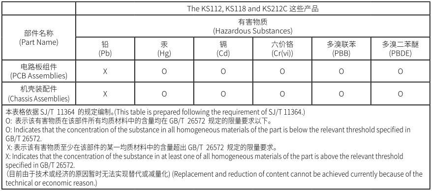
RoHS Statements
These products are in compliance with “China RoHS” directives per GB/T26572. The following table is provided for product use in China and its territories:
Warranty
For a copy of the QSC limited warranty visit the QSC website at www.qsc.com
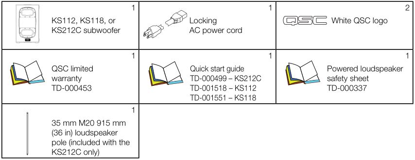
Package Contents
KS112 / KS212C Features
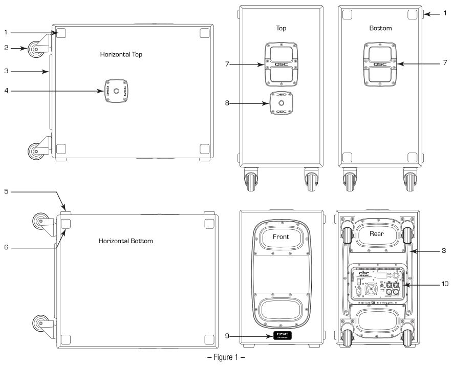
1. Alignment cups for stacking2. Four low-noise, heavy-duty casters3. Amplifier protection rails4. M20 threaded socket for 35 mm loudspeaker pole5. Slip-resistant feet – four on the bottom6. Slip-resistant feet – four on the side7. Cast aluminum handles8. M20 threaded socket for 35 mm loudspeaker pole9. Front power LED10. Amplifier power module and controls
KS118 Features

1. Alignment cups for stacking2. Four low-noise, heavy-duty casters3. Amplifier protection rails4. M20 threaded socket for 35 mm loudspeaker pole5. Slip-resistant feet – four on the bottom6. Slip-resistant feet – four on the side7. Cast aluminum handles8. Front power LED9. Amplifier power module and controls
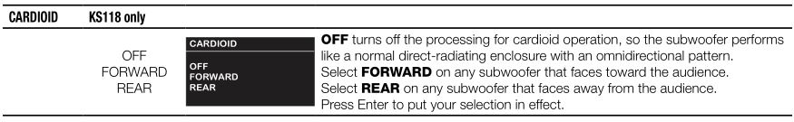
About Cardioid Subwoofer Radiation
The term cardioid refers to a heart-shaped coverage pattern of an audio device. For example, a cardioid microphone is most sensitive at the front (on-axis), and least at the rear (180 degrees off-axis). A cardioid subwoofer operates the same way and is loudest at the front and quietest at the rear.
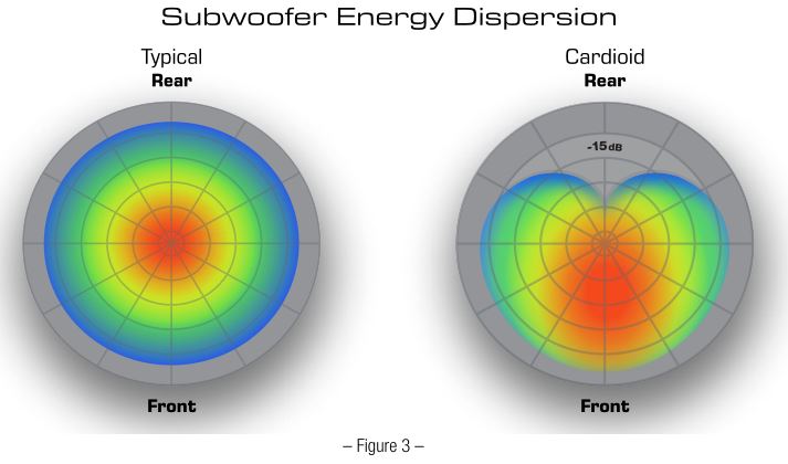
Low frequency energy from a conventional subwoofer is effectively omnidirectional below 200 Hz. This is because the directivity of the subwoofer is related to the ratio of its size to the length of the sound wave it produces. The length of the sound wave is inversely proportional to its frequency, and therefore when the low frequency waves are much longer than the dimensions of the subwoofer transducer and enclosure, the radiation pattern becomes more equal in all directions, including to the sides and back.
A cardioid subwoofer arrangement employs both front- and rear-firing woofers. Some clever use of spacing, delay, and polarity produces cancellation in the rear-firing energy and reinforcement in the forward-firing energy. Historically, creating cardioid subwoofer arrays has required the user to make complicated calculations involving physical spacing and signal processing. Two QSC subwoofer models make those calculations unnecessary.
KS212CThe KS212C is powered by a dual 1800-watt Class D amplifier and incorporates dual 12-inch long-excursion drivers that are each arranged in a sixth-order bandpass chamber. QSC’s latest DSP technology performs the complex processing that makes these mirrored components interact at the rear of the enclosure to produce a desirable cancellation, while simultaneously interacting at the front of the enclosure to produce equally desirable summation. As a result, the output pattern is a cardioid shape, with 15 dB higher level at the front than at the rear. To put this into perspective, 15 dB is equivalent to the difference between 30 watts of power and 1000 watts.
KS118The KS118 is a very high output active subwoofer, powered by a 3600-watt Class D amplifier driving a single 18-inch direct radiating driver. Its on-board DSP menu offers the option of arraying two or more units in a forward/backward cardioid arrangement with 15 dB of rearward rejection. From the subwoofers’ Cardioid menu, select Forward for the units facing the audience and Rear for the ones facing away. This also allows side-by-side or ground-stacked setups.
KS212C Applications and Installation
![]() WARNING: The KS212C subwoofer is not suitable for flying or suspension.
WARNING: The KS212C subwoofer is not suitable for flying or suspension.
Before placing, installing, or mounting a subwoofer check all hardware, cabinets, transducers, brackets, and associated equipment for damage. Missing, corroded, deformed, or non-load-rated components could significantly weaken the installation or placement and severely reduce the safety of the installation if left uncorrected. Use only hardware that is rated for the loading conditions of the installation as well as any possible short-term overloading.
Never exceed the load rating of the hardware or equipment.
Consult a licensed professional engineer regarding physical equipment installation. Understand and follow all local, state, and national regulations regarding the safety and operation of loudspeakers and related equipment.
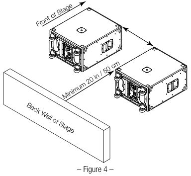
![]() IMPORTANT: To maintain the acoustic properties of the KS212C subwoofer do not place the unit closer than 50 cm (20 in) from a wall or other object that would reflect sound waves.
IMPORTANT: To maintain the acoustic properties of the KS212C subwoofer do not place the unit closer than 50 cm (20 in) from a wall or other object that would reflect sound waves.
Placement of the KS212CMake sure that the KS212C sub is placed no closer than 20 inches (50 cm) to the back wall of the stage. Side-by-side KS212C subs should be at least 20 inches (50 cm) away from each other.
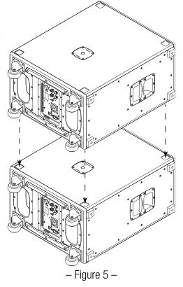
Stacking the KS212CKS212C subwoofers can stack in a horizontal orientation. The four rubber feet on the top subwoofer fit perfectly into the four cups on the bottom one (Figure 5). Do not stack more than two KS212C subwoofers because it will reduce rear attenuation.
- One subwoofer: 15 dB front-to-rear attenuation at 70 Hz
- Two subwoofers stacked: 12.5 dB front-to-rear attenuation at 70 Hz
- Three subwoofers stacked: 10 dB front-to-rear attenuation at 70 Hz
A stack of two subwoofers can support a loudspeaker, including a pole-mounted one.
![]() WARNING: Do not stack the KS212C units in a vertical orientation.
WARNING: Do not stack the KS212C units in a vertical orientation.
KS112 Applications and Installation
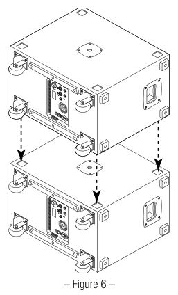
Stacking the KS112KS112 subwoofers can stack in a horizontal orientation. The four rubber feet on the top subwoofer fit perfectly into the four cups on the bottom one (Figure 6).
![]() WARNING: The KS112 subwoofer is not suitable for flying or suspension.
WARNING: The KS112 subwoofer is not suitable for flying or suspension.
Before placing, installing, or mounting a subwoofer check all hardware, cabinets, transducers, brackets, and associated equipment for damage. Missing, corroded, deformed, or non-load-rated components could significantly weaken the installation or placement and severely reduce the safety of the installation if left uncorrected. Use only hardware that is rated for the loading conditions of the installation as well as any possible short-term overloading.
Never exceed the rating of the hardware or equipment.
Consult a licensed professional engineer regarding physical equipment installation. Understand and follow all local, state, and national regulations regarding the safety and operation of loudspeakers and related equipment.
WARNING: Do not stack the KS112 units in a vertical orientation.
KS118 Applications and Installation
The KS118 subwoofer can be used as a single low-frequency acoustic source or in multiples for more coverage and lowfrequency energy. Single-subwoofer applications typically support a stereo pair of top loudspeakers. For most even coverage, place the subwoofer centrally between the pair, if it is possible. It is often necessary, though, to place the subwoofer off to the side, which will usually produce satisfactory results. Placing subwoofers to the left and right sides of a stage is often convenient, but it tends to create a concentration of bass energy up the middle of the audience area, often nicknamed “Power Alley.” To prevent this, try clustering the subwoofers in the middle or spread them across the front of the stage.
![]() WARNING: The KS118 subwoofer is not suitable for flying or suspension.
WARNING: The KS118 subwoofer is not suitable for flying or suspension.
Cardioid Configurations
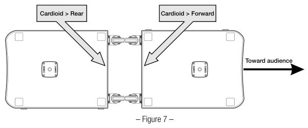
Two or more KS118 subwoofers can be arranged and configured to produce a cardioid radiation pattern very simply, with no complex calculations or processing settings required. The processing necessary for cardioid operation is already programmed into each KS118 subwoofer’s DSP. On each subwoofer facing forward (toward the audience), select FORWARD on the Cardioid menu. On each subwoofer facing away from the audience, select REAR on the Cardioid menu. Put the same audio signal into both subwoofers and set the same gain on each one.
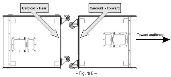
BEST: Back-to-back
Placing the subwoofers backto-back offers the best cardioid performance, with 15 dB of sound attenuation to the rear. Figure 7 is a top view of two KS118 subwoofers oriented vertically and placed backto-back. Figure 8 also is a top view of a back-to-back arrangement, but with the subwoofers oriented horizontally.
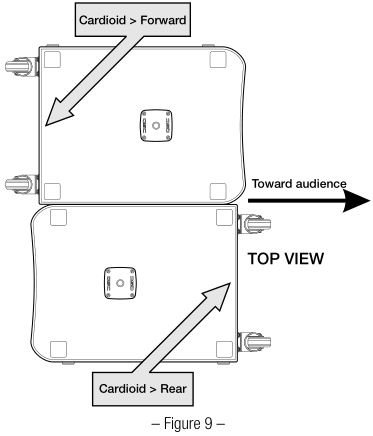
 GOOD: Side-by-sidePlacing the KS118 subwoofers side-by-side (Figure 9) may save space but creates a less precise cardioid pattern.
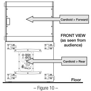
BETTER: StackedStacking two KS118 subwoofers is similar to the side-by-side arrangement. Figure 10 is a front view. Place the rear-facing subwoofer on the bottom.
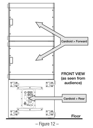
Three-box cardioid systemsA three-box array, with two forwardfacing and one facing to the rear, gives additional acoustic output to the front but with slightly less optimal rear attenuation.Figure 11 is a top view of a back-toback three-box array.Figure 12 is a front view of a stacked three-box array. Use the bottom subwoofer as the rearfacing one.

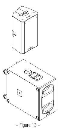
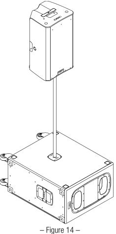
Pole-Mounting Loudspeakers over a Subwoofer
![]() NOTE: Figures 13 and 14 depict the KS212C but the KS112 has similar pole-mounting features. See the tables below for individual requirements.
NOTE: Figures 13 and 14 depict the KS212C but the KS112 has similar pole-mounting features. See the tables below for individual requirements.
The KS112 and KS212C Subwoofers are equipped with two M20 threaded sockets: one on the top, and one on the side. The KS118 has a single M20 threaded socket.
Figure 13 shows a KS Series Subwoofer in a vertical orientation with a K.2 Series loudspeaker mounted above.
Figure 14 shows a KS Series Subwoofer in a horizontal orientation with a K.2 Series loudspeaker mounted above.
Use the tables below to determine which poles are safe to use with the various CP, KW, KLA, K.2, and K Series loudspeakers and your KS Series Subwoofer in a horizontal or vertical orientation.
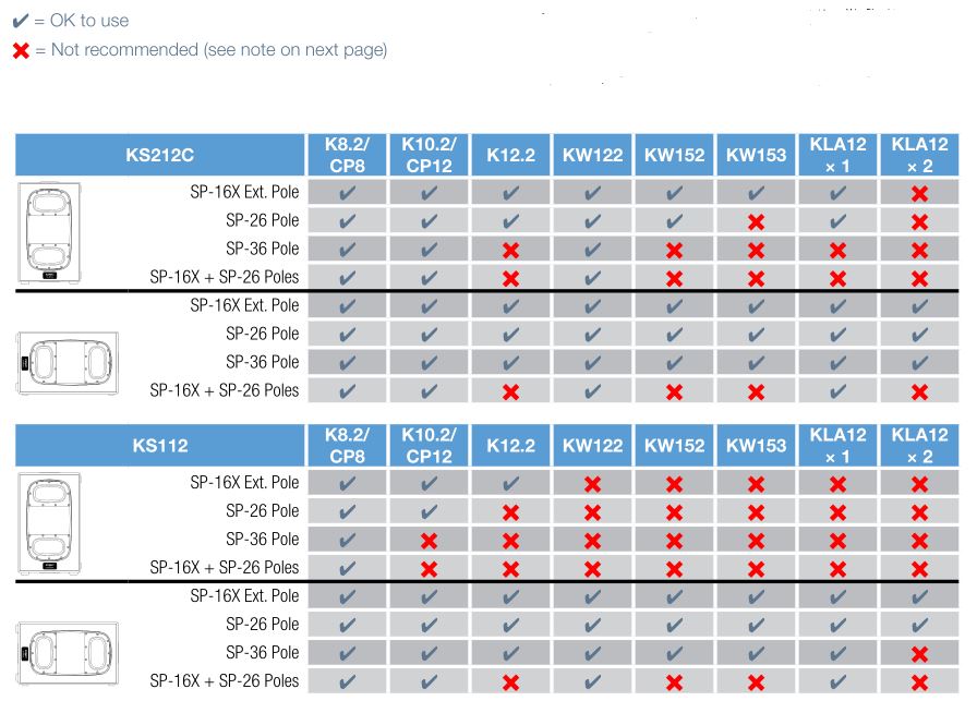
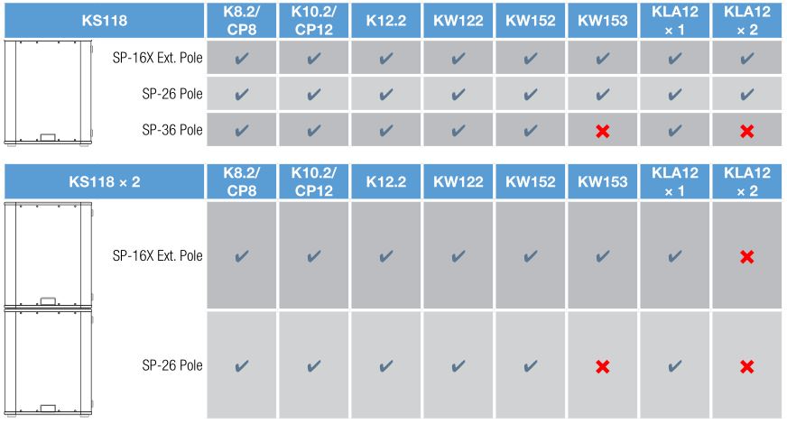
![]() NOTE: Do not use the configurations marked by a red X (6) unless the subwoofer or subwoofers are properly secured or restrained (Figure 15) to prevent them leaning more than 10 degrees in any direction.
NOTE: Do not use the configurations marked by a red X (6) unless the subwoofer or subwoofers are properly secured or restrained (Figure 15) to prevent them leaning more than 10 degrees in any direction. 
![]() WARNING: Do not fly or suspend any KS Series subwoofer. It is not intended or equipped for flying or suspension. Use only on a flat surface, such as a floor or stage.
WARNING: Do not fly or suspend any KS Series subwoofer. It is not intended or equipped for flying or suspension. Use only on a flat surface, such as a floor or stage.
Cooling
The KS Series subwoofers contain an internal power amplifier that produces heat. Allow a minimum of 15 cm (6 inches) clearance around the cabinet for convection cooling. Keep anything that might restrict airflow away from the rear of the enclosure (i.e draperies, walls, etc.)
![]() CAUTION: Do not operate the subwoofer with its amplifier module exposed to direct sunlight because overheating will cause its protection circuitry to reduce its maximum output. For full performance to specification keep the ambient temperature to below 50° C (122° F). KS Series subwoofer enclosures are not weatherproof, so do not install them where they will be exposed to rain or other water sources. Do not install outdoors without also protecting them from the elements.
CAUTION: Do not operate the subwoofer with its amplifier module exposed to direct sunlight because overheating will cause its protection circuitry to reduce its maximum output. For full performance to specification keep the ambient temperature to below 50° C (122° F). KS Series subwoofer enclosures are not weatherproof, so do not install them where they will be exposed to rain or other water sources. Do not install outdoors without also protecting them from the elements.
AC Mains
See Figure 16.
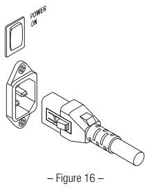
AC Mains DisconnectionUse the power switch to turn the amplifier off. Unplug the AC mains cord from the power source. The subwoofer has a V-LOCK latching IEC connector system; press the yellow button on the IEC plug to release the cord from the socket. Grasp the plastic body of the IEC connector to pull it out; do not pull on the cord.
Turning Your KS Series Subwoofers OnConnect the AC power cord to the IEC socket on the back of the amplifier. Make sure it is fully inserted. The V-LOCK power cord has a special latching feature to prevent unintentional detachment. The IEC cable plug and chassis socket are both blue so you can easily identify the KS subwoofer cord. If the cord is lost or damaged, a standard IEC power cord of 18 AWG/1 mm² or larger may be used in its place, though it will not have the latching system. Replacement V-LOCK cords are available from QSC.
![]() NOTE: Make sure that the AC power switch is OFF before connecting the AC power cord to the AC source.
NOTE: Make sure that the AC power switch is OFF before connecting the AC power cord to the AC source.
Connect the AC power cord to the facility’s AC outlet. The amplifier modules are equipped with a universal power supply that can use AC power voltages ranging from 100 to 240 VAC at 50 60 Hz.
![]() WARNING: Use only the power cable that is appropriate for your location.
WARNING: Use only the power cable that is appropriate for your location.
Power SwitchUse the rocker switch to apply AC mains power to the amplifier. When the amplifier is on, the blue POWER indicator LED comes on.
Rear POWER Indicator LEDIf the LED does not come on within 3 seconds after the amplifier module is turned on, verify that the power cord is properly connected to both the subwoofer and the AC mains outlet. Make sure the outlet is functioning properly, too.
![]() NOTE: If the power cord is good and the outlet is operating properly yet the subwoofer does not turn on, it may require servicing. Contact QSC Technical Services Group.
NOTE: If the power cord is good and the outlet is operating properly yet the subwoofer does not turn on, it may require servicing. Contact QSC Technical Services Group.
System Power SequencingProper power sequencing at turn on and turn off can help prevent audible thumps, clicks, and other noises in the system. Always follow the rule that loudspeakers are last on and first off.
Turn-On Sequence:
- Turn down the main faders (or other output level control) of the mixer (or other audio source) to minimum.
- Turn on all the source devices and processors (CD players, mixers, instruments, etc.).
- Turn on the KS Series subwoofers.
- Turn on the top loudspeakers.
- Bring up the faders or level controls on the mixer.
Turn-Off Sequence:
- Turn off the top loudspeakers.
- Turn off the KS Series subwoofers
- Turn off all audio source devices and processors.
Block Diagram
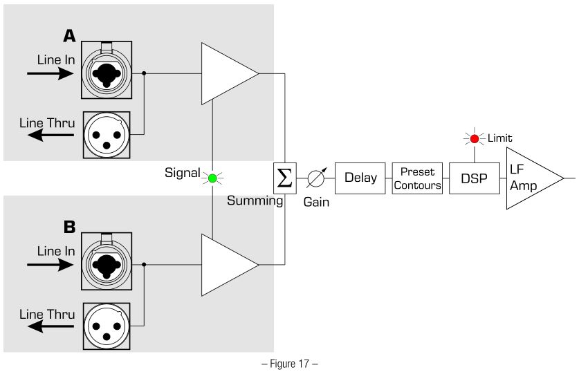
Inputs and Outputs
The KS Series subwoofer amplifier module has two female XLR / ¼-inch combination inputs and two corresponding pass-through male XLR outputs.See Figure 18.
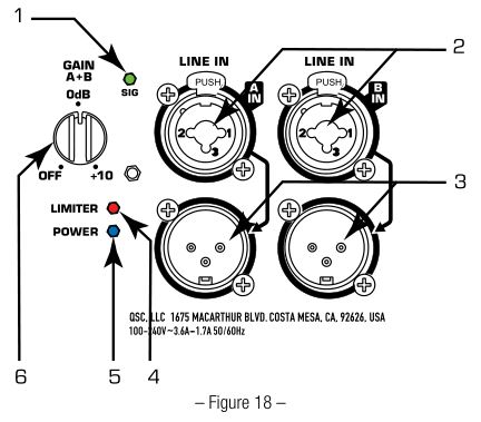
- SIG LED (green) – indicates that a signal is present on Input A or B or both. When it is not on, there is either no signal or it is too low to detect.
- CHANNEL A and B INPUTS – XLR – ¼-inch combination connector for full-range line-level balanced or unbalanced audio signals.
- CHANNEL A and B PASS-THROUGH CONNECTORS – Use these to daisy-chain full-range audio signals to other loudspeakers or to other audio equipment.
- LIMITER LED (red) – comes on when the module activates its built-in protective limiter. The limiter prevents damage to the amplifier and transducer—for example, if the amplifier output signal level is too high or the module is running too hot.
- POWER LED (blue) – shows that the amplifier module is turned on.
- GAIN knob – for adjusting sensitivity of inputs A and B, whose summed signals feed the power amplifier section.
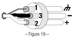
Balanced Inputs
Connect the XLR plug as shown in Figure 19.

Connect the TRS (Tip-Ring-Sleeve) plug as shown in Figure 20. Do not use a TS (TipSleeve) plug with a balanced signal.

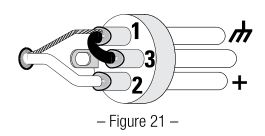
Unbalanced Inputs
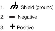
Connect the XLR plug as shown in Figure 21. (Jumper pins 1 and 3.)
Connect the TRS or TS plug as shown in Figure 22.

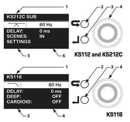
The KS Series subwoofers feature a multi-function digital display for control and selection of various subwoofer functions, including scenes, crossover, and delay.
Display Introduction
- Home Screen Displays the model number and the main functionality headings. A light background with black text highlights the menu item selected.
- Exit or “go back” button press to return to the previous screen or menu level.
- Enter button confirm a selected parameter or open the selected menu item.
- Selector knob move to another menu item, or change a selected parameter.
- Left column displays the parameter name. 6. Right column displays the current state of the parameter.
Navigation Example
To set delay–for example, to configure a time-aligned satellite loudspeaker supplementing the main audio system:
- Turn the knob (4) clockwise to select DELAY.
- Press the Enter button (3) to access the DELAY submenu.
- With the knob, set the desired amount of delay (displayed in ms, feet and meters simultaneously).
- Press the Enter button to confirm the setting and return to the main menu.
Menu Listing
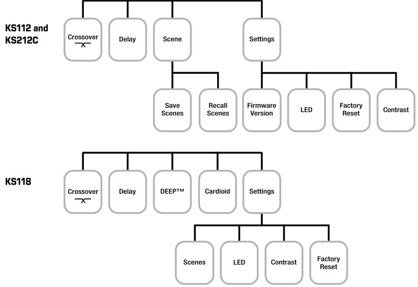 Menu Listing
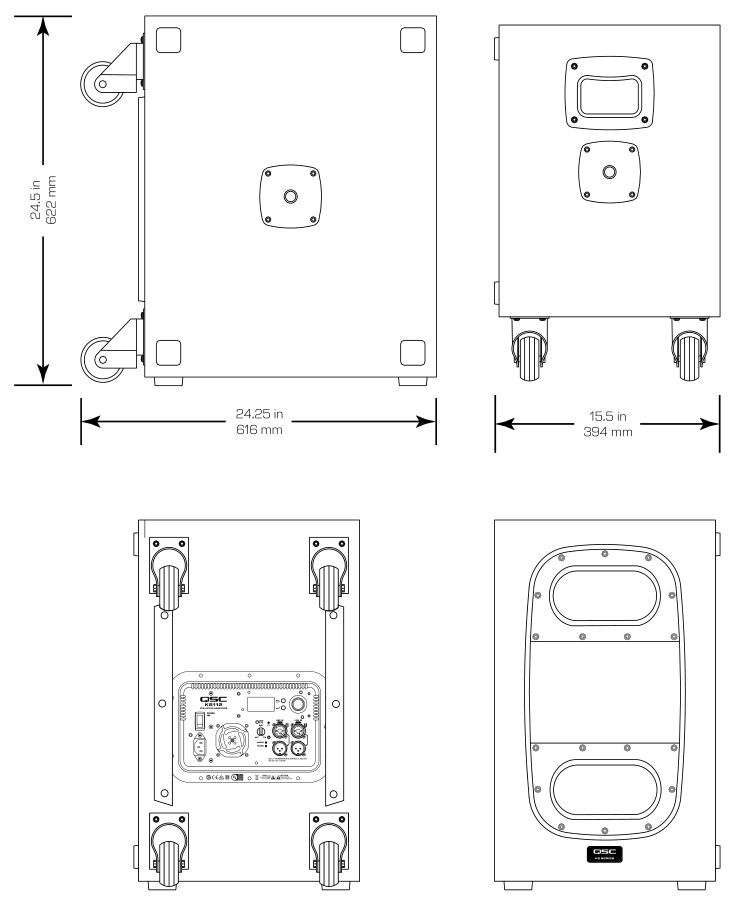
KS112 Dimensions
KS212C Dimensions
 KS212C Dimensions
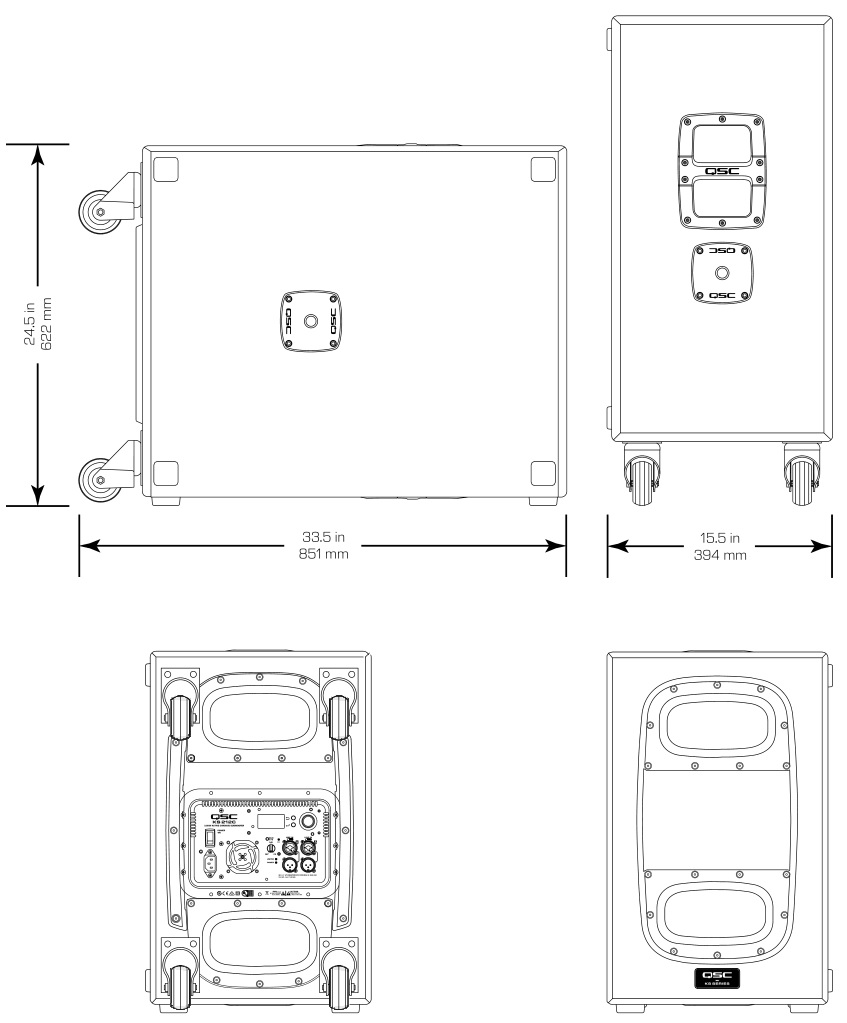
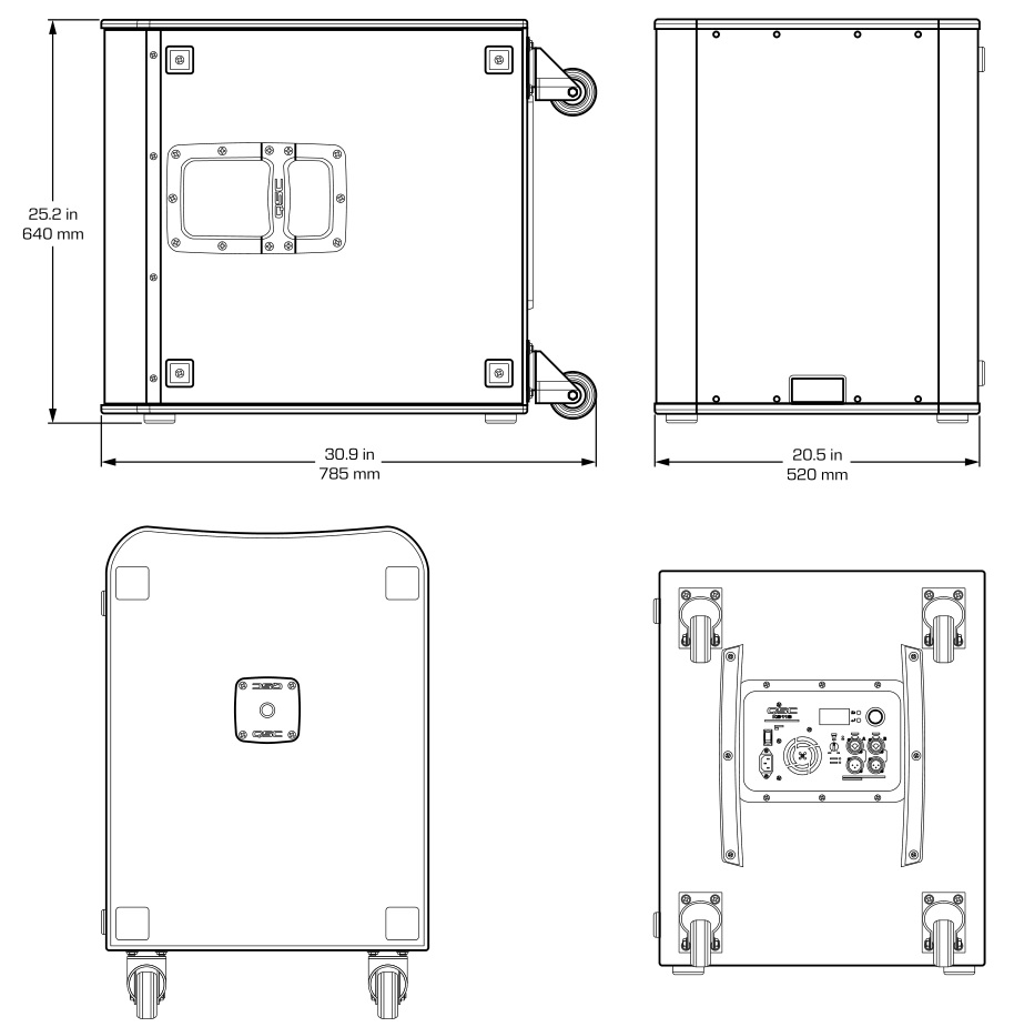
KS118 Dimensions
Specifications

![]() NOTE: Specifications subject to change without notice.
NOTE: Specifications subject to change without notice.
![]()
Mailing Address:QSC, LLC1675 MacArthur BoulevardCosta Mesa, CA 92626-1468 U.S.Main Number: +1.714.754.6175World Wide Web: www.qsc.com
Sales & Marketing:Voice: +1.714.957.7100 or toll free (U.S. only) 800.854.4079FAX: +1.714.754.6174E-mail: [email protected]
QSC Technical Services1675 MacArthur Blvd.Costa Mesa, CA 92626 U.S.Tel: 800.772.2834 (U.S. only)Tel: +1.714.957.7150FAX: +1.714.754.6173[email protected]
© Copyright 2019, QSC, LLC. QSC® is a registered trademark of QSC, LLC, “QSC” and the QSC logo are registered with the U.S. Patent and Trademark Office. All trademarks are the property of their respective owners.http://patents.qsc.com.
References
[xyz-ips snippet=”download-snippet”]