![]() QubinoFlush Dimmer 0-10VSKU: GOAEZMNHVD107-10-2020 09:52
QubinoFlush Dimmer 0-10VSKU: GOAEZMNHVD107-10-2020 09:52
Quickstart
This is a secure 10V Dimmer for Europe. To run this device please connect it to your mains power supply. To add this device to your network execute thefollowing action:
- press service button S for more than 2 seconds or
- press push button I1 three times within 3s (3 times change switch state within 3 seconds).
Important safety information
Please read this manual carefully. Failure to follow the recommendations in this manual may be dangerous or may violate the law. The manufacturer, importer, distributor and seller shall not be liable for any loss or damage resulting from failure to comply with the instructions in this manual or any other material. Use thisequipment only for its intended purpose. Follow the disposal instructions. Do not dispose of electronic equipment or batteries in a fire or near open heat sources.

What is Z-Wave?
Z-Wave is the international wireless protocol for communication in the Smart Home. This device is suited for use in the region mentioned in the Quickstart section-Wave ensures reliable communication by reconfirming every message (two-way communication) and every mains powered node can act as a repeater for other nodes (meshed network) in case the receiver is not in direct wireless range of the transmitter.This device and every other certified Z-Wave device can be used together with any other certified Z-Wave device regardless of brand and origin as long as both are suited for the same frequency range.If a device supports secure communication it will communicate with other devices secure as long as this device provides the same or a higher level of security. Otherwise, it will automatically turn into a lower level of security to maintain backward compatibility.For more information about Z-Wave technology, devices, white papers, etc. please refer to www.z-wave.info.
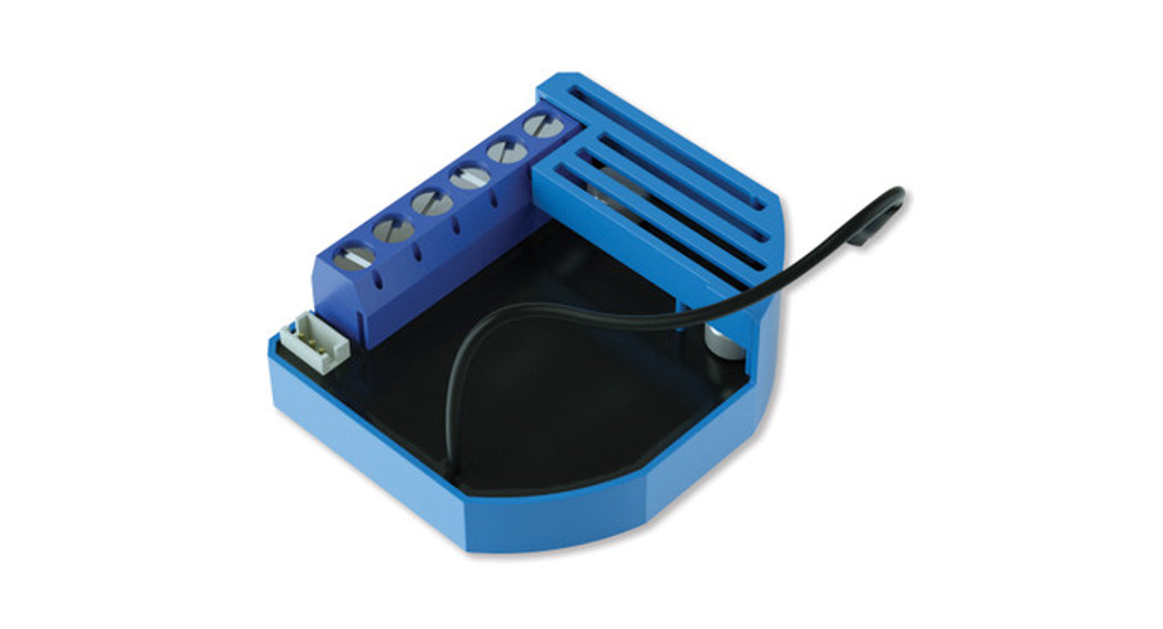
Product Description
Universal dimmer module with standard 0-10V output and a multi-function input, which may be a push-button/switch, a potentiometer or 0-10V signal.
- Push-button (mono stable switch)
- Bi stable switch
- Potentiometer
- 0-10V input (requires external source)
Prepare for Installation / Reset
Please read the user manual before installing the product.In order to include (add) a Z-Wave device to a network, it must be in a factory default state. Please make sure to reset the device into factory default. You can dby performing an Exclusion operation as described below in the manual. Every Z-Wave controller is able to perform this operation however it is recommended http://manual.zwave.eu/backend/make.php?lang=en&sku=GOAEZMNHVD1
the primary controller of the previous network to make sure the very device is excluded properly from this network.
Reset to factory default
This device also allows being reset without any involvement of a Z-Wave controller. This procedure should only be used when the primary controller is inoperable
- press service button S for more than 6 seconds or
- press push button I1 five times within 3s ( 5 times change switch state within 3 seconds) in the first 60 seconds after the module is connected to the power supply.
Safety Warning for Mains Powered Devices
ATTENTION: only authorized technicians under consideration of the country-specific installation guidelines/norms may do works with mains power. Prior to the assembly of the product, the voltage network has to be switched off and ensured against re-switching.
Installation
- Before the installation disconnect the power supply (1224VDC)
- Connect the module according to the electrical diagram.
- Locate the antenna far from metal elements (as far as possible).
- Do not shorten the antenna.
Note! Do not connect the module to loads exceeding recommended values. Connect the module only in accordance to the below diagrams. Improper connectionbe dangerous.
Electrical diagram
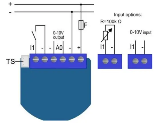
Notes for the diagram:1:12 – 24VDC
– :GND
AO: 0- 10VDC
l1: Input for push buttonismonpoontionster or 010J
TS Terminal lOrdignal temperature sensor (only for Flush Dimmer 0-10V module compatible digital temperature sensor. which must be ordered separately)
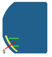
S: Service button (used to add or remove the module from the Z-Wave network)
NOTE: When connecting the temperature sensor to the module that has already been included, you have to exclude module first. Switch off the power supply, connect theand re-include the module.
Inclusion/Exclusion
On factory default, the device does not belong to any Z-Wave network. The device needs to be added to an existing wireless network to communicate with devices of this network. This process is called Inclusion.Devices can also be removed from a network. This process is called Exclusion. Both processes are initiated by the primary controller of the Z-Wave network. a controller is turned into exclusion respective inclusion mode. Inclusion and Exclusion is then performed doing a special manual action right on the device.Inclusion
- press service button S for more than 2 seconds or
- press push button I1 three times within 3s (3 times change switch state within 3 seconds).
Exclusion
- press service button S for more than 6 seconds or
- press push button I1 five times within 3s ( 5 times change switch state within 3 seconds) in the first 60 seconds after the module is connected to the powersupply.
Auto-Inclusion
Besides the standard inclusion, these devices support the so-called auto inclusion. Right after powering up the device remains in an inclusion state and can be in(any) gateway without further actions on the device itself. The auto inclusion mode will time out after some time.
Quick trouble shooting
Here are a few hints for network installation if things don’t work as expected.
- Make sure a device is in a factory reset state before including it. In doubt exclude before include.
- If inclusion still fails, check if both devices use the same frequency.
- Remove all dead devices from associations. Otherwise, you will see severe delays.
- Never use sleeping battery devices without a central controller.
- Don’t poll FLIRS devices.
- Make sure to have enough mains powered devices to benefit from the meshing
Association – one device controls another device
Z-Wave devices control other Z-Wave devices. The relationship between one device controlling another device is called association. In order to control a diffe device, the controlling device needs to maintain a list of devices that will receive controlling commands. These lists are called association groups and they are related to certain events (e.g. button pressed, sensor triggers, …). In case the event happens all devices stored in the respective association group will receive same wireless command, typically a ‘Basic Set’ Command.
Association Groups:
| Group Number | Maximum Nodes | Description |
| 1 | 1 | Lifeline |
| 2 | 16 | basic on/off |
| 3 | 16 | start level change/stop level change |
| 4 | 16 | multilevel set |
| 5 | 16 | multilevel sensor report (triggered at the change of analog sensor) |
| 6 | 16 | multilevel sensor report (triggered at the change of temperature sensor) |
Configuration Parameters
Z-Wave products are supposed to work out of the box after inclusion, however certain configuration can adapt the function better to user needs or unlock furthenhanced features.IMPORTANT: Controllers may only allow configuring signed values. In order to set values in the range 128 … 255 the value sent in the application shall be the value minus 256. For example: To set a parameter to 200 it may be needed to set a value of 200 minus 256 = minus 56. In the case of a two-byte value, the same applies Values greater than 32768 may be needed to be given as negative values too.
Parameter 1: Input switch typeSize: 1 Byte, Default Value: 0
| Setting | Description |
| 0 | mono-stable switch type (push button) |
| 1 | bi-stable switch type |
Parameter 5: Working modeWith this parameter is possible to change the module presentation on the user interface.NOTE: After parameter change, first exclude a module (without setting parameters to default value) then wait for at least 30s and then re-include the module!Size: 1 Byte, Default Value: 0
| Setting | Description |
| 0 | Dimmer mode |
| 1 | Switch mode |
Parameter 10: Activate / deactivate functions ALL ON / ALL OFFSize: 2 Byte, Default Value: 255
| Setting | Description |
| 255 | ALL ON active, ALL OFF active. |
| 0 | ALL ON is not active, ALL OFF is not active |
| 1 | ALL ON is not active, ALL OFF active |
| 2 | ALL ON active, ALL OFF is not active DIN Dimmer module responds to commands ALL ON / ALL OFF that masent by the main controller or by another controller belonging to the system. |
Parameter 11: Automatic turning off the output after a set timeSize: 2 Byte, Default Value: 0\
| Setting | Description |
| 0 | Auto OFF disabled |
| 1 – 32536 | 1 second – 32536 seconds Auto OFF enabled with define time, step is 1 second. |
Parameter 12: Automatic turning on output after set timeSize: 2 Byte, Default Value: 0
| Setting | Description |
| 0 | Auto ON disabled |
| 1 – 32535 | 1 second – 32535 seconds Auto ON enabled with define time, step is 1 second |
Parameter 21: Enable/Disable Double click functionIf the Double click function is enabled, a fast double click on the push button will set dimming power at maximum dimming value.Size: 1 Byte, Default Value: 0
| Setting | Description |
| 0 | Auto ON disabled |
| 1 | double click enabled |
Parameter 30: Saving the state of the device after a power failureSize: 1 Byte, Default Value: 0
| Setting | Description |
| 0 | DIN Dimmer module saves its state before power failure (it returns to the last position saved before a powerfailure). |
| 1 | DIN Dimmer module does not save the state after a power failure, it returns to off position. |
Parameter 40: Power reporting in Watts on power changeSet value means percentage, set value from 0 – 100=0% – 100%.NOTE: if power changed is less than 1W, the report is not sent (pushed), independent of the percentage set. Size: 1 Byte, Default Value: 5
| Setting | Description |
| 0 | reporting disabled |
| 1 -100 | 1% – 100% Reporting enabled. Power report is sent (push) only when actual power in Watts in real-time chan for more than a set percentage comparing to previous actual power in Watts, step is 1%. |
Parameter 42: Power reporting in Watts by time intervalSet value means time interval (0 – 32767) in seconds when the power report is sent.Size: 2 Byte, Default Value: 0
| Setting | Description |
| 0 | reporting disabled |
| 1 – 32767 | 1 second – 32767 seconds. Reporting enabled. Power report is sent with time interval set by entered value.Please note, that too fast reporting can cause too much Z-Wave traffic resulting in Z-Wave poor response |
Parameter 60: Minimum dimming valueNOTE: The minimum level may not be higher than the maximum level! 1% min. dimming value is defined by Z-Wave multilevel device classSize: 1 Byte, Default Value: 1
| Setting | Description |
| Jan-98 | 1% – 98%, step is 1%. Minimum dimming values is set by entered value. |
Parameter 61: Maximum dimming valueNOTE: The maximum level may not be lower than the minimum level! 99% max. dimming value is defined by the Z-Wave multilevel device class.Size: 1 Byte, Default Value: 99
| Setting | Description |
| 2 – 99 | 2% – 99%, step is 1%. Maximum dimming values is set by entered value. |
Parameter 65: Dimming time (soft on/off)Set value means a time of moving the DIN Dimmer between min. and max. dimming values by a short press of push-button I or controlled through UI (BasicSet).Size: 2 Byte, Default Value: 100
| Setting | Description |
| 50 – 255 | 500 mseconds – 2550 seconds (2,55s), step is 10 seconds |
Parameter 66: Dimming time when key pressedTime of moving the DIN Dimmer between min. and max dimming values by continues hold of push-button I or associated device.Size: 2 Byte, Default Value: 3
| Setting | Description |
| 1 – 255 | 1 second – 255 seconds |
Parameter 67: Ignore start levelThis parameter is used with association group 3. A receiving device SHOULD respect the start level if the Ignore Start Level bit is 0. A receiving device MUST ignthe start level if the Ignore Start Level bit is 1.Size: 1 Byte, Default Value: 0
| Setting | Description |
| 0 | respect start level |
| 1 | ignore start level |
Parameter 68: Dimming durationThis parameter is used with association group 3. The Duration field MUST specify the time that the transition should take from the current value to the new target value. A supporting device SHOULD respect the specified Duration value.Size: 1 Byte, Default Value: 0
| Setting | Description |
| 0 | dimming duration according to parameter 66 |
| 1 – 127 | from 1 to 127 seconds |
Parameter 110: Temperature sensor offset settingsSet value is added or subtracted to the actual measured value by the sensor.Size: 2 Byte, Default Value: 32536
| Setting | Description |
| 1 – 100 | value from 0.1 °C to 10.0 °C is added to the actual measured temperature. |
| 1001 – 1100 | value from -0.1 °C to -10.0 °C is subtracted from the actual measured temperature. |
Parameter 120: Digital temperature sensor reportingIf the digital temperature sensor is connected, the module reports measured temperature on temperature change defined by this parameter.Size: 1 Byte, Default Value: 5
| Setting | Description |
| 0 | reporting disabled |
| 1 – 127 | 0,1°C – 12,7°C, step is 0,1°C |
Parameter 250: Unsecure/Secure Inclusion (Version 2.04 or higher)Size: 1 Byte, Default Value: 0
| Setting | Description |
| 0 | Unsecure |
| 1 | Secure |
Technical Data
| Dimensions | 41,8×36,8×15,4 mm |
| Weight | 28 gr |
| Hardware Platform | ZM5202 |
| EAN | 3.83E+12 |
| IP Class | IP IP20 |
| Voltage | 12-24V DC |
| Device Type | 10V Dimmer |
| Generic Device Class | Multilevel Switch |
| Firmware Version | 2.04 |
| Z-Wave Version | 4.22 |
| Certification ID | ZC10-17025424 |
| Z-Wave Product Id | 0x0159.0x0001.0x0053 |
| Frequency | Europe – 868,4 Mhz |
| Maximum transmission power | 5 mW |
Supported Command Classes
- Basic
- Device Reset Locally
- Zwaveplus Info
- Manufacturer Specific
- Powerlevel
- Version
- Security
- Switch Binary
- Switch Multilevel
- Switch All
- Association Grp Info
- Configuration
- Association
- Multi-Channel Association
Explanation of Z-Wave specific terms
- Controller — is a Z-Wave device with capabilities to manage the network. Controllers are typically Gateways, Remote Controls or battery operated wall controllers.
- Slave — is a Z-Wave device without capabilities to manage the network. Slaves can be sensors, actuators, and even remote controls.
- Primary Controller — is the central organizer of the network. It must be a controller. There can be only one primary controller in a Z-Wave network.
- Inclusion — is the process of adding new Z-Wave devices into a network.
- Exclusion — is the process of removing Z-Wave devices from the network.
- Association — is a control relationship between a controlling device and a controlled device.
- Wakeup Notification — is a special wireless message issued by a Z-Wave device to announces that is able to communicate.
- Node Information Frame — is a special wireless message issued by a Z-Wave device to announce its capabilities and functions
 report this ad
(c) 2020 Z-Wave Europe GmbH, Antonstr. 3, 09337 Hohenstein-Ernstthal, Germany, All rights reserved, www.zwave.eu. The template is maintained by Z-WaveEurope GmbH. The product content is maintained by Z-Wave Europe GmbH, Support team, [email protected]. Last update of the product data: 2018-02-1915:16:39.http://manual.zwave.eu/backend/make.php?lang=en&sku=GOAEZMNHVD1
References
[xyz-ips snippet=”download-snippet”]