![]()
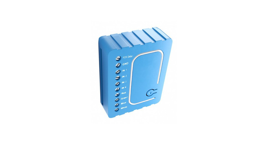
QubinoFlush RGBW DimmerSKU: GOAEZMNHWD1![]()
Quickstart
This is a Light Dimmer for Europe. To run this device please connect it to your mains power supply Include the R G B.W. color LED Dimmer into the 2- Wave network. press service Dutton 3 times in 2 seconds. If the device is properly included the green light will remain on.
Important safety information
Please read this manual carefully Failure to follow the recommendations in this manual may be dangerous or may violate the law of The manufacturer. importer. distributor and seller shall not be liable for any loss or damage resulting from failure to comply with the instructions in this manual or any other material. Use this equipment only for its intended purpose. Follow the disposal instructions. Do not dispose of electronic equipment or batteries in a fire or near open heat sources.
What is Z-Wave?
Z-Wave is the international wireless protocol for communication in the Smart Home. This device is suited for use in the region mentioned in the Quickstart section.Z-Wave ensures reliable communication by reconfirming every message (two-way communication) andevery mains powered node can act as a repeater for other nodes (meshed network) in case the receiver isnot in direct wireless range of the transm Mr_
This device and every other certified 2-Wave device can be used together with any other certified 2-Wave device regardless of brand and origin as long as both are suited for the same frequency range.
If a device supports secure communication it wins communicate with other devices secure as long as this device provides the same or a higher level of security. Otherwise, it will automatically turn into a lower level of security to maintain backward compatibility.For more information about Z-Wave technology. devices. white papers etc please refer to www.z-wave.info.

Product Description
Rubino Flush RGBW module is used to control RGELRGEIW strips and LED strips or bulbs to create countless color options and has 5 special scene effects. It can also control halogen lights and fans Its extremely small size allows for easy installation behind wan sockets and switches. Controlled devices may be powered by 12 or 24 VDC. All IN and OUT terminals may be user configured for LED control or 100 kf) signal readouts.
Prepare for Installation / Reset
Please read the user manual before installing the product_
In order to include (add) a 2-Wave device to a network, it must be in the factory default state. Please make sure to reset the device into factory default. You can do this by performing an Exclusion operation as described below in the manual. Every Z-Wave controller is able to perform this operation however it is recommended to use the primary controller of the previous network to make sure the very device is excluded properly from this network.
Reset to factory default
This device also allows being reset without any involvement of a 2-Wave controller. This procedure should only be used when the emery controller is inoperable.
Please note that re-including the product will reset the data to the default values. Use this procedure only in tile event that the network primary controller is missing or others-use inoperable.
Safety Warning for Mains Powered Devices
ATTENTION: only authorized technicians under consideration of the country-specific installation guickNineshorms may do works with mains power. Prior to the assembly of the product. the voltage network has to be switched off and ensured against re-switching.
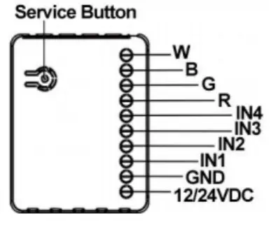
Installation
– Before the installation disconnect the power supply (12-24VDC)– Connect the module according to the electrical diagram.
Electrical Diagram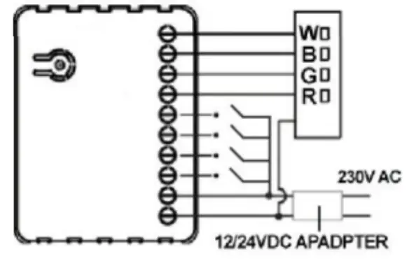
Notes for diagram:
| 12/24VDC – Power supply | IN4 – Potential free / 100KCI |
| GND – Power supply ground | R – Output assigned to IN1 |
| IN1 – Potential free / 100K0 | G – Output assigned to IN2 |
| IN2 – Potential free / 100K0 | B – Output assigned to IN3 |
| IN3 – Potential free / 100K0 | W – Output assigned to IN4 |
– Pull the antenna out of the holder– Locate the antenna far from metal elements (as far as possible).– Do not shorten the antenna.
Warning!
- The RGBW Controller is suggested to operate in low voltage circuits of 12VDC or 24VDC. Connecting a higher voltage load may result in RGBW Controller damage. Please refer to the following table.
The current of RGBW Strip Stranded Wire High current 18 AWG Low current 22 AWG - The RGBW Controller must be powered by the same voltage as the connected light source. I.e. if controlling the 12V LED strip, the module must be connected to a 12V power supply. Similarly, if controlling the 24V RGBW strip, the RGBW Controller must be powered by a 24V voltage supply.
- The RGBW Controller has 100KΩ input. There is no 100KΩ output. Output is controlled by PWM at 488Hz.
- The RGBW Controller must be powered by 12VDC or 24 VDC stabilized power supply with outputs load capacity matched to loads voltage.
- In the case of connecting long RGBW/RGB/LED strips voltage drops may occur, resulting in lower light brightness further from R/G/B/W outputs. To eliminate this effect it”s recommended to connect a few shorter strips in parallel connection instead of one long strip connected serially. The Maximum recommended wire length, used to connect R/G/B/W outputs with an RGBW/RGB/LED strip is 10 m. Observe connected loads manufacturer recommendations towards connection wire diameter.
- For the connection of IN1~IN4, it is suggested that you connect the 4 inputs individually to the same type of device. The devices can be as follows: the rotary switch, the toggle switch, or the push switch.
- When the Controller is damaged or lost, and you have already transferred the control function to an external control switch before, the product can be normally operated. In another case, please purchase a new Controller, press the Include/Exclude Button three times to exclude the device, and then include the device with the original installation steps, the device can be restored to normal operation. Please note that reincluding the product will reset the data to the default values. Use this procedure only in the event that the network primary controller is missing or otherwise inoperable.
Inclusion/Exclusion
On factory default, the device does not belong to any Z-Wave network. The device needs to be added to an existing wireless network to communicate with thedevices of this network. This process is called Inclusion.Devices can also be removed from a network. This process is called Exclusion. Both processes are initiated by the primary controller of the Z-Wave network. Thiscontroller is turned into exclusion respective inclusion mode. Inclusion and Exclusion are then performed doing a special manual action right on the device.InclusionInclude the R.G.B.W. color LED Dimmer into the Z-Wave network, press the service button 3 times in 2 seconds. If the device is properly included the green light will remain on.ExclusionExclude the Flush RGBW Dimmer into the Z-Wave network, press 3 times in 2 seconds. If the device is properly excluded, the green light will blink and data will be reset to the factory default values.Auto-InclusionBesides the standard inclusion, these devices support the so-called auto inclusion. Right after powering up the device remains in an inclusion state and can be included by (any) gateway without further actions on the device itself. The auto inclusion mode will time out after some time.
Product Usage
- Connect the R.G.B.W. Color LED Dimmer according to the wiring diagram.– First, connect RGBW strip, outputs (R,G,B,W) RGB/RGBW/LED diodes, halogen lights, or inputs (IN1~IN4).– Second, connect the power supply.If the device is properly connected, the RGBW strip will blink once. Note that the device must be powered by a dedicated stabilized power adapter.
- In the status of the factory default (Not Paired), the red light and green light will blink by turns, eg. red, green, red, green, etc..
- Include the R.G.B.W. Color LED Dimmer into the Z-wave network, press the service button 3 times in 2 seconds. If the device is properly included, the green light will remain on.
- Exclude the Flush RGBW Dimmer into the ZWave network, press 3 times in 2 seconds. If the device is properly excluded, the green light will blink and the data will be reset to the factory default values.
- Please pull out the antenna and keep it at 90 degrees to enhance the RF signals.
- Support auto inclusion: Install the device, connect with the power, and the auto inclusion function will work in about 2 minutes.
- Support remote exclusion: Through configuration setting. Please refer to the following table.
| IL) | Size | Value |
| 240 | 1 byte | 1 |
LED indication
| Status | LED Signal
Solid Red |
Remark |
| Not Paired | ||
| Paired up | Solid Green | |
| Inclusion | Blinking Green (Interval: 1 | Touch three times (Must release in 2 sec.) |
| Exclusion | Blinking Green (Interval: 1 | Touch three times (Must release in 2 sec.) |
| Auto inclusion | Blinking Green (Interval: 1sec.) | Connect/disconnect power to connect with Z-wave network |
| Hardware button | 1. Add device2. Delete device3. Restore to the default value4. Set association | |
| Input (11-14) | Control RGBW channel(I1:R -I4:W) |
| Input type | Remark |
| Momentary | Monostable or push-button switch |
| Toggle | Bistable switch |
| Toggle w/Memory | ON: Active for closing terminalsOFF: Active for opening terminals |
| Input operating mode | Remark |
| Normal | Each given switch key assigned to one output channel |
| Brightness | All channels are controlled together |
| Rainbow | transition through all colors .pectrum (Operates on RGB channels only) |
Quick troubleshooting
Here are a few hints for network installation if things don’t work as expected.
- Make sure a device is in a factory reset state before including. In doubt exclude before include.
- If inclusion still fails, check if both devices use the same frequency.
- Remove all dead devices from associations. Otherwise, you will see severe delays.
- Never use sleeping battery devices without a central controller.
- Don’t poll FLIRS devices.
- Make sure to have enough mains powered devices to benefit from the meshing
Association – one device controls another deviceZ-Wave devices control other Z-Wave devices. The relationship between one device controlling another device is called association. In order to control a different device, the controlling device needs to maintain a list of devices that will receive controlling commands. These lists are called association groups and they are always related to certain events (e.g. button pressed, sensor triggers, …). In case the event happens all devices stored in the respective association group will receive the same wireless command, typically a ‘Basic Set’ Command.
Association Groups:
| Group Number | Maximum Nodes | Description |
| 1 | 1 | Lifeline |
Configuration Parameters
Z-Wave products are supposed to work out of the box after inclusion, however, the certain configurations can adapt the function better to user needs or unlock further enhanced features.IMPORTANT: Controllers may only allow configuring signed values. In order to set values in the range 128 … 255 the value sent in the application shall be the desired value minus 256. For example: To set a parameter to 200 it may be needed to set a value of 200 minus 256 = minus 56. In the case of a two-byte value, the same logic applies: Values greater than 32768 may be needed to be given as negative values too.Parameter 1: Input switch typeNOTE: Please power cycle the device when the parameter is changed.Size: 1 Byte, Default Value: 1
| Setting | Description |
| 1 | bi-stable switch type |
| 2 | monostable (push button) switch type |
Parameter 2: Switch modeNOTE: Using this parameter, it is possible to select various modes of RGBW Dimmer operation.Size: 1 Byte, Default Value: 1
| Setting | Description |
| 1 | Normal Mode |
| 2 | Brightness Mode |
| 3 | Rainbow Mode |
Parameter 3: Auto scene mode setNOTE: Activation of the programmed scene changing color shades.Size: 1 Byte, Default Value: 0
| Setting | Description |
| 1 | Ocean |
| 2 | Lightning |
| 3 | Rainbow |
| 4 | Snow |
| 5 | Sun |
Parameter 4: Auto scene durationNOTE: Using this parameter, it is possible to change Auto scene mode duration.Size: 1 Byte, Default Value: 3
| Setting | Description |
| 1 – 127 | delay duration is from 1s to 127s |
| -127 | delay duration is from 1min. to 127min. |
Parameter 240: Remote exclusionSupport remote exclusion: Through configuration setting.Size: 1 Byte, Default Value: 0
| Setting | Description |
| 1 | Remote exclusion |
Technical Data
| Dimensions | 41x32x15 mm |
| Weight | 14 gr |
| Hardware Platform | ZM5101 |
| EAN | 3.83E+12 |
| IP Class | IP 20 |
| Voltage | 12 / 24V DC |
| Load | At 12V- 156W combined; At 24V- 312W combined |
| Device Type | Light Dimmer Switch |
| Generic Device Class | Multilevel Switch |
| Specific Device Class | Routing Multilevel Switch |
| Network Operation | Always On Slave |
| Firmware Version | 2.07 |
| Z-Wave Version | 4.18 |
| Certification ID | ZC10-17015398 |
| Z-Wave Product Id | 0159.0001.0054 |
| Frequency | Europe – 868,4 Mhz |
| Maximum transmission power | 5 mW |
Supported Command Classes
- Basic
- Switch Binary
- Switch Multilevel
- Switch Color
- Association Grp Info
- Device Reset Locally
- Zwaveplus Info
- Configuration
- Manufacturer Specific
- Powerlevel
- Firmware Update Md
- Association
- Version
Explanation of Z-Wave specific terms
Controller — is a Z-Wave device with capabilities to manage the network. Controllers are typically Gateways, Remote Controls, or battery-operated wall controllers.Slave — is a Z-Wave device without capabilities to manage the network. Slaves can be sensors, actuators, and even remote controls.Primary Controller — is the central organizer of the network. It must be a controller. There can be only one primary controller in a Z-Wave network.Inclusion — is the process of adding new Z-Wave devices into a network.Exclusion — is the process of removing Z-Wave devices from the network.Association — is a control relationship between a controlling device and a controlled device.Wakeup Notification — is a special wireless message issued by a Z-Wave device to announce that is able to communicate.manual.zwave.eu/backend/make.php?lang=en&sku=GOAEZMNHWD1Node Information Frame — is a special wireless message issued by a Z-Wave device to announce its capabilities and functions.
(c) 2020 Z-Wave Europe GmbH, Antonstr. 3, 09337 Hohenstein-Ernstthal,Germany, All rights reserved, www.zwave.eu. The template is maintained by Z-WaveEurope GmbH. The product content is maintained by Z-Wave EuropeGmbH, Support team, [email protected]. Last update of the product data: 2017-12-2714:35:13manual.zwave.eu/backend/make.php?lang=en&sku=GOAEZMNHWD126-10-2020
References
[xyz-ips snippet=”download-snippet”]