R TEC AUTOMATION Solar Panel Battery Charger

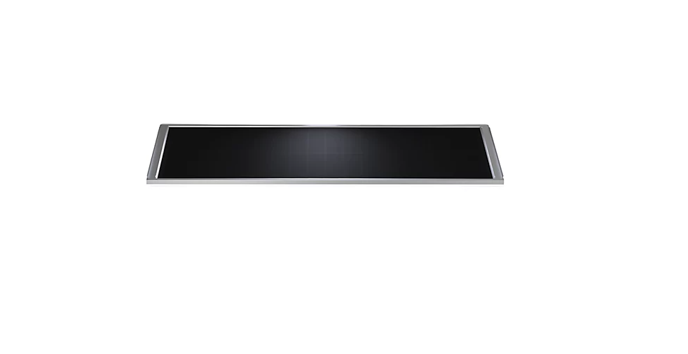
Solar Panel Battery Charger
Use the sun to your advantage with our R-TEC Automation® Solar Panel, even when Solar Panel is partially shaded.
When paired with our solar panel, Li-ion motors or battery packs remain powered by harnessing the natural energy of the sun. Sleek design allows for unobtrusive placement behind most headrails.
The charger uses industry leading, crystal technology to maximize sun ray absorption in a wide range of locations and orientations. Renewable power means motors stay running for longer, without the need for regular charging.
FEATURES

COMPLIANCE STATEMENT
This device complies with part 15 of the FCC Rules. Operation is subject to the following two conditions:
- This device may not cause harmful interference.
- This device must accept any interference received, including interference that may cause undesired operation.
TECHNICAL DATA / PACK CONTENTS
PRODUCT SPECIFICATIONS
|
Parameters |
Value | |
|
Max Output Power (Under 1 SUN – 1200W/m²) |
2.73 W | |
|
Round Connector |
Vmax |
12.6 V |
|
Imax |
220 mA | |
|
USB Connector |
Vmax |
5 V |
|
Imax |
300 mA | |
|
IP Rating |
IP40 |
KIT COMPONENTS
- Solar Panel
- L-Bracket – Aluminum
- Cable: Male Micro USB to Male Micro USB Connector Cable
- Cable: Male Barrel to Male 2 Pin SMR
- Alcohol Wipe Cloths (Twin Pack)
- Dual Lock Type 250 Fastener
- Slot & Screw Cover Stickers / Label Set


SAFETY
 WARNINGAny changes or modifications to this unit not expressly approved by the party responsible for compliance could void the user’s authority to operate the equipment. Incorrect installation can lead to serious injury and will void manufacturer’s liability and warranty
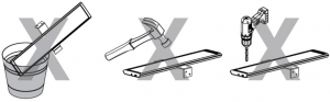
CAUTION
- Do not expose to moisture or extreme temperatures.
- Do not allow children to play with this device.
- Use or modification outside the scope of this instruction manual will void warranty.
- Installation and programming to be performed by a suitably qualified installer.
- For use within Li-ion Motors and rechargeable battery packs only.
- Do not cut power cables.
- Use only R-TEC Automation® hardware.
- NOT suitable for exterior application.
- Do not drill into Solar Panel body.
- The routing of cable through walls shall be protected by isolating bushes or grommets.
- Ensure power cable is clear and protected from moving parts.
- If cable or power connector is damaged, do not use.
IMPORTANT SAFETY INSTRUCTIONS TO BE READ PRIOR TO OPERATION
- It is important for the safety of persons to follow the enclosed instructions. Save these instructions for future reference.
- Persons (including children) with reduced physical, sensory or mental capabilities, or lack of experience and knowledge should not be allowed to use this product.
- Frequently inspect for improper operation. Do not use if repair or adjustment is necessary.
- Keep Solar Panel away from children.
 Do no dispose of in general waste.
Please recycle batteries and damaged electrical products appropriately
INSTALLATION LOCATION GUIDE
SUN’S SEASONAL DECLINATION DIFFERENCES
Take into account the movement of sun throughout the season.
IMPORTANTAvoid shadowing from trees, awnings, etc. for optimal performance.
Northern Hemisphere
Southern Hemisphere
SUN’S SEASONAL PERFORMANCE
Northern Hemisphere
Southern Hemisphere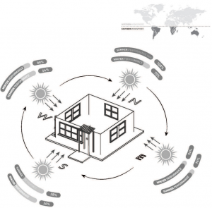
LIGHT TRANSMISSION
Light transmission can vary widely with the number of window panes and types of coatings. The type of glass needs to be assessed. Approximate transmission factors are:
| Glass Type |
Transmission Factors |
| Single Panel |
70% |
| Double Panel |
63% |
| Double Panel with bronze tint |
30% |
| Double Panel with selective low-e coating |
45% – 57% |
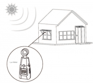
ASSESSING THE INSTALLATION LOCATION
PRE INSTALLATION ASSESSMENT
- Measuring sunlight through the windowHold the Lux meter directly against the window glass indoors in the location you wish to mount the solar panel, and observe the KLux Reading.
- Estimate performanceUsing the time of the day that the measurement was taken, select the coefficient that corresponds to your region / time of year.
Time of Measurement on a Particular Day
Coefficient in January (North Hemisphere) & July (South Hemisphere) Coefficient in July (North Hemisphere) & January (South Hemisphere)
1:00 AM
0 0
2:00 AM
0 0
3:00 AM
0.00 0.00
4:00 AM
0.00 0.00
5:00 AM
0.00 0.00
6:00 AM
0.00 13.64
7:00 AM
0.00 4.96
8:00 AM
0.00 2.97
9:00 AM
5.57 1.95
10:00 AM
1.79 1.53
11:00 AM
1.24 1.34
12:00 PM
1.00 1.09
1:00 PM
1.02 1.00
2:00 PM
1.06 1.07
3:00 PM
1.51 1.16
4:00 PM
2.26 1.32
5:00 PM
0.00 1.69
6:00 PM
0.00 2.56
7:00 PM
0.00 5.34
8:00 PM
0.00 0.00
9:00 PM
0.00 0.00
10:00 PM
0.00 0.00
11:00 PM
0.00 0.00
12:00 PM
0.00 0.00
Note: 0.00 coefficient means that the sunlight intensity is too low to be measured accurately.
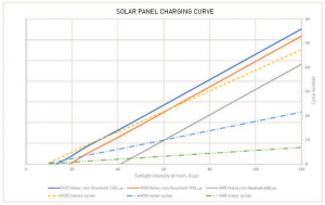
Use the value calculated from the table above with the graph below to estimate the number of cycles that the solar panel can provide over a 24 hour period.
EXAMPLE OF PRE INSTALLATION ASSESSMENT
Measuring sunlight intensity at 3:00 PM during winter of Northern Hemisphere, for a M25 motor installation:
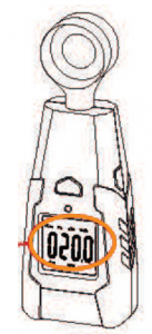
- Measuring sunlight through the windowMeasure the KLux using a Lux meterMeasured Value = 20KLux
- Estimate performanceMultiply the measured Value by the coefficient in the table on page 9.Sunlight intensity = Measured Value x coefficientSunlight intensity = 20KLux x 1.51 = 30.2KLuxCalculated sunlight intensity = 30.2KLuxLocate 30.2KLux on the x-axis and draw a vertical line from it until it meets the motor curve.Draw a horizontal line intersecting the vertical line and the y-axis; gives an estimated number of cycles (within a 24-hour period) that can be achieved without depleting the battery level. i.e. the motor is only consuming energy harvested from the sun.In this case it is approximately 10 cycles.
 Calculated sunlight intensity = 30.2KLuxLocate 30.2KLux on the x-axis and draw a vertical line from it until it meets the motor curve.Draw a horizontal line intersecting the vertical line and the y-axis; gives an estimated number of cycles (within a 24-hour period) that can be achieved without depleting the battery level. i.e. the motor is only consuming energy harvested from the sun.In this case it is approximately 10 cycles.
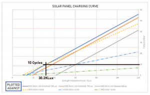
INSTALLATION
MOUNTING OPTIONS
OPTION A. Attaching Mounting Bracket to Window Frame
OPTION B. Attaching Solar Panel via Velcro Strip to a Window or surface
Solar panel should not be too far from the window because the performance will be reduced.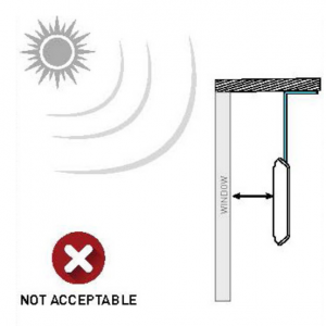
Keep the solar panel as close to the window as possible.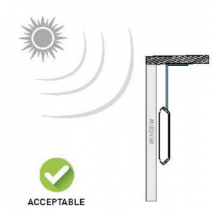
The back of the bracket should not be facing opposite to the window.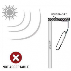
The back of the bracket should be facing toward the window.
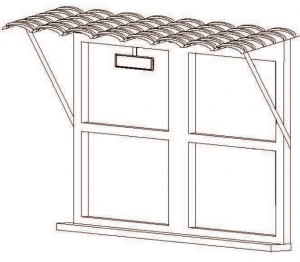
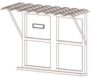
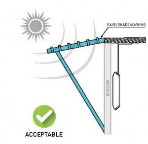
In case of an eave, shade or awning, the bracket should not be bent.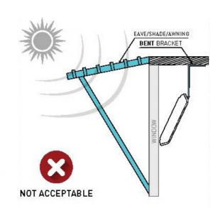
HORIZONTAL ORIENTATION
Use velcro strips to stick the bracket on the window (horizontal orientation).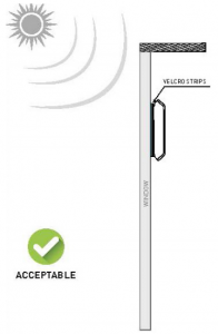
VERTICAL ORIENTATION
Use velcro strips to stick the bracket on the window (vertical orientation).
INSTALLATION PROCESS
![]() IMPORTANTFully charge the Motor or Battery Pack before beginning Solar Panel installation.
IMPORTANTFully charge the Motor or Battery Pack before beginning Solar Panel installation.
Locate the optimal position for solar panel in window.Ensure all components are available for installation scenario.
![]() IMPORTANTEnsure solar panel has adequate exposure to sunlight. When selecting a position for solar panel, consider any external obstructions like trees, building, signs, etc. that may limit the amount of sun light reaching onto the solar panel.
IMPORTANTEnsure solar panel has adequate exposure to sunlight. When selecting a position for solar panel, consider any external obstructions like trees, building, signs, etc. that may limit the amount of sun light reaching onto the solar panel.
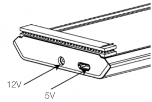
![]() IMPORTANTThe PV panel supports two motor voltages; however a single PV panel can only charge one motor type at a time. That is, if the 12V port is connected to a 12V motor, the USB (5V) port is switched off. Conversely If the 12V port is NOT connected, the USB port is automatically switched on.
IMPORTANTThe PV panel supports two motor voltages; however a single PV panel can only charge one motor type at a time. That is, if the 12V port is connected to a 12V motor, the USB (5V) port is switched off. Conversely If the 12V port is NOT connected, the USB port is automatically switched on.
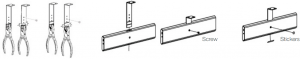
OPTION A. Attaching Mounting Bracket to Window Frame
i. Break off excess bracket length using Pliers (if required).ii. Install mounting bracket to wall/mounting point.iii. Fix Solar panel to mounting bracket using screw.iv. Apply stickers onto the Solar Panel to seal unused mounting holes.
OPTION B. Attaching Solar Panel via Velcro Strip to a Window or surface
- Clean solar panel front surface with alcohol wipe. Allow surface to dry.
- Peel protective film off one side of Dual Lock and attach to one end of solar panel. Press adhesive tape firmly onto solar panel surface for 5 seconds to ensure good adhesion. Ensure that Dual Lock does NOT cover any portion of the solar panel cells. Repeat previous steps for attaching adhesive tape to other end of solar panel.
- Apply stickers onto the solar panel to seal unused mounting holes.
- Clean the window or surface with alcohol wipe. Allow surface to dry. Peel protective film off Dual Locks. Press firmly onto fixing surface. Apply hand pressure for 5 seconds and check if firmly attached.


![]() IMPORTANTAny partial or total covering of any solar panel cell will degrade solar panel performance.
IMPORTANTAny partial or total covering of any solar panel cell will degrade solar panel performance.
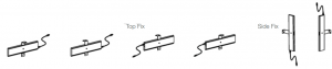
BENDING BRACKET
Bracket can be bent in order to receive more direct sunlight which provides more energy to the motor.
![]() IMPORTANTBend the bracket prior to installation of the solar panel.
IMPORTANTBend the bracket prior to installation of the solar panel.
The bracket should be bent at a distance of 22 mm, 36 mm or 48 mm from the base of the bracket as shown below:

![]() IMPORTANTEnsure the bend angle is between 150° to 180°.
IMPORTANTEnsure the bend angle is between 150° to 180°.
![]() IMPORTANTMake sure that the solar panel has adequate exposure to sunlight.
IMPORTANTMake sure that the solar panel has adequate exposure to sunlight.
CONNECTING SOLAR PANEL WITH MOTOR
Connect solar panel with the motor.

![]() IMPORTANTEnsure any cables are kept clear of fabric at all times.
IMPORTANTEnsure any cables are kept clear of fabric at all times.
12V Compatible Components
| Item # | Description |
| RTMLBC | Rechargeable Battery Pack (optional) |
| RTMLCXT48 | 12V Charger Cable Extender 48″ |
| RTMLCXT96 | 12V Charger Cable Extender 96″ |
5V Compatible Components
| Item # | Description |
| RTMLDSSUSB | USB Charger Cable 13′, 20 AWG |
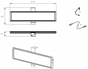
DIMENSIONS
TROUBLESHOOTING
| Problem | Cause | Remedy |
| Motor is not responding | Remote control battery is discharged | Replace battery. |
| Battery is inserted incorrectly into remote control | Check battery polarity. | |
| Radio interference / shielding | Ensure remote is positioned away from metal objects and the antenna on motor is kept straight. | |
| Motor distance is too far from remote control | Move remote to a closer position. | |
| Battery power depleted | Recharge with AC Adaptor (optional). | |
| Incorrect wiring | Check that motor wiring is connected correctly (refer to motor installation instructions). | |
| Motor beeps 10 times when in use | Battery voltage is low / Solar Panel issueSolar Panel not providing enough power | Check connection and positioning of Solar Panel. Ensure sun exposure is adequate.Recharge with AC Adaptor (optional). |
| No output Voltage from Round Connector | Not enough light | Turn the orientation of Solar Panel for more light energy. |
| Round Connector is open circuit | Connect battery motor for 5 minutes to check charge current. | |
| Motor battery capacity is full | Run the motor continuously until the battery voltage is below 12 V. | |
| No output of USB Connector | Round Connector is charging battery motor | Disconnect the motor from the Round Connector. |
Any Questions?Contact our R-TEC Automation® in-house experts at 866.985.3423. Email us at [email protected].

[xyz-ips snippet=”download-snippet”]