
Race Sport Lighting RSUKIT LED UNDERBODY KITINSTALLATION GUIDE
PARTS LIST (INCLUDED IN THE KIT)
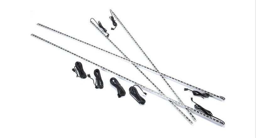
1 x LED Control Center Box2 x 48” RGB Aluminum Channel LED Bars2 x 36” RGB Aluminum Channel LED Bars1 x E-Z 20-Button Pad Remote (batteries included)1 x E-Z Keychain Remote (batteries included)4 x 10’ LED Strip Extension Wire1 x Mounting Hardware Kit
12v Power Options:A- 1 x Car ChargerB- 3 x Direct Fuse taps (3 available sizes)C- Control Box – fuse wiring
GENERAL INSTALLATION GUIDE
The ROKIT Underbody Kit is unique in that installation is fully customizable. Therefore, we have offered a general guideline which includes “DO’S” AND “DON’TS”. Please read carefully through this manual prior to installation.
![]()
Professional installation is highly recommended.(May Require Drilling)
Minute Underbody LED Kit Power Test
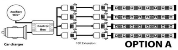
- As shown below in OPTION A. connect all light strips to the control box via the included extension cables.
- Once connected. plug the control box car charger into an available car charger port.
- Turn on your vehicle and click “ON” on the car charger adapter.
- Using the included E-2 Remote, click through each color and pattern.
LED UNDERBODY KIT POWERING: DO’S AND DON’T’S
DO’SSelect option A or B to connect the kit to a 12v power source.
OPTION A: Using the car charger adapter, plug your cigarette adapter into any 12v power source inside your vehicle. Connect to the control box and test for power.
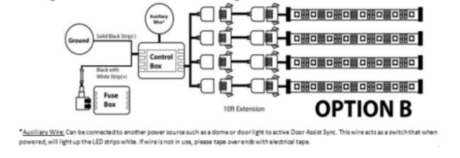
OPTION B: Use the fuse adapters for a cleaner look with the interior without the extra wiring.
- Open the fuse box. Usually found underneath your driver footwell or, in the engine bay.
- Find an open slot or an existing fuse that matches the size of one of the 3 fuse taps (included).
- Connect the control box fuse wiring with the fuse tap by crimping the positive wire (black and white wire) fuse tap.
- Connect the open negative wire to a ground (any metal surface).
- Plug the fuse tap into the open fuse slot. If you also had to remove an existing fuse for the fuse tap, plug the removed fuse into the open slot of the fuse tap.
- Plug the other end of the control box-fuse wiring into the control box.
DON’TsWe do not recommend, nor does our warranty cover a custom installation. We strongly recommend using one of the options listed above.
Mounting the Control Box: DO’s & DON’TsDO’sOur control box also comes with an auxiliary third wire that is switch-activated. You may use it to tap into another source that activates your cars such as a door or dome light.If you are not using the auxiliary third wire, we recommend you cover the end with electrical tape to prevent electrical interference.Do mount your control box in a secure location using double-sided tape/ Velcro tape/ screw mount.
DON’TsDo not place the control box in a location that may get wet. The control box is not waterproof andmay get damaged in water. Water damage is not covered by our warranty.Do not cut or shorten any of the wires on the control box. Doing so will void the warranty.Do not attempt to install the Auxiliary wire/ “Door-Assist” option without a licensed professional installer.Do not place any components of the LED Underbody Kit within 8” of hot (exhaust) or, moving parts.
LED Bar Mounting Locations: DO’s & DON’Ts
DO’sWe do strongly recommend this part of the installation be performed by a licensed professional installer.Do find a safe and open area to install the Underbody Kit. We strongly recommend raising the vehicle on a carmount.Do test the location of your lighting surface prior to mounting/ drilling.Loosely mount the LED light bars using tape (not included). This process should give you a good idea ofhow the Underbody Kit will look when it’s fully mounted.
Turn the key once to the auxiliary setting without starting the car. Ensure the car charger button is set to “ON”. Activate the kit by using the E-Z Remote.Do use the proper size and type of drill bit for the type of surface being drilled.For the 48” bars that apply to the sides of the vehicle, we generally recommend mounting on a pinch weld or, the side skirt molding.Do test mount the extension wiring using tape prior to finalizing with zip ties.Do test the vehicle’s clearance once it’s back on the ground. Turn the steering wheel as far as possible in bothdirections to check for clearance or, any moving parts. Parts damaged due to tire contact or, any other moving parts voids the warranty.
LED Mounting Bracket & Zip Tie Installation & UseBracketsScrew the brackets into the desired location. Insert a zip tie in-between the bracket as shown below. Place the LED bar on the bracket. Wrap the zip tie over the LED bar and pull tight.Use at least 3-4 mounting brackets per LED bar. Try to place them as straight as possible for proper alignment.
Zip TiesIf there are no mounting locations for the brackets, it is recommended that zip ties be used to secure the LED bar.Find metal mounting points that the zip tie can loop around. If none are available, you may need to drill a mounting hole for the zip tie.
DON’TsDo not drill or mount the LED bar onto or, near the radiator.Do not drill multiple holes at the same time without testing/ measuring fitment and alignment. Drill one hole at a time.Always drill the holes for the 2 end brackets first.Do not place any components of the Underbody Kit within 8” of any moving or, hot surface.Be aware of brake lines and fuel lines when running the wires, or, mounting the LED bar.Keep wires away from any moving parts. Use additional zip ties to minimize any wire slack.
Finalizing Installation
Do consider adding a bead of silicone gel (not included) around the edges of the snap-connectors to preventcorrosion of the connector pins. This is especially recommended if your vehicle is exposed to salted roads.Ensure that all wires and LED bars are securely mounted onto the vehicle.Do test for full remote functionality once all connections are in place.
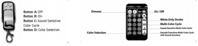
Dual Remote Control Features and Use
Warranty and Disclaimer
Installation of this product must be performed by a licensed professional. Should the failure of the product be the result of damage occurring as a result of improper installation, alteration of the product or, an act or omission on the part of the consumer, Race Sport Lighting shall not be held responsible for any consequential damages which arise from the use and/ or installation of the product. If the LED Kit is installed in any manner other than specified, Race Sport Lighting reserves the right to deny any warranty claims at the discretion of the technical support department. Any product return must include the original packaging, invoice number and, a statement of the alleged defect upon receipt of the product.
Additional Disclaimer Terms
Please refer to local and state laws for the proper use of this product. Improper installation of electrical products such as lighting may cause damage to a vehicle’s electrical system or, connected devices. Practice extreme caution and follow all established safety procedures and common-sense best practices. This product could require the handling of high voltage wiring. Electricity could cause injury or death. Professional installation is strongly recommended. Race Sports Lighting will not be held responsible for any damage or cost whether directly or, indirectly incurred by the consumer in relation to any Race Sport Lighting product.
[xyz-ips snippet=”download-snippet”]