RadioLink T8FB 8-Channel Remote Controller User Manual
- Please be kindly noted that this manual will be updated regularly and please visit RadioLink official website to download the latest version:www.radiolink.com


Thank you for purchasing RadioLink 8-channel remote controller T8FB.
To fully enjoy the benefits of this product and ensure safety, please read the manual carefully and set up the device as instructed steps.If any problems found during the operation process, either way listed below can be used as online technical support.
- Send mails to [email protected] and we will answer your question at the earliest.
- Send message to us on our Facebook page or leave comments on our YouTube page
- If purchased from an approved dealer or distributor, you can contact them directly for support. All manuals and firmwares are available on RadioLink official website www.radiolink.com and more tutorials are uploaded. Or follow our Facebook and YouTube homepage to stay tuned with our latest news.
SAFETY PRECAUTIONS
- Never operate models during adverse weather conditions. Poor visibility can cause disorientation and loss of control of pilots’ model.
- Never use this product in a crowd or illegal areas.
- Always check all servos and their connections prior to each run.
- Always be sure about turning off the receiver before the transmitter.
- To ensure the best radio communication, please enjoy the flight/driving at the space without interference such as high voltage cable, communication base station or launching tower.
WARNING
This product is not a toy and is NOT suitable for children under the age of 14. Adults should keep the product out of the reach of children and exercise caution when operating this product in the presence of children. Never operate your model during adverse weather conditions. Water or moisture may enter the transmitter inside through gaps in the antenna or joystick and cause model instability, even out of control. If running in the wet weather(such as game) is inevitable, always use plastic bags or waterproof cloth to cover the transmitter. This device complies with part 15 of the FCC Rules. Operation is subject to the following two conditions:
This device may not cause harmful interference, and prevents external wireless interference, including interference that may cause undesired operation.
Any Changes or modifications not expressly approved by the party responsible for compliance could void the user’s authority to operate the equipment.
Introduction
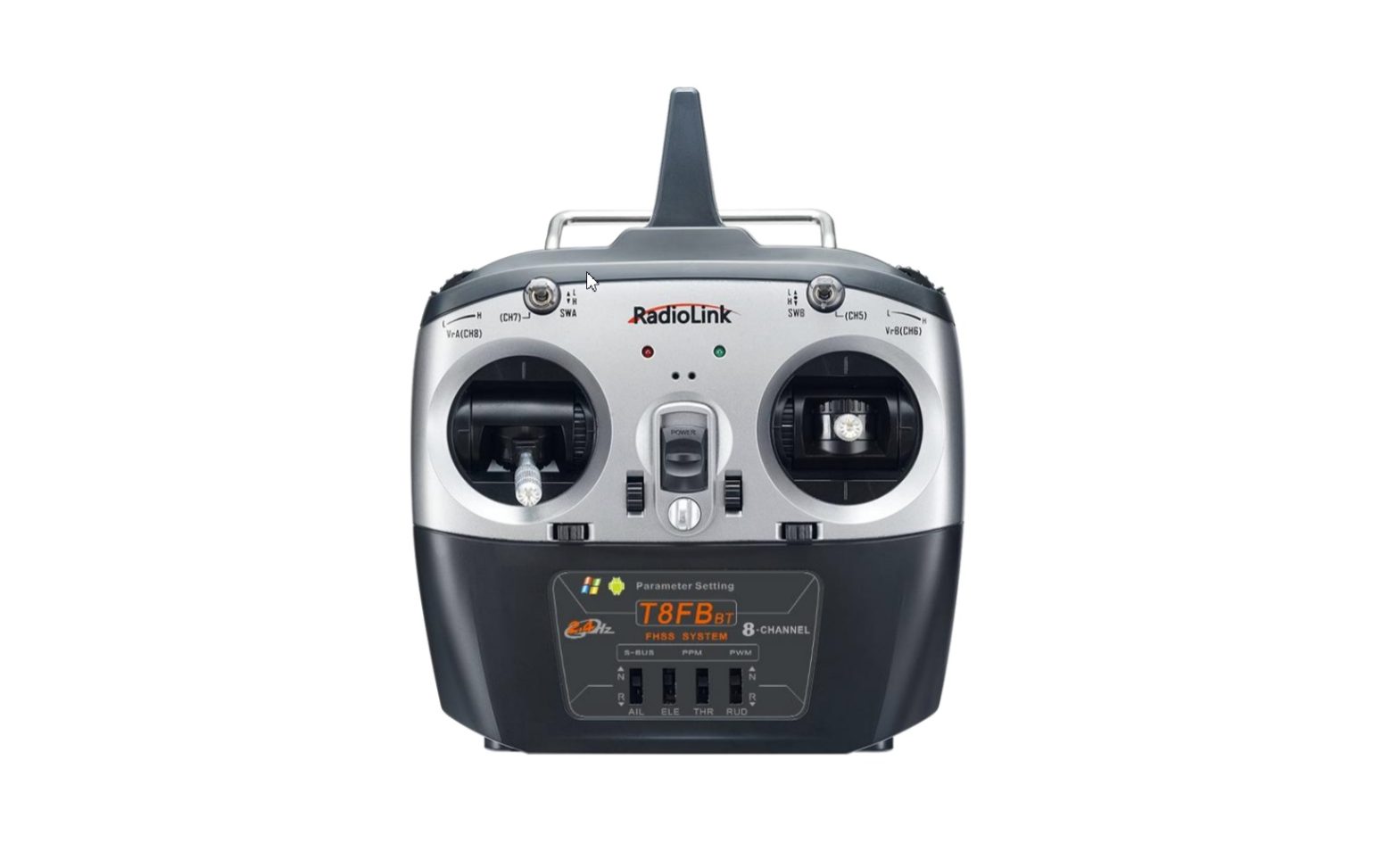
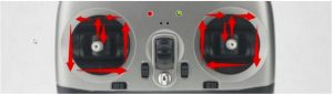
As image of T8FB (Mode 2) shown below, there are one two way switch, one three-way switch, two VR switches, four trimmer buttons and two joysticks. The Mode can be personalized to 1(throttle on right hand) or 2 (throttle on left hand) or both sticks return to center points with the small accessory packed in the bag.
Factory setting by default: SwB is CH5, VrB is CH6 , SwA is CH7 and VrA is CH8.
Universal JST battery connector supports multiple batteries, including 4pcs AA batteries or 2S/3S/4S LiPo battery. Default low battery alarm voltage will be automatically set according to the battery used. Or pilots can personalize the alarm value with the mobile APP or computer software.

Note The phases of the 4 channels can be easily changed by prodding the corresponding phase switches instead of modifying the parameter data in the software/APP.
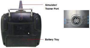
- Earth Pole
- Null
- Voltage Input: 7.4-15V
- Output: PPM
- Input:RSS
T8FB Basic Setup
Receivers
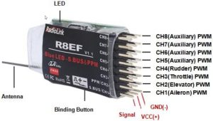
The standard receiver packed with T8FB is R8EF, 8-channel receiver with PWM and SBUS/PPM signal output supported.
Signal Working Mode
- PWM Working Mode:Receiver indicator is RED with all 8 channels output PWM signal.
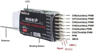
- SBUS/PPM Working ModeReceiver indicator is Blue(Purple) with 8 channels output in total. Channel 1 is SBUS signal, channel 2 PPM signal and channel 3 to 8 PWM signal.
Signal Switch between SBUS&PPM and PWM
Short press the binding button on the receiver twice within 1 second to switch the SBUS/PPM signal to PWM signal.
Binding
Every transmitter owns a unique ID code. Before using, binding transmitter to receiver on aircraft is a must. When done binding, ID code will be stored in the receiver, no need to rebind, unless the receiver is going to work with another transmitter. If a new compatible receiver is purchased, binding needs to be done before using.
Binding steps of all transmitters and receivers from RadioLink are the same as follow:
- Put the transmitter and the receiver close to each other (about 50 centimeters) and power both on.
- Switch on the transmitter and the LED on R8EF will start flashing slowly.
- There is a black binding button(ID SET) on the side of receiver. Press the button until the LED flashing quickly and release, meaning binding process is ongoing.
- When the LED stops flashing and is always on, binding is complete. If not succeed, the LED will keep flashing slowly to notify, repeat the above steps.
Note of Receiver Usage
- Keep antennas as straight as possible, or the effective control range will reduce.
- Big models may contain metal parts that influence signal emission. In this case, antennas should be positioned at both sides of the model to ensure the best signal status in all circumstances.
- Antennas should be kept away from metal conductor and carbon fiber at least half inch away and no over bending.
- Keep antennas away from motor, ESC or other possible interference sources.
- Sponge or foam material is advised to use to prevent vibration when installing receiver.
- Receiver contains some electronic components of high-precision. Be careful to avoid strong vibration and high temperature.
- Special vibration-proof material for R/C like foam or rubber cloth is used to pack to protect receiver. Keeping the receiver in a well-sealed plastic bag can avoid humidity and dust, which would possibly make the receiver out of control.
T8FB Calibration
Press rudder trimmer left and turn on transmitter at the same time. When the transmitter is power-off, toggle both sticks at the central point. Then press the rudder trimmer button left and the power button simultaneously, red and green LED will start flashing and the T8FB is ready to be calibrated..
Range Calibration: Toggle both sticks (Ch1-4) to the highest point/maximum and the lowest point/minimum. Then back to the central point. (Refer to image below)
Central Point Calibration: When the joysticks are back to the central point, press rudder trimmer right, and then red and green LED always on means sticks calibration is done with success. Then turn off T8FB and repower it on.
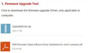
Firmware Upgrade
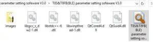
T8FB can be update with latest functions added, keeping advanced as always.The function of data backup makes massive copy possible, even the same model can directly copy data. Set parameters once, copy at ease! The whole file with all necessary tools can be downloaded fromhttps://www.radiolink.com/t8fb_bt_firmwares
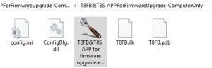
- Driver Installation: Follow the steps in the PDF file and install the driver.
- Connect T8FB to computer via an android USB cable of data transmission (NOT charging function only).
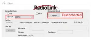
- Open the software to upgrade T8FB firmware and choose the correct COM port.
- Click CONNECT and press the power button once quickly within 1 second. When “DISCONNECT” in RED turns to “CONNECT” in GREEN, it means it’s connected with success.
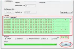
- Click APROM and choose the latest firmware downloaded from https://www.radiolink.com/t8fb_bt_firmwares
- The factory default firmware of T8FB is the latest. And firmware will be regularly updated and available on RadioLink website.
- Click “START” and the process bar becomes GREEN. When the green bar goes to the end and shows PASS, the firmware is upgraded with success.
Parameters Setup via Mobile APP
APP Installation
Android APP: Visit https://www.radiolink.com/t8fb_bt_app to download the android app to setup T8FB parameters by Bluetooth connection.
Apple APP: Search radiolink in Apple store and download.
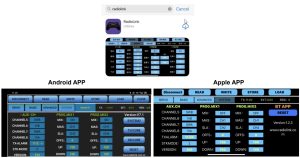
Different from the current Apple App, the current Android APP has two more programmable mixing controls, Throttle Curve and DR Curve parameter setup menus and customizable RSSI/Model Voltage Alarm.
- Latest APPs with new functions added will be updated regularly, please always take the version on https://www.radiolink.com/T8FB_apps as the latest.
APP Connection
Connection of both Android APP and Apple APP to T8FB are the same as below:
- When the installation of parameter setup APP is complete, press the power button to turn on T8FB.
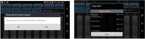
- Click to enter the APP, a message will pop out to ask for permission to turn on the Bluetooth function.
- Click CONNECT on the top left of the parameter setup interface, a list of devices will pop out for selection.
- Select RadioLink device, the two LED indicators at rightmost will flash with DD sounds.
- Press any of the trimmer buttons to stop the DD sounds and the servo range will display on the APP, meaning connection between the APP and T8FB succeed.
- If fail, please repeat the above steps to try again.
Parameters setup of both Android APP and Apple APP are the same as below: There are 6 function keys on the top of the parameter setup interface.
(DIS)CONNECT: When APP is opened on the mobile and T8FB is powered on, click CONNECT and a list of Bluetooth devices will pop out and select the RadioLink device to make connection. The two leds at the rightmost will flash in turn with DD sounds, press any of the trimmer buttons to stop the DD sounds and the servo range will display on the APP. If fails, press DISCONNECT and CONNECT again.READ: Click READ, two short D sounds will be heard and the APP starts reading the data in T8FB. The current data of the T8FB won’t display on the APP until clicking READ.WRITE: Click to update the changed data into the T8FB and two slow D sounds mean the modified data have been written in T8FB. If no D sound means update failure, please reconnect T8FB to the App and re-write. Click WRITE each time parameter is modified to make sure it’s well input to the T8FB.STORE: Click to save the APP data as a file in the mobile.LOAD: Click LOAD and a pop out of ‘Model Select’ will display and user can either create a new file or select among the saved files.CLOSE: Click CLOSE to exit.
There are 4 more parameters displaying next to SYSTEM : Model data selected/T8FB voltage(TX)/RSSI/ Model voltage(EXT, works only with RadioLink receivers of telemetry function R7FG or R8F).
Parameters Setting Steps and Multiple Model Data Storage
- When parameters need to be modified, click READ first to input the original data from T8FB into the APP, then modify as wish and click WRITE to output the modified data to T8FB.
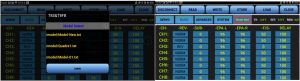
- Click LOAD and a pop out of ‘Model Select’ will display, click NEW to create a new file /model/Model-New.txt. Click it to select and tab the file name next to the SYSTEM to rename. Setup all the data then click STORE to save under the personalized name.
- When parameters STORE as TXT file need to be input, click LOAD first to select from the saved data files into the APP then click WRITE to copy them to T8FB.
Note If the new file created is forgotten to rename but STORE as Model-New, the data in this file will be cleaned automatically when trying to create another new file sharing the same file name.
There are 7 parameter setup menus:
|
No |
Menu |
|
1 |
SERVO |
| 2 |
BASIC |
|
3 |
ADVANCED |
| 4 |
SYSTEM |
|
5 |
SYSTEM2 |
| 6 |
TH/CURE |
|
7 |
DR/CURE |
| 8 |
RESET |
The above menus are all available on Android APP V7.1 and above. Menu No 1. to 4 are available on Apple APP. The latest APP will be frequently updated on RadioLink official website www.radiolink.com . 3.3.1 SERVO Menu.
SERVO Menu
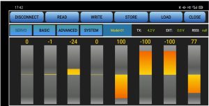
The 8 rectangles show the CH1-CH8 servos range (4 basic channels and 4 auxiliary channels) from left to right. CH1–Aileron, CH2 – Elevator, CH3 – Throttle,CH4–Rudder, CH5 to CH8–Auxiliary channels.
BASIC Menu
There are 6 parameters to setup including” REV” “SUB” “EPA-L” “EPA-R” “F/S” “DELAY”
REV: Defines the relationship between the transmitter controls and the receiver output for channels with options of NORM and REV. Make sure to check all servos move to the correct direction as wish under control. Make sure to check all servos move to the correct direction under control.
NoteIf programmable mix control function is used to control several servos for fixed wing/gliders, eg. V-TAIL mix control, make sure to set the phase to avoid possible confusion.
SUB: Makes small changes or corrections to the neutral position of each servo. The default is 0 setting by factory setting. That is, no SUB-TRIM. The range is from -100 to +100 and can be modified with actual need.It’s advised to center the digital trims before making SUB-TRIM changes, and keep all of the SUB-TRIM values as small as possible. In order to restrict the servo travel range, the recommended procedure is as follows:
- Measure and record the desired surface position;
- Zero out the SUB-TRIM;
- Mount servo arms and linkages so that the control surface’s neutral is as correct as possible;
- Modify with SUB-TRIM small range value to make fine corrections.
EPA-L &EPA-R: Sets the range of each channel in percentage. The most flexible version of travel adjustment is available. It independently adjusts each end of each individual servo’s travel, rather than one setting for the servo affecting both directions. The default value is 96 with the range from 0 to 120.
F/S: (Fail-safe) sets responsive action of model in case of signal loss or low T8FB voltage. Each channel can be set independently. The F/S (Fail Safe) function moves each servo to a predetermined position.
NoteThe setting of the throttle F/S also applies to the low battery voltage. F/S value 0 means throttle stick at the lowest point while 50 means at the central point. The F/S (Fail-safe) function is used in certain competitions to ensure safety landing of the model prior to flying away and dropping. Conversely, it can also be used make all servos neutral to maximize the flight time.
DELAY: Adjusts the synchronous ratio between the servos position and the actual operation. The default value is 100 by factory setting meaning no delay.
ADVANCED Menu
There are four parameters to setup:” D/R” “ATTITUDE” “ELEVON” “V-TAIL”
D/R: Sets the auxiliary switch to control the max and min values of corresponding channel range. Turn on “MIX” (mix control) first and choose an auxiliary switch to flip and set the max/min range value to its corresponding channel by toggling. In the example picture shown above: When flip SWA upward and toggle CH1 stick, it means the max/min range of CH1 can be +100 and -100. If the UP value modified to 50, it means the max range can only be +50/-50 when toggle CH1 up and down. ‘DOWN” means when flip SWA downward, the max/min value of CH1 is +100/-100.
ATTITUDE: Select the preferred channel from CH5 through CH8. CH5 is always the default switch to change attitude when connect to flight controller PIXHAWK/MINI PIX/APM/TURBO PIX while CH7 is default when connect to DJI flight controller. For the default channel to switch attitudes, please refer to the flight controller user manual.The values behind each channel means different control percentage output different control signals. The default values of T8FB of each attitude is corresponding to the values of flight controller PIXHAWK/MINI PIX/APM/TURBO PIX. That is, when the above flight controllers are used with T8FB, attitude can be selected on the Mission Planner and no need to setup specific parameter.
ELEVON: Turn on “MIX” (mix control) first, adjust the aileron distance and allow aileron differential.ADJUSTABILITY:
- CH1 and CH2 are required.
- Independently adjustable aileron travel allows aileron differential.
- Independently adjustable elevator travel allows for differences in up & down travel.
- The separate ELEVON settings for each condition can be set. (GLIDER only)
V-TAIL: This function is used on the V-tail aircraft. V-TAIL mixing is used with v tail aircraft so that both elevator and rudder functions are combined for the two tail surfaces. Both elevator and rudder travel can be adjusted independently on each surface.
ADJUSTABILITY:
- CH2 and CH4 are required.
- independently adjustable travel allows for differences in servo travels.
- Rudder differential is not available. To create rudder differential, set RUDD1 and RUDD2 as 0, then use two programmable mixes in SYSTEM Menu, RUD-ELE and RUD-RUD, setting different percentages for up and down. These are new rudder travels. Turn the trim and link off, switch assignment null so rudder won’t be accidentally turned off.
Note
V-TAIL function and ELEVON/AILEVATOR mix functions can’t be activated at the same time. Make sure to move the elevator and rudder sticks regularly while checking the servo motions. If a large travel value is set, when the sticks are moved at the same time, the controls may mutually disturb or run out of travel. Decrease the travel until no disturbance occurs. 3.3.4
SYSTEM MenuThere are totally two system menus in Android APP with the quantity of programmable mixing controls is increased to four.
AUX-CHCH5/6/7/8 can be personalized to different switches. If any of the auxiliary channels is not for use, NULL should be set.TX-ALARMThe default low voltage value is automatically set according to the battery used(2S 7.3V/3S-11.0V) and also can be personalized as well. When the transmitter voltage is lower than the value set, T8FB will make D sound to warn.STK-MODE(SYSTEM)It’s always the default mode of the T8FB with data READ by the APP.Mode 1: left joystick-Rudder and Elevator; right joystick-Aileron and ThrottleMode 2: left joystick-Rudder and Throttle, right joystick-Aileron and ElevatorMode 3: left joystick-Aileron and Elevator, right joystick-Rudder and ThrottleMode 4: left joystick- Aileron and Throttle, right joystick-Rudder and ElevatorVERSION (Under STK-MODE,SYSTEM)The numbers mean current firmware versions which can be upgraded. The detailed steps of firmware upgrade.Note The other version on the right (above SYSTEM2) is the APP version.EXT-ALARM(SYSTEM2)To return the model voltage, RadioLink receivers of telemetry functions R7FG or R8F should be used. The low voltage alarm value can be personalized. When the model voltage goes lower than the set value, T8FB will make D sound to warn. * This function is currently available on Android APP V7.1 and above.RSSI-ALARM(SYSTEM2)The RSSI alarm value can be personalized. When the RSSI goes lower than the set value, T8FB will make D sound to warn.
- This function is currently available on Android APP V7.1 and above.
PROG.MIX
Programmable mixing controls are to
- Diversify attitude changes of aircraft (e.g. Rolling to realize when rudder is commanded);
- Control a certain axis with two or more servos (e.g. 2 rudder servos);
- Correct special movement automatically (e.g. Lower FLAP and ELEVATOR servos at the same time);
- Control the second channel to respond to the movement of the first channel (e.g. Increase smoke oil to respond to high speed, but only when the smoke switch is activated).;
- Turn off the main control under certain circumstances (e.g. For dual-engine aircraft, turn off a motor or speed up/down one motor to assist rudder to turn)
Adjustability: Channel 1 to 8 can be personalized to mix.MAS: Master channel. Other channels need to cooperate with movements of the master channels.SLA: Slave channel. Many mix controls are controlled by one master channel.E.g. Rudder Aileron mix control with Master as rudder while Slave as aileron and OFFS as 0 and UP as 25% to correct rolling. No switch is needed.
THROTTLE CUT Setup
This function is achievable with T8FB programmable mix controls setting.In SYSTEM Menu, turn on the Mix Control, set Master as CH1 while Slave as CH8 with the OFFS value as -100. Then in ADVANCED Menu, turn on the D/R MIX function, set CH as CH3 and the DOWN value as 0. Then toggle the CH8 Toggle-Switch to the right most and the setting is complete.
- There are totally 4 mixing controls on Android APP V7.1 and above while 2 mixing controls on Apple APP.
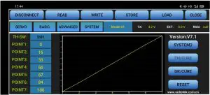
TH/CURE
Throttle curve is the set output travel by throttle. It is to coordinate the motor response and the throttle operation. The horizontal ordinate is the joystick position while the vertical ordinate is the throttle output. * This menu is currently available on Android APP V7.1 and above.
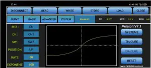
DR/CURE
Dual rate curve is the function to switch from different servo travels to achieve different controls. For example, aeroplane requires different maximum servo travels for different flight status, pilots can use this function to switch from different servo angles.
- This menu is currently available on Android APP V7.1 and above.
RESET
This function is to restore the factory setting when necessary. When press this button, T8FB will make three slow D sounds, meaning default setting is set.
T8FB Parameters Setup via Computer
Software Installation and Connection
- Connect the computer to the T8FB with an android USB data cable
- Open the parameter setup software in the downloaded file,then power on T8FB
- Choose Port Number( COM port will be automatically identified when connected), setting baud rate: 115200, 8-1-None(8 data bits, 1 stop bit, no parity check), click OPEN to connect. These parameters are on the right of the software interface.
- T8FB will continuously make D sounds, press any of the trimmer buttons to stop the DD sounds.Note: When click OPEN to connect, the SETTING parts mentioned above will turn grey and can’t be changed and PARAMETERS of the connected T8FB includes TX-ALARM/STK MODE/VERSION, at bottom right will be displayed.

READ: T8FB data will be read and displayed on computer when click “READ”. The two LEDs at the rightmost will flash once at the same time with two D sounds .LOAD: The data file in TXT format saved will be loaded in the software. Click “browse” to select the preferred data file and load it into the software.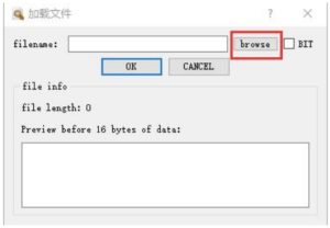 UPDATE: Modify the data as wish or load the data which is saved as file then click “UPDATE” to input the new parameter into T8FB. (two green LEDs at the rightmost will flash slightly with two D sounds. Click at least four times to make sure the modified data is well input or repower on the T8FB to double confirm if the data is well input).SAVE: The data read or set will be saved as TXT file in the computer. This is very helpful if there are several sets of radio data need to be saved or if one set of parameters need to be copied in different radios.
Parameters Setting Steps
- When parameters need to be modified, click READ first to input the original data into the software, then modify as wish and click UPDATE to output the modified data to T8FB.
- When parameters SAVE as TXT file need to be input, click LOAD first to input the saved data into the software then click UPDATE to copy them to T8FB.
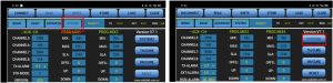
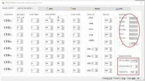
BASIC Menu
There are 6 parameters to setup: “REVERSE”” SUB-TRIM”” END POINT”” FAIL SAFE”” AUX-CH”” DELAY”
REVERSE: Defines the relationship between the transmitter controls and the receiver output for channels with option of NORM and REV. Refer to 3.3.2-REV (P7) for more details.
SUB-TRIM:Makes small changes or corrections to the neutral position of each servo. Refer to 3.3.2-SUB (P8) for more details.
END POINT:Sets the range of each channel (in percentage);The most flexible version of travel adjustment is available. It independently adjusts each end of each individual servo’s travel, rather than one setting for the servo affecting both directions. Refer to 3.3.2-EPA-L &EPA-R (P8) for more details.
FAIL SAFE:Sets responsive action of model in case of signal loss or low Rx voltage (in percentage). Refer to 3.3.2-F/S (P8) for more details.
AUX-CH:Defines the relationship between the transmitter controls and the receiver output for channels 5-8. Refer to 3.3.4(P10) for more details.
DELAY:Adjust the ratio between the position of servos and the actual operation. Refer to 3.3.2-DELAY (P8) for more details.
TX-ALARM:The default low voltage value is automatically set according to the battery used(2S-7.3V/3S-11.0V) and also can be personalized as well. When the transmitter voltage is lower than the value set, T8FB will make D sound to warn.
STK-MODEIt’s always the default mode of the T8FB with data READ by the APP.Mode 1: left joystick-Rudder and Elevator; right joystick-Aileron and ThrottleMode 2: left joystick-Rudder and Throttle, right joystick-Aileron and ElevatorMode 3: left joystick-Aileron and Elevator, right joystick-Rudder and ThrottleMode 4: left joystick- Aileron and Throttle, right joystick-Rudder and Elevator
VERSIONThe numbers mean different firmware versions which can be upgraded. The detailed steps of firmware upgrade.
ADVANCED Menu
There are six parameters setup ”D/R” “ATTITUDE” “ELEVON” “V TAIL”PROG.MIX1/PROG.MIX2 as below shown,please refer to 3.3.3 (P10-11) and 3.3.4(P11-12) for more details..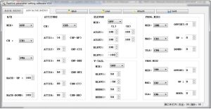
T8FB Specification
- Size: 173*102*206mm
- Weight: 0.47kg
- Operating Voltage: 4.8~18V
- Operating Current: <80mA
- Output Frequency: 2.4GHz ISM band (2400MHz~2483.5MHz)
- Modulation Mode: GFSK
- Spread Spectrum: FHSS 67 channels pseudo-random frequency hopping
- Control Range: 2000 meter (Maximum range tested in unobstructed areas free of interference and may vary depending on local regulations)
- Transmitter Power: <100mW(20dBM)
- Section Precision: 4096, 0.5us/section
- Compatible receivers: R8EF(Standard),R8SM, R8FM, R8F,R7FG, R6FG, R6F, R4FGM,R4F
R8EF Specification
- Size: 41.5*21.5*11.5mm
- Weight: 14g
- Channel: 8CH
- Signal Output: SBUS&PPM&PWM
- Operating Current: 30mA
- Operating Voltage: 4.8-10V
- Control Range: 2km in the air (Maximum range tested in unobstructed areas free of interference and may vary depending on local regulations)
- Compatible transmitters: T8FB/T8S/ RC6GS V2/RC4GS V2
 report this ad
Thank you again for choosing RadioLink product.
References
[xyz-ips snippet=”download-snippet”]