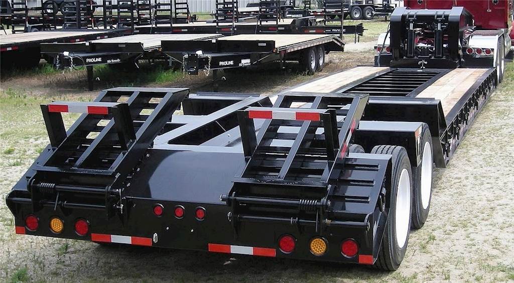

DETACHABLE GOOSENECK USERS MANUAL
WARNING:This User’s Manual contains safety information and instructions for your trailer. You must read this manual before loading or towing your trailer. You must follow all safety precautions and instructions.
SAFETY INFORMATION
SAFETY ALERT SYMBOLS AND SIGNAL WORDS
Loss of control of the trailer or trailer/tow vehicle combination can result in death or serious injury. The most common causes for loss of control of the trailer are:
- Driving too fast for the conditions (maximum speed when towing a trailer is 60 m.p.h.);
- Overloading the trailer or loading the trailer unevenly;
- Trailer improperly coupled to the hitch;
- Inadequate tow vehicle or towing hitch;
- No braking on trailer;
- Not maintaining proper tire pressure;
- Not keeping lug nuts tight; and
- Not properly maintaining the trailer structure.
An owner’s manual that provides general trailer information cannot cover all of the specific details necessary for the proper combination of every trailer, tow vehicle and hitch. Therefore, you must read, understand and follow the instructions given by the tow vehicle and trailer hitch manufacturers, as well as the instructions in this manual. The safety information in this manual is denoted by the safety alert symbol: ^ The level of risk is indicated by the following signal words.
WARNING:WARNING – Hazards or unsafe practices which COULD result in severe personal injury or death if the warning is ignored.
Notice:NOTICE – Practices that could result in damage to the trailer or other property.
MAJOR HAZARDS
Driving Too Fast
With ideal road conditions, the maximum speed when safely towing a trailer is 60 M.P.H. If you drive too fast, the trailer tires will overheat and possibly blowout. As your speed increases, you are more likely to suddenly lose control. Never exceed 60 M.P.H. while towing the trailer.
WARNING:Driving too fast for conditions can result in loss of control and cause death or serious injury.Decrease your speed as road, weather and lighting conditions deteriorate.
Failure to Adjust Handling While Towing a Trailer
When towing a trailer, you will have decreased acceleration, increased stopping distance, and increased turning radius (which means you must make wider turns to keep from hitting curbs, vehicles, and anything else that is on the inside corner). You will also need longer distances in which to pass due to slower acceleration and increased length.
- Be alert for slippery conditions. You are more likely to be affected by slippery road surfaces when driving a tow vehicle with a trailer, than driving a tow vehicle without a trailer.
- Anticipate the trailer “swaying.” Swaying is the trailer reaction to the air pressure wave caused by passing trucks and busses. Continued pulling of the trailer provides a stabilizing force to correct swaying. Do not apply the brakes to correct trailer swaying.
- Check rearview mirrors frequently to observe the trailer and traffic.
- Use lower gear when driving down steep or long grades. Use the engine and transmission as a brake. Do not ride the brakes, as they can overheat and become ineffective.
- Be aware of your load height, especially when approaching bridges
Trailer Not Properly Coupled to the Fifth Wheel
t is critical that the trailer be securely coupled to the fifth wheel, and that the jaws of the fifth wheel plate are properly closed around the kingpin. Uncoupling may result in death or serious injury.
WARNING:An improperly coupled trailer can result in death or serious injury. See section 2.2.1.1 for coupling instructions.
Unsafe Tires, Lug Nuts or Wheels
Trailer tires and wheels are more likely to fail than car tires and wheels because they carry a heavier load. Therefore, it is essential to inspect the trailer tires before each tow.
If a tire has a bald spot, bulge, cuts, is showing any cords, or is cracked, replace the tire before towing. If a tire has uneven tread wear, take the trailer to a dealer service center for diagnosis. Uneven tread wear can be caused by tire imbalance, axle misalignment or incorrect inflation.
Tires with too little tread will not provide adequate tracking on wet roadways and can result in loss of control, leading to death or serious injury.
Improper tire pressure causes an unstable trailer and can result in a tire blowout and loss of control. Therefore, before each tow you must also check the tire pressure. Tire pressure must be checked when tires are cold. Allow 3 hours for cool-down after driving as much as 1 mile at 40 M.P.H. before checking tire pressure. NOTE: Trailer tires will be inflated to higher pressures than passenger vehicle tires.
WARNING:Improper tire pressure can result in a blowout and loss of control, which can lead to death or serious injury.Ensure that tires are inflated to the pressure indicated on side wall before towing trailer.
Since trailer wheels and lug nuts are subjected to greater side loads than automobile wheels, they are more prone to loosen. Before each tow, check to make sure they are tight.
WARNING:Metal creep between the wheel rim and lug nuts will cause rim to loosen and could result in a wheel coming off, leading to death or serious injury.Tighten lug nuts before each tow.
Lug nuts shall be tightened to a minimum of 450 ft-lbs. and a maximum of 550 ft-lbs. Use a torque wrench to tighten the lug nuts. If you do not have a torque wrench, use a lug wrench (from your tow vehicle) and tighten the nuts as much as you can. Then have a service garage or trailer dealer tighten the lug nuts to the proper torque.
Lug nuts are also prone to loosen after first being assembled. When driving a new trailer (or after wheels have been remounted), check to make sure they are tight after the first 100 and 500 miles of driving and before each tow thereafter.
Failure to perform this check can result in a wheel parting from the trailer and a crash, leading to death or serious injury.
Overload
The total weight of the load you put on your trailer, plus the empty weight of the trailer itself, must not exceed the trailer’s Gross Vehicle Weight Rating (GVWR). If you do not know the empty weight of the trailer, you must measure it at a commercial scale. In addition, you must distribute the load on the trailer such that the load on any tire or axle does not exceed the tire load rating or the Gross Axle Weight Rating (GAWR).
WARNING:An overloaded trailer can result in loss of control of the trailer, leading to death or serious injury.Do not load a trailer so that the weight on any tire exceeds its rating.Do not exceed the trailer Gross Vehicle Weight Rating (GVWR) or an axle Gross Axle Weight Rating (GAWR).
Unsafe Load Distribution
Uneven load distribution can cause tire, wheel, axle or structural failure. Be sure your trailer is properly loaded.
A proper weight distribution is equal, right to left; and creates a kingpin weight that is in the proper range for stable trailer handling.
The rule of thumb percentage of total weight of the trailer plus its cargo (Gross Vehicle Weight, or “GVW”) that should appear on the kingpin of the trailer for a fifth wheel coupling is 20 to 25%. For example a trailer with a loaded weight of 80,000 pounds, should have 20-25% of 80,000 pounds on the tongue. That is, the example trailer would have 16,000 to 20,000 pounds on its kingpin.
WARNING:Improper kingpin weight (load distribution) can result in loss of control of the trailer, leading to death or serious injury.Ensure that the kingpin weight is within the allowable range.
Towing stability also depends on keeping the center of gravity as low as possible. Load heavy items on the floor, and over the axles, but do not exceed the axle load rating (GAWR). When loading additional items, be sure to maintain even side-to-side weight distribution and proper kingpin weight.
Shifting Cargo
Since the trailer “ride” can be bumpy and rough, you must secure your cargo so that it does not shift while the trailer is being towed.
WARNING:Shifting cargo can result in loss of control of the trailer, and can lead to death or serious injury.Tie down all loads with properly sized chains, fasteners, straps, etc.
Inoperable Lights
Ensure that all of the lights on your trailer are functioning properly before towing your trailer.
- Check the trailer tail lights by turning on your tow vehicle headlights.
- Check the trailer brake lights by having someone step on the tow vehicle brake pedal while you look at trailer lights.
- Do the same thing to check the turn signal lights.
WARNING:Improper electrical connection between the tractor and the trailer will result in inoperable lights, and can lead to collision. Before each tow:Ensure that the taillights, brake lights and turn signals work
Inoperable Brakes
Ensure that all of the brakes on your trailer are functioning properly before towing your trailer.
- Test Low Pressure Warning Signal. Shut the engine off when you have enough air pressure so that the low pressure warning signal is not on. Turn the electrical power on and step on and off the brake pedal to reduce air tank pressure. The low air pressure warning signal must come on before the pressure drops to less than 60 psi in the air tank. If the warning signal doesn’t work, you could lose air pressure and you would not know it. This could cause sudden emergency braking.
- Ensure that Spring Brakes Come On Automatically. Continue to fan off the air pressure by stepping on and off the brake pedal to reduce tank pressure. The tractor protection valve and parking brake valve should close (pop out) when the air pressure falls to the manufacturer’s specification (20 – 40 psi). This will cause the spring brakes to come on.
- Test Air Leakage Rate. With a fully-charged air system (typically 125 psi), turn off the engine, release the parking brake, and time the air pressure drop. The loss rate should be less than three psi in one minute for combination vehicles. Then apply 90 psi or more with the brake pedal. After the initial pressure drop, if the air pressure falls more than four psi for combination vehicles, the air loss rate is too much. Check for air leaks and fix before driving the vehicle. Otherwise, you could lose your brakes while driving.
- Check Air Compressor Governor Cut-in and Cut-out Pressures. Pumping by the air compressor should start at about 100 psi and stop at about 125 psi. Run the engine at a fast idle. The air governor should cut-out the air compressor at about the 125 psi. The air pressure shown by your gauge(s) will stop rising. With the engine idling, step on and off the brake to reduce the air tank pressure. The compressor should cut-in at about 100 psi. The pressure should begin to rise. (Cut-in and Cut-out pressures can vary per manufacturer.) If the air governor does not work as described above, it may need to be fixed. A governor that does not work properly may not keep enough air pressure for safe driving.
- Test Parking Brake. Stop the vehicle, put the parking brake on, and gently pull against it in a low gear to test that the parking brake will hold.
- Test Service Brakes. Wait for normal air pressure, release the parking brake, move the vehicle forward slowly (about five mph), and apply the brakes firmly using the brake pedal. Note any vehicle “pulling” to one side, unusual feel, or delayed stopping action. This test may show you problems, which you otherwise wouldn’t know about until you needed the brakes on the road.
Hazards From Modifying Your Trailer
- Essential safety items can be damaged by altering your trailer. Even simply driving a nail or screw to hang something can damage an electrical circuit, air line or other feature of the trailer. Alteration of the trailer structure or modification of mechanical, electrical, wiring or other systems on your trailer will void your warranty unless performed by Rampant Trailers LLC.
COUPLING TO THE TOW VEHICLE
USE AN ADEQUATE TOW VEHICLE AND HITCH
If the vehicle is not properly selected and matched to the Gross Vehicle Weight Rating (GVWR) of your trailer, you can cause an accident that could lead to death or serious injury. If you already have a tow vehicle, know your vehicle tow rating and ensure that the trailer’s rated capacity is less than or equal to the tow vehicle’s rated towing capacity.
Warning:Use of a tow vehicle with a towing capacity less than the load rating of the trailer can result in loss of control, and may lead to death or serious injury.Be sure your tow vehicle is rated for the Gross Vehicle Weight Rating of your trailer.
COUPLING AND UNCOUPLING THE TRAILER
A secure coupling (or fastening) of the trailer to the tow vehicle is essential. A loss of coupling may result in death or serious injury. Therefore, you must understand and follow all of the instructions for coupling.
Fifth-wheel Coupler
A fifth wheel coupling provides the link between a semi-trailer and the towing truck. The coupling consists of a coupling pin (or king pin) on the front of the semi-trailer, and a horseshoe-shaped coupling device called a fifth wheel on the rear of the tractor.
Coupling the Trailer with the Fifth Wheel
- Ensure that the size and rating of the fifth wheel and kingpin match.
- Wipe the kingpin clean and inspect it visually and by feel for flat spots, cracks and pits. Check the condition of the fifth wheel plate on the tractor.
WARNING:A worn, bent, cracked or corroded kingpin can fail while towing, and may result in death or serious injury.Before coupling the trailer, inspect the kingpin and fifth wheel plate for wear, bending, cracks or corrosion; and replace worn or damaged kingpin.
- Ensure that the fifth wheel mechanism operates freely.
- Lubricate the fifth wheel plate surface with a light coat of Lithium-base, waterproof grease.
- Ensure that the fifth wheel and kingpin fasteners are tight and all welds are solid.
WARNING:A loose fifth wheel or kingpin can result in uncoupling, leading to death or serious injury.Be sure the fifth wheel and kingpin are tight before coupling the trailer.
- Ensure that the air lines, electrical line, and hydraulic lines (if applicable) are clear of the coupling area.
- Ensure that the locks are open.
- Ensure that the gooseneck is lifted high enough such that the coupler plate and the kingpin on the trailer will not hit any part of the truck or truck frame until it reaches the fifth wheel plate. (See Figure 2.2.1.1a)
* Note: The coupler plate on the trailer should hit about mid-way up the sloped fifth wheel plate and slide the remaining distance. If the neck is not high enough, it can be lifted using the hydraulic control lever labeled “lift cylinder”.
Notice:Engagement of the PTO on the truck’s hydraulic system prior to connecting the hydraulic lines to the trailer could cause serious damage to the hydraulic system.
Notice:DO NOT lift the neck too high as this could cause severe damage to the hinged compression block assembly.
WARNING:If the trailer neck drops during coupling, death or serious injury may result.There must be no one under the neck of the trailer or coupler before or during the coupling operation.
 Figure 2.2.1.1a
- Back the tractor up close to the trailer, centering the kingpin in the slot of the fifth wheel. Continue backing up until the fifth wheel locks firmly on the kingpin.
- Visually check to confirm that the fifth wheel locks are properly locked onto the kingpin.
Raise the trailer using the hydraulic neck
- If not already done, engage the appropriate hydraulic system by either connecting the hydraulic lines from the tractor and engaging the PTO or by starting the engine to the self contained hydraulic kit.
Notice:Engagement of the PTO on the truck’s hydraulic system prior to connecting the hydraulic lines to the trailer could cause serious damage to the hydraulic system
- Connect the air lines and electric lines to the trailer.
- Ensure that the “ride lock pin” between the detachable neck and the trailer is in the “locked” position and there is no part of the pin protruding above the pin sleeve. (See Figure 2.2.1.2a)
- If the “ride lock pin” is not fully engaged, lift the trailer off the ground using the hydraulic control lever labelled “lift cylinder”. Then lower the trailer to the ground again using the same hydraulic control lever. This should re-align the trailer and allow the “ride lock pin” to slide freely into place.
- If the “ride lock pin” still does not fully engage, it may be necessary to detach the gooseneck and re-align. (See Section 3.1 Detachable Neck Operation)
WARNING:If “ride lock pin” is not fully engaged as shown in Figure 2.2.1.2a, the gooseneck can become uncoupled from the chassis during transport resulting in serious injury or death.
 Figure 2.2.1.2a
- Using the hydraulic control lever labeled “lift cylinder”, lift the trailer until the hinged compression blocks are free to swing and can be moved into one of the three “ride positions.” (See Figure 2.2.1.2b)
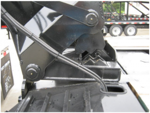 Figure 2.2.1.2b
- Using the hydraulic control lever labeled “lift cylinder”, lower the trailer into one of the three desired ride positions until the hinged compression blocks are fully engaged and a tight connection is achieved. (See Figure 2.2.1.2c)
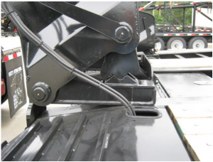 Figure 2.2.1.2c
NoticeDo not “over-compress” the hinged compression blocks as this could put unnecessary strain on the neck base
- Connect the air lines and electrical cable which run from the trailer to the gooseneck.
- Perform safety check for lighting outlined in Section 1.2.8.
- Perform safety check for braking system outlined in Section 1.2.9.
Uncoupling the Fifth-Wheel from the Trailer
- Ensure that the ground surface below the trailer bearing area will support the trailer tongue load.
- Ensure that the “neck lock pin” is properly installed. (See Figure 2.2.1.3a)
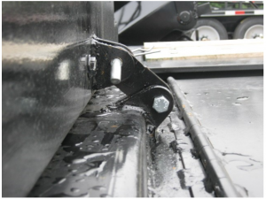 Figure 2.2.1.3a
- Shut off the air supply to the trailer which will lock the trailer brakes and ensure that the “ride lock pin” between the detachable neck and the trailer is in the “locked” position. (See Figure 2.2.1.2a)
- Engage the appropriate hydraulic system by either engaging the PTO on the tractor or starting the engine to the self contained hydraulic kit.
- Using the hydraulic control lever labeled “lift cylinder”, lift the trailer until the hinged compression blocks are free to swing. (See Figure 2.2.1.2b)
- Rotate the hinged compression block arm towards the tractor to its “storage catch” therefore freeing the chassis to be lowered to the ground without damaging the cylinder support tube. (See Figure 2.2.1.3b)
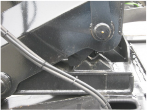 Figure 2.2.1.3b
WARNING:Failure to stand clear of trailer bearing area when lowering trailer to the ground can result in serious injury or death.
- Continue to raise the front of the detachable neck and shift the weight of the neck from the tractor to the trailer by pushing the hydraulic control lever labeled “lift cylinder” in the down direction. Do not lift the neck too high as this could cause severe damage to the hinged compression block assembly.
- Lift neck only high enough such that the kingpin plate is slightly above the fifth wheel plate. (See Figure 2.2.1.2a)
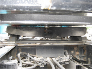 Figure 2.2.1.2a
Notice:DO NOT lift the neck too high as this could cause severe damage to the hinged compression block assembly.
- Open the fifth wheel lock by pulling the release handle.
- Disengage the hydraulic system and disconnect the hydraulic lines from the tractor (if applicable), or turn off the engine to the self contained hydraulic kit.
- Disconnect the air lines and electric line.
- Slowly pull the tractor forward
LOADING THE TRAILER
To safely load a trailer, the following factors must be considered:
- Weight of the load
- Distribution of the load
- Securing of the load
The total weight of the load must not be more than the rated capacity of the trailer.
There are two areas of concern when trying to properly distribute the load on the trailer.
The load distribution must be such that no individual component of the trailer is loaded beyond its rating. If loaded to capacity, the load must be in a span of 12’ or greater.
Towing stability also depends on keeping the center of gravity as low as possible. Load heavy items on the floor and over the axles. When loading additional items, be sure to maintain even side-to-side weight distribution and proper tongue weight. The total weight of the trailer and its contents must never exceed the total weight rating of the trailer (Gross Vehicle Weight Rating, or “GVWR”).
WARNING:An overloaded trailer can result in loss of control of the trailer, leading to death or serious injury.Do not exceed the trailer Gross Vehicle Weight Rating (GVWR) or an axle Gross Axle Weight Rating (GAWR).
DETACHABLE NECK OPERATION
Detaching the Neck from the Trailer
- Ensure that the ground surface below the trailer bearing area will support the trailer tongue load.
WARNING:Failure to stand clear of trailer bearing area when lowering trailer to the ground can result in serious injury or death.
- Ensure that the “neck lock pin” is disengaged therefore allowing the neck to disconnect from the deck.
- Ensure that the air supply to the trailer is on therefore giving full control to the “ride lock pin” between the detachable neck and the trailer.
- Disengage or lift the “ride lock pin” by pulling the knob labeled “ride lock pin control”. Failure to fully disengage the “ride lock pin” can result in severe damage to the trailer as well as personal injury or death. (See Figure 3.1.1a)
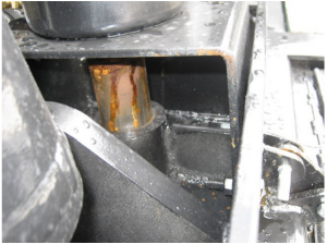 Figure 3.1.1a
WARNING:Failure to fully disengage the “ride lock pin” can result in severe damage to the trailer, serious injury, or death.
- Disconnect the air lines and electrical cable which run from the trailer to the gooseneck. Store the air hoses and electrical cable in the designated storage area.
- Engage the appropriate hydraulic system by either engaging the PTO on the tractor or starting the engine to the self contained hydraulic kit.
- Using the hydraulic control lever labeled “lift cylinder”, lift the trailer until the hinged compression blocks are free to swing. (See Figure 2.2.1.2b)
- Rotate the hinged compression block arm towards the tractor to its “storage catch” therefore freeing the chassis to be lowered to the ground without damaging the cylinder support tube. (See Figure 2.2.1.3b)
- Continue lowering the trailer until the (2) – trailer support pins are disengaged and approximately centered in the carrying plates on the base of the neck. (See Figure 3.1.1b)
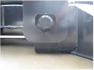 Figure 3.1.1b
- Using the hydraulic control lever labeled “truck cylinder”, lower the truck support arm down onto the truck frame and force the truck frame down until the neck just starts to lift. Adjust the height so that the neck is slightly lifted off of the trailer deck. (See Figure 3.1.1c)
- DO NOT CONTINUE TO LOWER THE TRUCK SUPPORT ARM AFTER THE NECK COMES SLIGHTLY OFF THE TRAILER DECK. THIS COULD CAUSE SEVERE DAMAGE TO THE TRUCK REST ASSEMBLY.
Notice:Do not continue to lower the truck support arm after the neck comes slightly off the trailer deck. This could cause severe damage to the truck rest assembly.
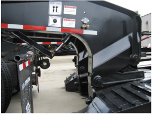 Figure 3.1.1c
- Slowly pull the tow vehicle away from the trailer.
- If on uneven ground it may be necessary to lift the neck higher off the ground using the hydraulic control lever labeled “truck cylinder” before moving the tow vehicle freely.
- The trailer is now ready to be loaded. DO NOT SIDE LOAD.
Notice:Side loading can result in severe damage to the trailer.
Attaching the Neck to the Trailer
- Ensure that the air supply to the trailer is on therefore giving full control to the “ride lock pin” between the detachable neck and the trailer.
- Disengage or lift the “ride lock pin” by pulling the knob labeled “ride lock pin control”. Failure to fully disengage the “ride lock pin” can result in severe damage to the trailer. (See Figure 3.1.2a)
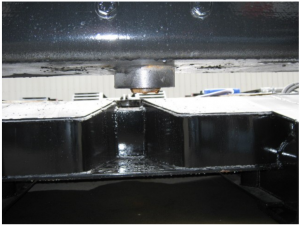 Figure 3.1.2a
- Ensure that the neck is lifted high enough such that the neck base is higher than the neck bearing area. (See Figure 3.1.2b)
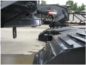 Figure 3.1.2b
- Center the neck with the trailer and slowly back up until the neck base is in a position such that it will have about 4 to 6 inches of bearing on the neck bearing area when lowered. Do not back the towing vehicle and the neck to the point that the neck is fully engaged to the trailer. (See Figure 3.1.2c)
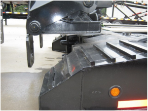 Figure 3.1.2c
- Lower the neck using the hydraulic control lever labeled “truck cylinder” until all the weight of the neck is bearing on the neck bearing area and the “truck cylinder” is fully retracted. (See Figure 3.1.2d)
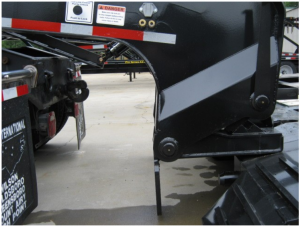 Figure 3.1.2d
- Ensure that the “ride lock pin” sleeve is within the “V” shaped trough and the “ride lock pin” is disengaged or in the up position. (See Figure 3.1.2e)
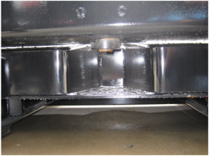 Figure 3.1.2e
Notice:Failure to fully disengage the “ride lock pin” can result in severe damage to the trailer.
- Back the towing vehicle and the neck up until the neck is fully engaged to the trailer. (See Figure 3.1.2f)
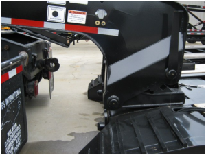 Figure 3.1.2f
- Engage or lower the “ride lock pin” by pushing the knob labeled “ride lock pin control”. (See Figure 2.2.1.2a)
- Ensure that the “ride lock pin” between the detachable neck and the trailer is in the “locked” position and there is no part of the pin protruding above the pin sleeve. (See Figure 2.2.1.2a)
- Lift the trailer using the hydraulic control lever labeled “lift cylinder”.
- If the “ride lock pin” does not engage or lower immediately, lower the trailer to the ground again by using the hydraulic control labeled “lift cylinder”. This should re-align the trailer and allow the “ride lock pin” to slide freely into place.
- If the “ride lock pin” still does not fully engage, it may be necessary to detach the gooseneck and re-align.
WARNING:If “ride lock pin” is not fully engaged as shown in Figure 2.2.1.2a, the gooseneck can become uncoupled from the chassis during transport resulting in serious injury or death.
WARNING:Failure to stand clear of trailer bearing area when lowering trailer to the ground can result in serious injury or death.
- After the “ride lock pin” is fully engaged or lowered, lift the trailer using the hydraulic control labeled “lift cylinder” until the hinged compression blocks are free to swing and can be moved into one of the three “ride positions.” (See Figure 2.2.1.2b)
- Using the hydraulic control lever labeled “lift cylinder”, lower the trailer into one of the three desired ride positions until the hinged compression blocks are fully engaged and a tight connection is achieved. (See Figure 2.2.1.2c)
Notice:Do not “over-compress” the hingedcompression blocks as this could put unnecessary strain on the neck base.
- Connect the air lines and electrical cable which run from the trailer to the gooseneck.
- Perform safety check for lighting outlined in Section 1.2.8.
- Perform safety check for braking system outlined in section 1.2.9.
BREAKING-IN A NEW TRAILER
RETIGHTEN LUG NUTS AT FIRST 100 & 500 MILES
Wheel lugs can shift and settle quickly after being first assembled, and must be checked after the first 100 and 500 miles of driving. Failure to perform this check may result in a wheel coming loose from the trailer, causing a crash leading to death or serious injury.
WARNING:Lug nuts are prone to loosen after initial installation, which can lead to death or serious injury.Check lug nuts for tightness on a new trailer or when wheel(s) have been remounted after the first 100 and 500 miles of driving.
ADJUST BRAKE SHOES AT FIRST 200 MILES
Brake shoes and drums experience a rapid initial wear. The brakes must be adjusted after the first 200 miles of use, and each 3,000 miles thereafter. Some axles are fitted with a mechanism that will automatically adjust the brake shoes when the trailer is “hard braked” from a forward direction.
Rampant Detachable Gooseneck User Manual – Rampant Detachable Gooseneck User Manual –
[xyz-ips snippet=”download-snippet”]