RCI-X910 Meter Amateur Mobile TransceiverWith Built-in Frequency Counter &Touch Select MulticolorUser’s Manual
Capture 1 Specifications
| GENERAL | |
| Model | RCI-X9 |
| Frequency Range | 28.315-29.660MHz |
| Emission | USB, LSB, AM |
| Frequency Control | Phase-Lock-Loop Synthesizer |
| Frequency Tolerance | 0.005% |
| Frequency Stability | 0.001% |
| Operating Temperature Range | -20°C to +50°C |
| Antenna Impedance | 50 ohm |
| Microphone | Plug-In dynamic; with push-to-talk switch and coiled cord |
| Meter Function | RF Output, RX Receive Signal Strength, SWR, AM Modulation |
| Input Voltage | 13.8 V DC |
| Dimensions | 7 3/8″(W) x 8 3/4″ (D) x 2 1/4″ (H) |
| Weight | 5 lb. 8 oz. |
| TRANSMITTER | |
| RF Power Output | AM: 30W RMSAM/SSB: 120W PEAK POWER |
| RF Transmit Modes | USB, LSB, AM, |
| Antenna Connector | UHF Type, 50 a |
| Modulation | A3E, J3E, |
| Spurious Emissions | > -50 dB |
| Carrier Suppression | -50 dB |
| RECEIVER | |
| Sensitivity | AM : 0.5 JL V for 10dB SinadSSB : 0.25 ii V for 12dB Sinad |
| Image Rejection Ratio | > 50 dB |
| Audio Power Output | 2.5W |
Specifications are subject to change without notice.
Chapter 2 Introduction
congratulations on your purchase of an RCI-X9 10-meter band amateur radio. r RCI-X9 is designed to provide trouble-free service and state-of-the-art communications, incorporating many useful features and functions in the 10:er dual-band radio. Please read this manual thoroughly to ensure proper ‘romance.
| IMPORTANTTo operate this radio, you must possess an amateur radio operator’s license issued by the FCC. Operation of this unit without proper licensing is ILLEGAL and can result in severe penalties. |
| NOTEThe manufacturer is not responsible for any radio or TV interference caused by unauthorized modifications to this equipment. Such modifications could void the user’s authority to operate this equipment |
packing
The following items are included with our RCI-X9. Carefully remove and examine materials from the packing carton. If any items are missing or appear caged, please contact your dealer immediately. Each unit should include:RCI-X9 TransceiverDynamic Microphone (SRA-198 NOISE CANCELLING MIC) Power CordMounting Bracket & HardwareInstallation HardwareOwners Manualrecommended that you save the packing materials for future storage or piping.
Chapter 3 Installation
The RCI-X9 is easy to install. All necessary parts (less the antenna and coax cable) have been included to facilitate installation.
Transceiver Mounting
Choose a suitable location for the transceiver that will allow easy access to the front panel as well as proper air circulation to the back of the unit. If you are installing the unit in a vehicle, attach the mounting bracket first, and then attach the transceiver to the mounting bracket using the hardware provided. Before making any electrical connection, ensure that the transceiver is turned off and the vehicle’s battery is disconnected.
Power Connection
The transceiver operates off of any 12 to 13.8 VDC source. Beware of voltage drops caused by operating from Cigarette Lighter Plugs or long DC wire runs. Sometimes it is best to connect directly to the battery for best RF output and D( audio quality
| NOTEThe condition of a vehicle’s electrical system can affect the operation of your RCI-X9. A low battery, worn generator/ alternator, or poor voltage regulator will impair the performance of the unit as well as the vehicle. |
| CAUTIONVoltageVoltage above 15 VDC will damage the unit. Be sure to check the source voltage before connecting the power cord. |
Chapter 4 Operation
Font Panel

- MICROPHONE: Used to connect the microphone.
- WELCH: This knob is used to eliminate background noise being heard through the receiver, it can be disturbing when no transmissions are being heard through the receiver. To use this re, turn the knob fully counterclockwise and then turn clockwise slowly until the background is just eliminated. Further clockwise rotation will increase the threshold level that a signal overcomes in order to be heard. Only strong signals will be heard at a maximum clockwise LG.
- ON/OFF VOLUME: This knob controls the volume and power of the radio. To turn the radio on, the knob clockwise. Turning the knob further will increase the volume of the receiver.
- F GAIN: Adjust this knob for the desired level of the incoming signal.
- C GAIN: Adjusts the microphone gain in transmit and PA modes. This controls the gain to the t that full talk power is available several inches away from the microphone. In the Public .iss (PA) mode, the control functions as the volume control.
- HO/TIME CONTROL: The ECHO control is used for the echo effect. The TIME is used to control the intervals of the echo sound.
- DIM: This knob controls the level of brightness for the meter lamp, frequency display, channel display and all the indicator LEDs except the SWR warning light.
- TALKBACK/OFF CONTROL: Adjust this knob for the desired volume of Talkback. This is used to monitor your own voice. For example, you could use this feature to compare different microphones.
- PWR: This control allows the user to adjust RF power output.
- FINE CONTROL: Allows variation of the receive frequency above and below the selected receive frequency as shown on the display. This control is intended primarily to tune in SSB signals when communicating with several stations that may not be exactly on frequency. It may also be used to optimize AM/FM signals as described in the operating procedure paragraph. The clarifier can adjust the receive frequency ±1.0KHz but does not affect the transmit frequency or the frequency display.
- CHANNEL SELECTOR: This control is used to select the desired transmit and receive channel.
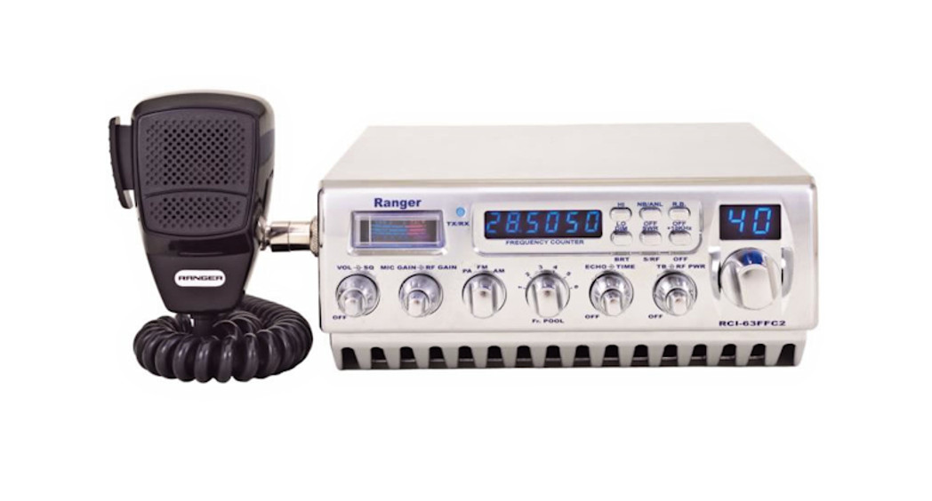
- FRONT PANEL METER: The front panel meter allows the user to monitor incoming signal strength, RF output power, AM modulation, and SWR level.
- SWR/MOD/POWER: This switch controls the function of the meter during the transmit ln the “SWR” position, the meter indicates the Standing Wave Ratio(SWR) of the antenna (accurate at maximum power output). There are no adjustments because the SWR circuit in this radio calibrates itself automatically. When the switch is in the “MOD” position in the AM mode only. lt is accurate- when testing at maximum power output. When this switch is “PWR” position, the meter indicates your power output.
- BAND SELECTOR: This switch is used to select the band.
- BAND SWITCH: The band switch allows the user to select the HI or LO band.
- NB/ANL/RADIO/PA: When the switch is in NB/ANL position, the RF Noise Blanker and Automatic Noise Limiter circuit are active. The noise blanker is very effective for repetitive impulse noise such as ignition interference. ln the PA position, the radio acts as a public address amplifier. Your voice will come out of the speaker that is plugged into the PA. SP. Jack on the rear In the RADIO position, the PA function is disabled and the radio will transmit and receive on the speaker that is connected to the unit.

Remove the retaining screwUnscrew the housing from the pin receptacle bodyLoosen the two cable clamp retainer screws.Feed the microphone cable through the housing, knurled ring, and washer as shown in Fig. 2. wires must now be soldered to the pins as indicated in the above wiring tables. If a vise or mapping tool is available it should be used to hold the pin receptacle body during the soldering .ration, so that both hands are free to perform the soldering. If a vise or clamping tool is not available, the pin receptacle body can be held in a stationary position by inserting it into the; phone jack of the front panel. The numbers of the pins of the microphone plug are shown in . 3, as viewed from the back of the plug. Before soldering the wire to the pins, pre-tin the wire receptacle of each pin of the plug.
Fig. 3 Microphone plug pin numbers viewed from rear of pin receptacle.
Be sure that the housing and the knurled ring of Fig. 2 are pushed back onto the microphone cable before starting to solder. If the washer is not captive to the pin receptacle body, make sure that it is placed on the threaded portion of the pin receptacle body before soldering.If the microphone jack is used to hold the pin receptacle during the soldering operation, the best results are obtained when the connections to pins 1 and 3 are made first and then the connections to pins 2 and 4. Use a minimum amount of solder and be careful to prevent excessive solder accumulation on pins, which could cause a short between the pin and the microphone plug housing.
- When all soldering connections to the pins of the microphone plug are complete, push the knurled ring and the housing forward and screw the housing onto the threaded portion of the pin receptacle body. Note the location of the screw clearance hole in the plug housing with respect to the threaded hole in the pin receptacle body. When the housing is completely threaded into the pin receptacle body, a final fraction of a tum either clockwise or counterclockwise may be required to align the screw hole with the threaded hole in the pin receptacle body. When these are aligned, the retaining screw is then screwed into the place to secure the housing to the pin receptacle body.
- The two cable clamp retainer screws should now be tightened to secure the housing to the microphone cord. If the cutting directions have been carefully followed, the cable clamp should secure to the insulating jacket of the microphone cable.
- Upon completion of the microphone plug wiring, connect and secure the microphone plugin the transceiver.
report this ad867 Bowsprit RoadChula Vista, CA 91914Email:salesPrarmerusa.com http://www.rangerusa.com
PRINTED IN MALAYSIAA382007X9A
[xyz-ips snippet=”download-snippet”]